edenox EXPONORM 651 Quick start guide

Italiano
English
Deutsch
Español
INSTALLAZIONE E USO
INSTALLATION AND USE
ZUSAMMENBAU
UND BETRIEB
INSTALACIÓN Y USO
MANUTENZIONE
MAINTENANCE
INSTANDHALTUNG
MANTENIMIENTO
I
UK
D
E
EXPONORM 651

I
UK
D
E
2
Fig.1 Fig.2
Fig.3
2
3
4
5
3
Fig.4
2
5
5
A
1
Fig.5 Fig.6 55
2
1
2

I
UK
D
E
3
Fig.8
2
3
4
Fig.9
2
Fig.7
2
1
3
5
4
7
6R290
7. Sbrinamento manuale
7. Manual defrosting
7. Manuelles Abtauen
7. Descongelaciòn manual
7. dégivrage manuel
NON rimuovere
il lubrificante
per il primo mese
di vita.
DO NOT remove
the lubricant
for the first month
of life.
das Schmiermittel
NICHT entfernen
für den ersten Monat
des Lebens.
If the supply cord is damaged, it must be replaced
by the manufacturer, its service agent,
or similarly qualified persons in order to avoid a
hazard.
Se il cavo di alimentazione è danneggiato,
deve essere sostituito dal produttore, dal suo
centro di assistenza o da personale qualificato
per evitare rischi
Wenn die Anschlussleitung beschädigt ist, darf sie
nur von einem autorisierten Kundendienst
ausgewechselt werden, um Gefahr zu vermeiden.
Si le câble d'alimentation est endommagé, il doit
être remplacé par le fabricant, des représentants
ou des professionnels agréés afin d'éviter
les dangers.
Si el cable de alimentación está dañado,
debe ser reemplazado por el fabricante, por su
Centro de servicio o personal calificado.
para evitar riesgos

!
!
I
UK
D
E
F
NL
P
S
DK
FIN
B
GR
CZ
EE
LV
LT
H
M
PL
SK
SLO
4
manuale dell’operatore
AVVERTENZE
E' molto importante che questo libretto istruzioni venga conservato con l'apparecchiatura per
consultazioni future, per ragioni di sicurezza.
1. Quest'apparecchiatura deve essere fatta funzionare solo da persone adulte. Non permettere ai
bambini di manomettere i comandi o giocare con essa. . E’ vietato alterare o comunque modificare le2
caratteristiche dell’apparecchiatura. . I lavori elettrici necessari per l'installazione dell'apparecchiatura3
devono essere eseguiti da elettricista qualificato o da persona competente. . Non cercare mai di riparare4
l’apparecchiatura da soli. Riparazioni effettuate da persone inesperte possono causare danni o gravi
disfunzioni. . L'assistenza a questa apparecchiatura deve essere effettuata da un Centro Assistenza5
Tecnico autorizzato. Usare solo ricambi originali. . L'apparecchiatura non è idonea alla conservazione di6
derrate diverse da quelle alimentari. . La casa costruttrice declina ogni responsabilità qualora queste7
norme antinfortunistiche non siano rispettate. La stessa si riserva il diritto di apportare tutte le modifiche
migliorative senza alcun preavviso. . Evitare di installare l’apparecchiatura direttamente ai raggi solari.8
9 10. Non installare l’apparecchiatura vicino a fonti di calore come stufe,caloriferi ecc. . Mantenere le
griglie di ventilazione del gruppo compressore lontano da pareti di almeno 30cm. . Ricordare di non far11
sporgere i prodotti esposti oltre al perimetro dei ripiani o griglie. Qualora si verificasse la formazione12.
anormale di ghiaccio sull’evaporatore,causato dall’umidità dell’aria o dai prodotti da refrigerare,
consigliamo di fermare il compressore mettendo la merce in apposito contenitore refrigerato alla stessa
temperatura per il tempo necessario allo sbrinamento; caso contrario il compressore funzionerà
continuamente provocando un inutile consumo di energia elettrica e uno scarso rendimento. . In caso13
di pause prolungate e spegnimento del frigorifero è INDISPENSABILE lasciare la porta della macchina
semi aperta (per l’intero periodo), necessario ad impedire un ristagno di umidità all’interno della cella.
Evitando ciò, eviterete anche la conseguente formazione di muffa ed odori sgradevoli.
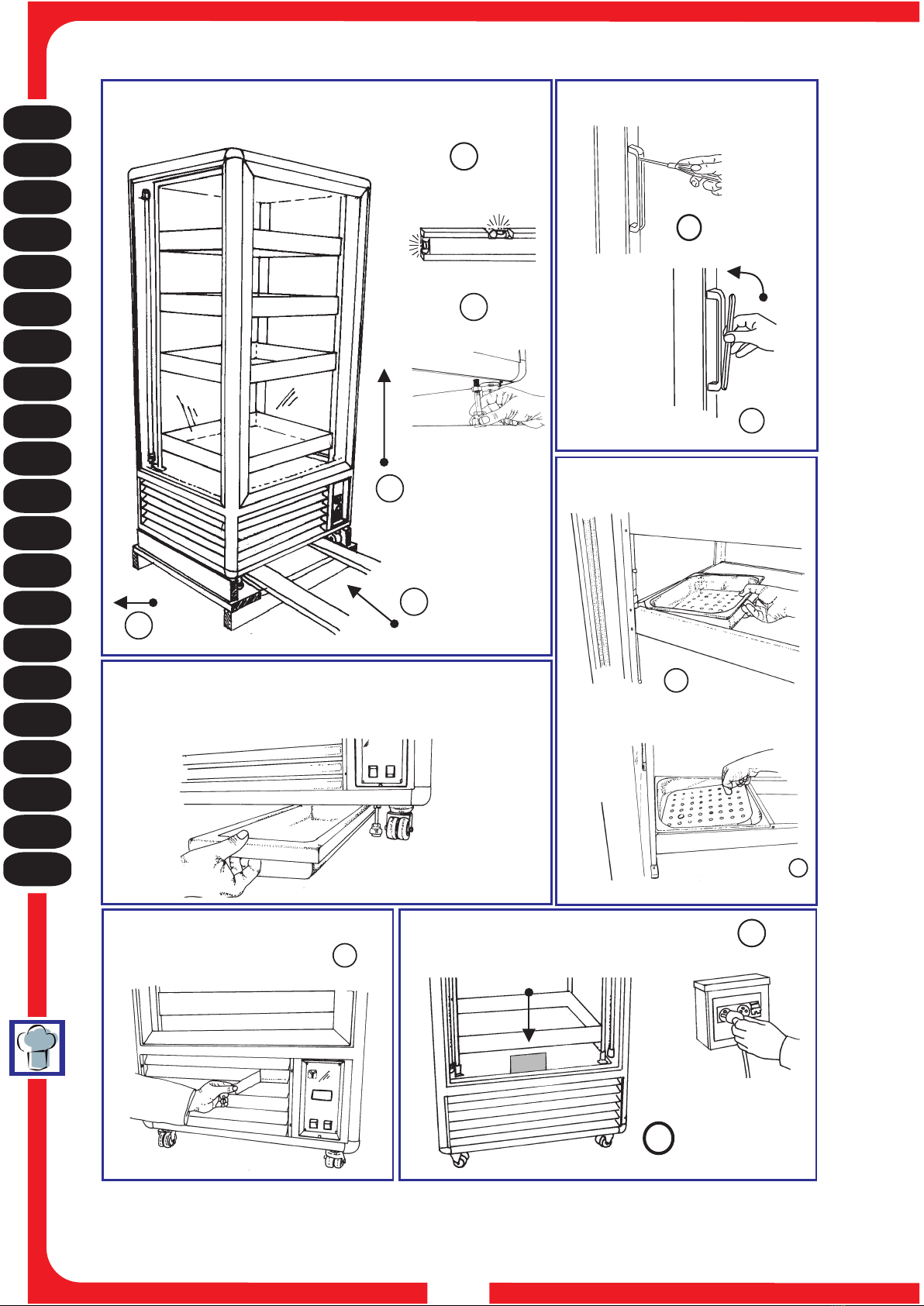
1. APERTURA DELL'IMBALLAGGIO
IMBALLAGGIO IN SCATOLA DI CARTONE 1a. Tagliare la reggia, sfilare la scatola verso l'alto.
IMBALLAGGIO IN CASSA DI LEGNO 1b. Schiodare le tavole di legno, prestando attenzione ai chiodi.
2 3. Infilare le forche del sollevatore fra l’apparecchiatura e pallet o cassa. . Sollevare l’apparecchiatura.
4 5 6. Eliminare il pallet o cassa. . Avvitare i piedini regolabili vicino agli angoli anteriori. . Posare
l’apparecchiatura su un piano livellato orizzontale, registrando l’apposito piedino. . Fare attenzione a7
non lasciare niente nell’imballo prima di buttarlo. . Separare i materiali dell’imballaggio secondo la8
composizione in modo da facilitarne lo smaltimento (vedi Fig.1).
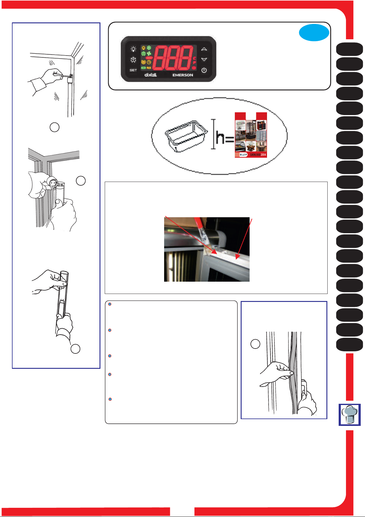
2. LA MANIGLIA
1 2. La maniglia è in una busta all'interno dell’apparecchiatura. . Montare la base della maniglia con le due
viti che si trovano già nei fori sul montante della porta; serrare a fondo. . Applicare l’inserto in plastica,3
premendo fino allo scatto (Vedi fig.2).
3. LA VASCHETTA PER IL PESCE
L'apparecchio a richiesta è dotato di vaschette per il contenimento del pesce, fra queste una ha lo spigolo
smussato da porre in corrispondenza dell'angolo dell’apparecchiatura in cui passa il tubo dell'impianto
refrigerazione. Le vaschette sono fornite con un piano di fondo forato per il drenaggio dell'acqua,
facilmente rimovibile per una facile pulizia (vedi Fig.3).
4. LE VASCHETTE DI RACCOLTA DELL'ACQUA
Prendere la vaschetta in plastica all'interno del mobile e infilarla nelle apposite guide sotto il mobile (vedi
Fig.4).
Manuale dell’operatore:
1. Apertura dell'imballaggio
2. La maniglia
3. La vaschetta per il pesce
4. Le vaschette di raccolta dell'acqua
5. Pulizia dell'interno
6. Pulizia dell'esterno
7. Collegamento alla rete elettrica
8. Regolazione
9. Controllo di un regolare funzionamento
10. Sostituzione lampade interne
11. Sostituzione della guarnizione magnetica della porta
Manuale del manutentore (Pag.48):
1. Pulizia del condensatore
2. Pulizia interna
3. Sostituzione di una vetrata
4. Schema impianto di refrigerazione e schema elettrico
I nostri prodotti sono da interni - non installare all'esterno dei locali/negozi.

I
UK
D
E
F
NL
P
S
DK
FIN
B
GR
CZ
EE
LV
LT
H
M
PL
SK
SLO
5
manuale dell’operatore
5. PULIZIA DELL'INTERNO
1. 2Asportare la pellicola di protezione dall'alluminio di supporto delle vaschette. . Pulire le parti interne e
le vetrate solo con spugna morbida e detergenti neutri. . Pulire i tubi di protezione delle lampade3
fluorescenti evitando l'uso di prodotti contenenti alcool o altri solventi, che danneggerebbero i tubi, usare
solo una spugna morbida inumidita. . Asciugare con un panno morbido.4
6. PULIZIA DELL'ESTERNO
1. 2Usare gli stessi prodotti usati all'interno. . Rimuovere la pellicola di protezione dall'acciaio del pannello
e delle griglie (Vedi fig.5).
7. COLLEGAMENTO ALLA RETE ELETTRICA
1 (A). Accertarsi che la tensione e la frequenza della rete corrispondano a quelle indicate sulla targhetta
posta sull'apparecchio. . Accertarsi che la presa di alimentazione sia:2a) Dotata di un conduttore di
messa a terra. ) Idonea alla corrente nominale di targa. ) Sia dotata delle protezioni secondo le normeB c
IEC : - Interruttore magnetotermico differenziale (più comunemente salva vita) con In= valore nominale
riportato in targa. - Differenziale con sensibilità Id =30 mA. 3. Verificare che l'ambiente non sia con
pericolo di esplosione (AD). . Il cavo di alimentazione montato sull'apparecchio è: H05 VVF idoneo per4
ambienti interni. Per ambienti diversi occorre sostituire il cavo con tipo idoneo (ad esempio H07 VVF per
ambienti esterni) se l’apparecchiatura durante il trasporto o lo stoccaggio è stata erroneamenteN.B:
posta in posizione sbagliata, lasciare riposare almeno 3 ore in posizione corretta prima di allacciare
l’alimentazione. . Inserire la spina (non usare triple e riduzioni)5(vedi Fig.6).
8. REGOLAZIONE
L’apparecchiatura è dotata di comandi di regolazione posti in quadrante protetto situato anteriormente.
1 Int. refrigerazione: 2 Int. luce:. Serve per accendere l’impianto refrigerante. . Serve per accendere la
luce interna. . l’apparecchiatura6 Termometro: Indica la temperatura all’interno del . RegolaTermostato:
la temperatura all’interno del . Il “SET o P” premuto una volta consente diA) Tasto 3l’apparecchiatura
visualizzare la temperatura impostata, che potrà essere modificata agendo sul “UP” o sulTasto 4 Tasto
5“DOWN” (vedi Fig.7).
9. CONTROLLO DI UN REGOLARE FUNZIONAMENTO
CONTROLLARE CHE: 1 2. La spina sia inserita. . L'interruttore dell'impianto refrigerante sia inserito,
(luce verde accesa). . Il termometro indichi un valore idoneo alle merci. . Non vi sia irraggiamento3 4
solare o di faretti di elevata potenza direttamente sopra l’apparecchiatura. . La temperatura ambiente5
non sia superiore a +30° C - U.R. 55%, per la quale l'apparecchio è abilitato (Classe climatica 4).
10. SOSTITUZIONE LAMPADE INTERNE
1 2 3. Togliere l'alimentazione. . Svitare le viti di fissaggio del portalampada superiore. . Staccare il
portalampada superiore dal tubo fluorescente con il trasparente di protezione. Sfilare il tubo dal4.
portalampada inferiore. Togliere il tubo trasparente di protezione. Sostituire il tubo fluoresciente.5. 6.
7. Ripristinare tutto procedendo in senso inverso (Vedi fig.8).
11. SOSTITUZIONE DELLA GUARNIZIONE MAGNETICA DELLA PORTA
1 2. Aprire la porta. . Afferrare con le mani la guarnizione ed estrarla dall'incastro nel profilo della porta.
3. Sostituirla con la nuova guarnizione, avendo cura di premere in successione su tutto il perimetro (Vedi
fig.9).

Operator's guide:
1. Unpacking instructions
2. The handle
3. The fish trays
4. The drip tray
5. Internal cleaning
6. External cleaning
7. Connection to the mains
8. Controls
9. Checking correct operation
10. Replacing the internal lights
11. Replacing the door's magnetic gasket
Maintenance manual (Page 48):
1. Cleaning the condenser
2. Internal cleaning
3. Replacing a glass panel
4. Wiring diagram diagram of refrigeration unit
!
I
UK
D
E
F
NL
P
S
DK
FIN
B
GR
CZ
EE
LV
LT
H
M
PL
SK
SLO
6
Operator's guide
WARNINGS
It is most important that this instruction booklet is kept together with the appliance both for future
reference and for reasons of safety. 1. Adults should operate this appliance only. Do not allow children
to use the controls or play with it. . It is forbidden to modify in any way the main functions and2
characteristics of this appliance. . The electrical installation of the appliance should be carried out by a3
qualified electrician or other competent person. . Never attempt to carry out repairs unassisted. Inexpert4
repairs can cause serious damage and malfunction. . Assistance has to be provided by an authorized5
engineer only. Always use original spare parts. . This appliance is not suitable for the storage of basic6
commodities not including food-stuffs. . The manufacturers of this appliance accept no responsibility for7
the consequences of misuse in contravention of these safety instructions. It further reserves the right to
carry out improvements without prior notice. 8. Avoid installing the cabinet directly in line with sunlight.
9 10. Nevere install the appliance near sources of heat, such as radiators, stoves, etc. . Keep the
ventilation grills free from obstruction for at least 30 cm. .Ensure that the products displayed on the11
shelves and grills do not hang over the edges. . If damp air or products to be refrigerated should cause12
ice to form on the evaporator, we recommend stopping the compressor and placing the goods in special
refrigerated containers, kept at the same temperature, until defrosting is completed;if this is not carried
out the compressor will continue to operate leading to a wasteful consumption of electricity and poor
performance. . If the appliance is not working and unused, it is indispensable to keep the door open at13
least 10 cm. Avoiding this, you will avoid also the consequent mildew formation and unpleasant smells.
1. UNPACKING INSTRUCTIONS
CARDBOARD PACKAGE 1a. WOODEN CRATE 1b.Cut the strap and lift up the cardboard package.
Remove the nails from the wooden crate with care. Insert the forks of a forklift truck between appliance2.
and pallet or crate. Lift the appliance. Remove the pallet or crate. Screw the adjustable feet onto3. 4. 5.
the front corners. Place the appliance on a flat and level surface. Make sure there is nothing left in6. 7.
the package before disposal. Separate the packaging materials to facilitate disposal (see figure 1).8.
2. THE HANDLE
1. 2.The handle can be found inside the appliance in a bag. Fix the metal part of the handle to the door
frame using the two screws already inserted in the holes. Tighten with care. Place the plastic insert3.
over the metal handle and press down until it clicks into place (see figure 2).
3. THE FISH TRAYS
On request, the appliance can be supplied with fish trays; one of these has a rounded corner to be placed
in the corner of the cabinet housing the refrigeration pipe. The trays are supplied with a perforated bottom
for water drainage, which is easily removable for cleaning (see figure 3).
4. THE DRIP TRAY
Take the plastic tray from inside the cabinet and slide it onto the guides underneath the cabinet (see
figure 4).
5. INTERNAL CLEANING
1. 2.Remove the protective film from the aluminium tray support. Clean the internal surfaces and glass
panels with a soft, damp sponge and a neutral detergent. The transparent tubular covers for the3.
fluorescent lights should be cleaned with a soft damp sponge, avoiding the use of substances containing
alcohol or other solvents, which could damage the tubing. Dry with a soft, clean cloth.4.
6. EXTERNAL CLEANING
1. 2.Use the same products as used for the internal cleaning. Remove the protective film from the steel
panels and grilles (see figure 5).
!Our products are for internal use only do not install outside restaurants, shops

I
UK
D
E
F
NL
P
S
DK
FIN
B
GR
CZ
EE
LV
LT
H
M
PL
SK
SLO
7
Operator's guide
7. CONNECTION TO THE MAINS
1. (A)Ensure that mains voltage and frequency are the same as those stated on the rating plate attached
to the appliance. Ensure that the supply socket has the following characteristics:2. a) it is properly
earthed. It fulfils the requirements of the rated current as set out on the rating plate. It complies withb) c)
the IEC regulations: - magnetothermal differential switch (also known as ground fault interrupter) with In
= nominal value as stated on the rating plate; - Differential with Id sensitivity = 30 mA. Ensure that3.
there is no danger of explosion (AD) in the room. The connecting cable to the appliance is H05 VVF4. ,
designed for internal use. For installation in any other environments, it will be necessary to change the
cable with the appropriate type (for example H07 VVF for external use). If during transport orN.B.
storage the appliance has been placed by mistake in a horizontal position or has been turned upside
down, leave for at least three hours in the correct position before switching on the power supply.
5. Connect the plug (do not use three-way adapters and reduction adapters) (see figure 6).
8. CONTROLS
The appliance is supplied with adjusting controls situated in a protected panel on the front.
1. Refrigeration switch: 2. Light switch:to switch on the refrigeration system. to switch on the light
inside the cabinet. to display the temperature in the appliance. to adjust6. Thermometer: Thermostat:
the temperature in the appliance. Press button once to display the temperature set-point,a) 3 “SET or P”
which can be changed by pressing button or button (see figure 7).4“UP”5“DOWN”
9. CHECKING CORRECT OPERATION
CHECK THAT: 1. 2. 3.The plug is connected. The refrigeration unit is switched on (green light on). The
thermometer shows the desired temperature for the goods to be stored. The appliance is not exposed4.
to direct sunlight or to high-powered lamps. The room temperature does not exceed that in which the5.
appliance is designed to work normally, i.e. +30°C, 55% r.h. (climatic class 4).
10. REPLACING THE INTERNAL LIGHTS
1. 2. 3.Switch off the appliance. Unscrew the screws fixing the upper lamp socket. Detach the upper
lamp socket from the fluorescent tube with the transparent cover. Slide the tube out from the lower4.
lamp socket. Remove the transparent cover. Replace the fluorescent tube. Refit all parts in5. 6. 7.
reverse order (see figure 8).
11. REPLACING THE DOOR'S MAGNETIC GASKET
1. 2. 3.Open the door. Take hold of the magnetic gasket and pull it out of the frame. Insert the new
gasket and press it firmly down all around (see figure 9).

Bedienungshandbuch:
1. Verpackungsöffnung
2. Der handgriff
3. Die schale für den fisch
4. Die wassersammelschalen
5. Innenreinigung
6. Aussenreinigung
7. Verbindung mit dem stromnetz
8. Einstellung
9. Betriebskontrolle
!
10. Austausch der innenbeleuchtung
11. Austausch der magnetischen türdichtung
Wartungshandbuch (S. 48):
1. Reinigung des kondensators
2. Innenreinigung
3. Austausch einer glasscheibe
4. Elektroschema, kühlanlageschema
I
UK
D
E
F
NL
P
S
DK
FIN
B
GR
CZ
EE
LV
LT
H
M
PL
SK
SLO
8
Bedienungshandbuch
SICHERHEITSHINWEISE
Wichtig! Aus Sicherheitsgründen muß man die Betriebsanleitung ständig am Einsatzort der
Vitrine griffbereit aufbewahren. Arbeiten mit der Maschine dürfen nur von zuverlässigen1.
Erwachsenen durchgeführt werden. Kinder dürfen keinesfalls die Vitrine berühren, in der Nähe der Vitrine
spielen oder an den Regelschaltern spielen. . Es dürfen aus Sicherheitsgründen keine Modifikationen an2
der Vitrine vorgenommen werden. . Arbeiten an elektrischen Teilen für die Montage der Vitrine dürfen3
nur von einer Elektrofachkraft oder unter Aufsicht von Fachleuten durchgeführt werden. . Die Vitrine4
niemals selbstständig reparieren. Die durch unqualifiziertes Personal durchgeführten Reparaturen
können Schäden und Funktionsstörungen verursachen. . Der technische Kundendienst dieser Vitrine5
darf nur von einem Vertragshändler - Kundendienstservicestelle durchgeführt werden. Nur
Originalersatzteile verwenden! . Das Gerät ist nur für Lebensmittel geeignet! . Eine Haftung und6 7
Gewährleistung ist bei Nichtbeachtung dieser Unfallverhütungshinweise ausgeschlossen. Änderungen
und Verbesserungen ohne vorherige Benachrictigung vorbehalten. . Aufstellung der vitrine bei direkter8
sonneneinstrahlung vermeiden. . Gerät nich in der Nähe von Wärmequellen wie Öfen, Heizkörper usw.9
nicht Aufstellen. . Sicherstellen, daß der abstand der Lüftungsgitter am Aggregat von der Wand10
mindestens 30cm beträgt. 11. Denken Sie daran, dass die ausgestellten Produkte nicht über die Ablagen
oder Gitter hinnausstrecken dürfen. Sollte es durch die Luftfeuchtigkeit oder die zu kühlenden12.
Produkte zu außergewöhnlicher Bildung von Eis auf dem Verdampfer kommen, empfehlen wir, den
Kompressor auszuschalten und die Ware während des Abtauens bei gleicher Temperatur in dem
vorgesehenen Behälter aufzubewahren; andernfalls arbeitet der Kompressor ununterbrochen und
verursacht einen unnötigen Energieverbrauch sowie niedrige Leistung. . Die Tür für mindestens 10 cm.13
unbedingt offen lassen, falls die Vitrine stillstehend und unbenützt bleiben sollte Wenn man das.
vermeidet, vermeidet man auch die folgerichtige Entwicklung von Schimmel bzw. schlechten Geruchen.
1. VERPACKUNGSÖFFNUNG
KARTONVERPACKUNG 1a. Das Band durchschneiden und den Karton nach oben herausziehen.
HOLZKISTENVERPACKUNG 1b. 2.Vorsichtig die Nägel aus den Holzbrettern ziehen. Die Gabeln des
Gabelstaplers zwischen Gerät und Palette oder Kiste schieben. Gerät anheben. Palette oder Kiste3. 4.
entfernen. Schrauben Sie die regulierbaren Stellfüße nahe den Vorderecken ein. Gerät auf eine5. 6.
ebene wagerechte Abstellfläche setzen und mit dem dafür vorgesehenen Stützfuß nachstellen. Achten7.
Sie darauf, dass sich nichts mehr in der Verpackung befindet, bevor Sie sie fortwerfen. Trennen Sie die8.
Verpackung nach Materialien, um die Entsorgung zu erleichtern (siehe Abbildung 1).
2. DER HANDGRIFF
1. 2.Der Handgriff befindet sich in einer Tüte im Inneren des Geräts. Befestigen Sie den Sockel des
Handgriffs mit den zwei Schrauben, die sich bereits in den Bohrungen am Türpfosten befinden; fest
anziehen. Plastikeinsatz anbringen und einrasten lassen (siehe Abb. 2).3.
3. DIE SCHALE FÜR DEN FISCH
Das Gerät kann auf Anfrage mit Schalen für die Aufbewahrung von Fisch ausgerüstet werden. Von
diesen hat eine eine abgeschrägt Kante, die in die Ecke des Geräts passt, in der das Rohr der
Kühlanlage entlang läuft. Die Schalen haben einen gelochten Boden, damit das Wasser ablaufen kann,
der für eine einfache Reinigung herausnehmbar ist (siehe Abb. 3).
4. DIE WASSERSAMMELSCHALEN
Nehmen Sie die Plastikschale aus dem Möbel und stecken Sie sie in die dafür vorgesehenen Führungen
unter dem Möbel (siehe Abb. 4).
!Unsere Produkte eignen sich für Innenräume nicht im Aussenbereich von Räumen/Geschäften
anbringen.

I
UK
D
E
F
NL
P
S
DK
FIN
B
GR
CZ
EE
LV
LT
H
M
PL
SK
SLO
9
Bedienungshandbuch
5. INNENREINIGUNG
1. 2.Entfernen Sie den Schutzfilm vom Stützaluminium der Schalen. Säubern Sie den Innenbereich und
die Scheiben nur mit einem weichen Schwamm und neutralen Reinigungsmitteln. Die Schutzröhren3.
der Leuchtstofflampen nur mit einem weichen befeuchteten Schwamm abreiben. Keine alkohol- oder
lösungsmittelhaltigen Produkte benutzen. Mit einem weichen Tuch abtrocknen.4.
6. AUSSENREINIGUNG
1. 2.Die gleichen Produkte, wie für den Innenraum benutzen. Entfernen Sie die Schutzfolie vom Stahl
der Wände und der Gitter (siehe Abb. 5).
7. VERBINDUNG MIT DEM STROMNETZ
1. (A)Netzspannung und -frequenz müssen mit den auf dem am Gerät angebrachten Typenschild
angegebenen Werten übereinstimmen. Überprüfen Sie, dass die Steckdose:2. a) Mit einer Erdleitung
ausgestattet ist. Zu dem auf dem Schild angegebenen Nennstrom passt. Mit den von den IEC-b) c)
Normen vorgesehenen Schutzvorrichtungen ausgerüstet ist:- Differenzial-Thermomagnetschalter
(gewöhnlich Schutzschalter genannt) mit In = auf dem Schild angegebenem Nennwert. - Differenzial mit
einer Ansprechempfindlichkeit von Id = 30 mA. Versichern Sie sich, dass am Aufstellungsort keine3.
Explosionsgefahr besteht (AD). Das am Gerät angebrachte Speisekabel ist: H05 VVF für Innenräume4.
geeignet. Für andere Aufstellungsorte muss das Kabel durch ein geeignetes ersetzt werden (z.B. mit dem
Kabel HO7 VVF für Außenbereiche) Wenn das Gerät während des Transports oder der LagerungNB:
sich irrtümlicherweise in horizontaler oder umgedrehter Stellung befand, lassen sie es mindestens drei
Stunden lang in der richtigen Position ruhen, bevor sie es an das Stromnetz anschließen. Stecker in5.
die Steckdose stecken (verwenden Sie keine Dreifachstecker oder Verminderer) (siehe Abb. 6).
8. EINSTELLUNG
Das Gerät ist mit Bedienungssteuerungen ausgerüstet, die sich an der Vorderseite hinter einer
Schutzscheibe befinden. Zum Einschalten der Kühlanlage. Zum1. Kühlschalter: 2. Lichtschalter:
Einschalten der Innenbeleuchtung. Gibt die Temperatur im Inneren des Geräts an.6. Thermometer:
Thermostat: A) 3 “SETReguliert die Innentemperatur des Geräts. Das einmalige Drücken der Taste
oder P”4“UP”ermöglicht das Ablesen der voreingestellten Temperatur, die durch Drücken der Taste
oder geändert werden kann. (siehe Abbildung 7).5“DOWN”
9. BETRIEBSKONTROLLE
KONTROLLIEREN SIE, DASS: 1. 2.Der Stecker in der Steckdose steckt. Der Schalter der Kühlanlage
eingeschaltet ist und das grüne Licht leuchtet. Das Thermometer einen für die Waren geeigneten3.
Temperaturwert anzeigt. Das Gerät nicht der direkten Sonneneinstrahlung oder dem Licht von genau4.
über dem Gerät angebrachten Hochleistungsstrahlern ausgesetzt ist. Die Raumtemperatur nicht über5.
+30°C - RF 55% liegt, für die das Gerät zugelassen ist (Klimaklasse 4).
10. AUSTAUSCH DER INNENBELEUCHTUNG
1. 2.Strom wie abschalten. Die Befestigungsschrauben der oberen Lampenfassung entfernen.
3. Die Leuchtstoffröhre zusammen mit der durchsichtigen Schutzröhre von der oberen Lampenfassung
lösen. Die Röhre aus der unteren Lampenfassung herausziehen. Die durchsichtige Schutzröhre4. 5.
entfernen. Die Leuchtstoffröhre ersetzen. Alles in umgekehrter Reihenfolge wieder zusammensetzen6. 7.
(siehe Abbildung 8).
11. AUSTAUSCH DER MAGNETISCHEN TÜRDICHTUNG
1. 2. 3.Die Tür öffnen. Die Dichtung mit den Händen aus dem Türprofil herausziehen. Eine neue
Dichtung einsetzen, die sorgfältig überall festgedrückt werden muss (siehe Abbildung 9).

Manual del usuario:
1. Apertura del embalaje
2. Manilla
3. Recipientes para el pescado
4. Recipientes de recogida del agua
5. Limpieza del interior
6. Limpieza del exterior
7. Conexión a la red eléctrica
8. Regulación
9. Control del funcionamiento
!
10. Sustitución de las lámparas internas
11. Sustitución del burlete magnético de la puerta
Manual de Mantenimiento (Pág.49):
1. Limpieza del condensador
2. Limpieza interna
3. Sustitución de un cristal
4. Esquemas eléctrico, esquema equipo refrigeración
I
UK
D
E
F
NL
P
S
DK
FIN
B
GR
CZ
EE
LV
LT
H
M
PL
SK
SLO
10
Manual del usuario
OBSERVACIONES
Es muy importante conservar el presente manual de instrucciones junto con el aparato para
futuras consultas, por razones de seguridad. Este aparato tiene que ser puesto en funcionamiento1.
sólo por personas adultas. No hay que permitir a los niños la manipulación de los mandos y controles
como tampoco que jueguen con el producto. . Es prohibido alterar o modificar en cualquier manera las2
características del aparato. . Los trabajos eléctricos necesarios para la instalación del aparato tienen3
que ser realizados por un electricista calificado o por una persona competente. . No tratar de reparar el4
aparato solos. Las reparaciones efectuadas por personas inexpertas pueden causar daños o graves
disfunciones. .La asistencia al presente aparato tiene que ser efectuada por un Centro de Asistencia5
Técnica autorizado. Usar solamente piezas de recambio originales. . El aparato es apto para la6
conservación de productos alimenticios solamente. . La casa fabricante declina toda responsabilidad7
en el caso de que estas normas contra accidentes no fueran respetadas.Además se reserva el derecho
de aportar modificaciones por mejorías técnicas sin ningún preaviso. 8. Evitar la instalación del aparato
cerca de los rayos solares. . No instalar el aparto cerca de fuentes de calor tales como estufas9
termosifones, etc. . Mantener alejadas de paredes las rejillas de ventilación del grupo compresor a10
una distancia no inferior a los 30cm. . Recordarse de que los productos no deben salir fuera del11
perímetro de las estantes o bandejas. . Si se verificase una producción anómala de hielo en el12
evaporador, causado bien por la humedad del aire o de los productos que se quieren refrigerar, les
aconsejamos que paren el compresor y que saquen y coloquen los alimentos en específicos
contenedores refrigerados a la misma temperatura y durante el tiempo necesario para la
descongelación. De no hacerlo así, el compresor funcionará siempre provocando un consumo de
energía eléctrica inútil y con un escaso rendimiento. . Si el aparto està parado y inutilizado, es13
indispensable dejar la puerta abierta, al menos 10 cm. Evitando esto, van a evitar también la formación
de moho y olores desagreables
1. APERTURA DEL EMBALAJE
EMBALAJE EN CAJA DE CARTÓN 1a. EMBALAJE ENCortar la cinta, sacar la caja hacia arriba.
CAJÓN DE MADERA 1b. 2.Desclavar las tablas de madera, teniendo cuidado con los clavos. Introducir
las horquillas del elevador entre el equipo y la paleta o caja. Levantar el equipo. Eliminar la paleta o3. 4.
caja. Atornillar los pies regulables en los ángulos delanteros. Colocar el equipo en un plano5. 6.
horizontal nivelado y regular los pies. Antes de desechar el embalaje verificar si quedó algo adentro.7.
8. Separar los materiales del embalaje según la composición para facilitar su eliminación(Véase figura 1)
2. MANILLA
1. 2.La manilla se encuentra en un sobre dentro del equipo. Ensamblar la base de la manilla con los dos
tornillos que se encuentran en los orificios de la columna de la puerta; apretar a fondo. Aplicar la pieza3.
de plástico y apretarla hasta oír el encastre (Véase figura 2).
3. RECIPIENTES PARA EL PESCADO
El equipo puede dotarse bajo pedido con recipientes para el pescado. Uno de los recipientes viene con
arista redondeada para hacerlo coincidir con el ángulo del equipo por el que pasa el tubo del equipo de
refrigeración. Los recipientes se suministran con plano de fondo perforado para el vaciado del agua,
extraíble para facilitar la limpieza (Véase figura 3).
4. RECIPIENTES DE RECOGIDA DEL AGUA
Colocar el recipiente de plástico, que se encuentra dentro del mueble, en las guías situadas debajo del
mueble (Véase fig. 4).
!Nuestros productos son para el interior, non instalarlos en el exterior de los locales/tiendas.

I
UK
D
E
F
NL
P
S
DK
FIN
B
GR
CZ
EE
LV
LT
H
M
PL
SK
SLO
11
Manual del usuario
5. LIMPIEZA DEL INTERIOR
1. 2.Quitar la película de protección del aluminio de soporte de los recipientes. Limpiar el interior y los
cristales con una esponja blanda y detergentes neutros. Limpiar los tubos de protección de las3.
lámparas fluorescentes evitando el uso de productos que contengan alcohol u otros disolventes, ya que
podrían dañar los tubos; usar solamente una esponja blanda humedecida. Secar con un paño suave.4.
6. LIMPIEZA DEL EXTERIOR
1. 2.Usar los mismos productos que para el interior. Quitar la película de protección del acero del panel y
las rejillas(Véase figura 5).
7. CONEXIÓN A LA RED ELÉCTRICA
1. (A)Fijarse bien que la tensión y la frecuencia de la red correspondan a las indicadas en la placa
colocada sobre el equipo. Asegurarse de que la toma de alimentación:2. a) Tenga un conductor de
protección de tierra. Sea apta para la corriente nominal (In) especificada en la placa. Tengab) c)
protecciones según las normas IEC: Interruptor magnetotérmico diferencial con In = valor nominal
indicado en la placa con sensibilidad Id = 30 mA. Verificar que en el ambiente no haya peligro de3.
explosión (AD). Verificar que el ambiente sea adecuado al uso del cable de alimentación montado en4.
el equipo: El cable montado es H05 VVF”, idóneo para ambientes interiores. Para otros ambientes“
sustituir el cable con otro adecuado (por ejemplo, H07 VVF para ambientes exteriores). Si duranteNota:
el transporte o el almacenamiento el equipo ha estado en una posición errónea es necesario dejarlo
descansar por lo menos tres horas en la posición correcta antes de conectarlo a la alimentación
eléctrica. Introducir el enchufe en la toma (no utilizar clavijas triples ni reducciones) (Véase figura 6).5.
8. REGULACIÓN
El equipo consta de mandos de regulación situados en el cuadrante protegido de la parte delantera.
1. Int. refrigeración: 2. Int. luz:Sirve para encender la instalación refrigeradora. Sirve para encender la
luz interna. Indica la temperatura del interior del equipo. Regula la6. Termómetro: Termostato:
temperatura del interior del equipo. Si se pulsa la tecla (una vez) se visualizará laA) 3 “SET o P”
temperatura programada, que podrá modificarse con las teclas y (Véase figura 7).4“UP”5“DOWN”
9. CONTROL DEL FUNCIONAMIENTO
CONTROLAR QUE: 1. 2.El enchufe esté conectado. El interruptor del equipo frigorífico esté accionado,
con la luz verde encendida. El termómetro indique un valor de temperatura adecuado a las3.
mercancías. No haya irradiaciones solares o de faros de potencia elevada directamente sobre el4.
equipo. La temperatura ambiente no supere los +30°C y la humedad relativa el 55%(Clase climática 4)5.
10. SUSTITUCIÓN DE LAS LÁMPARAS INTERNAS
1. 2. 3.Desconectar la alimentación. Destornillar los tornillos de fijación del portalámpara superior. Sacar
el portalámpara superior del tubo fluorescente con el transparente de protección. Sacar el tubo del4.
portalámpara inferior. Quitar el tubo transparente de protección. Sustituir el tubo fluorescente.5. 6.
7. Reponer todo en el orden inverso (Véase figura 8).
11. SUSTITUCIÓN DEL BURLETE MAGNÉTICO DE LA PUERTA
1. 2.Abrir la puerta. Sujetar con las manos el burlete y sacarlo del encaje del perfil de la puerta.
3. Sustituirlo con un burlete nuevo,cuidando de apretar sucesivamente todo el perímetro (Véase figura 9)

Manuale del manutentore
Manuel du préposé à l'entretien
Onderhoudshandleiding
Manual do ténico de manutenção
Manual för underhållspersonalen
Vejledning til vedligeholdelsespersonale
Huolto-opas
Handleiding van de persoon belast met het onderhoud
Εγχειρίδιο συντηρητή
Pokyny pro údržbu
Hooldusjuhend
Instrukcija tehniskās apkopes darbiniekam
Techninio aptarnavimo darbuotojo vadovas
Karbantartási kézikönyv
Manwal għall-manutenzjoni
Podrecznik obslugi konserwacyjnej
Príručka pre údržbára
Priročnik za vzdrževalno osebje
Wartungshandbuch
Maintenance manual
Manual de mantenimiento
I
UK
D
E
F
NL
P
S
DK
FIN
B
GR
CZ
EE
LV
LT
H
M
PL
SK
SLO
I
UK
D
E
12

I
UK
D
E
13
Fig. 3
3
3
Fig. 1
Fig. 2

I
UK
D
E
F
NL
P
S
DK
FIN
B
GR
CZ
EE
LV
LT
H
M
PL
SK
SLO
I
UK
D
14
1. PULIZIA DEL CONDENSATORE
1. Togliere l'alimentazione elettrica, agendo sull'interruttore generale e sfilando la spina dalla presa.
2 3.. Togliere le viti di fissaggio della griglia laterale sinistra e rimuoverla. Con un pennello eliminare lo
strato di pulviscolo dalle alette del condensatore. Con l'aspirapolvere togliere la polvere residua.4.
5. Rimontare la griglia e ripristinare l'alimentazione elettrica (vedi fig.1).
2. PULIZIA INTERNA (OGNI QUINDICI GIORNI)
1. 2Togliere l'alimentazione. . Rimuovere la merce, ponendola in luogo adeguatamente refrigerato.
3. 4Lasciare la porta aperta, operando uno sbrinamento totale. . Togliere il tappo di fondo all'interno
dell’apparecchiatura. . Non usare corpi metallici taglienti o appuntiti nel tentativo di rimuovere il ghiaccio5
dall'evaporatore. Asciugare con cura ogni cosa. Lasciare asciugare con la porta aperta l'apparecchio6. 7.
prima di rimetterlo in funzione, svuotare la vaschetta di contenimento dell'acqua sotto il mobile (Vedi fig.2).
3. SOSTITUZIONE DI UNA VETRATA
1 2 3. Togliere l'alimentazione. . Svitare le viti delle cerniere della porta togliendola. . Svitare le viti di
fissaggio, sia l'esterna che l'interna, dagli angolari superiori, alla battuta della porta. . Sfilare gli angolari4
dai montanti verso l'alto. . Sfilare la vetrata interessata, facendola scorrere verso l'alto. . Ripristinare la5 6
nuova vetrata (Vedi fig.3).
1. CLEANING THE CONDENSER
1. 2.Switch off the appliance by turning off the power switch and pulling the plug out of the socket. Loosen
the screws attaching the left side grille and then remove the grille itself. Use a paintbrush to remove the3.
dust from the condenser's fins. Use a vacuum cleaner to remove any remaining dust. Replace the4. 5.
grille and switch on the electricity supply (see figure 1).
2. INTERNAL CLEANING (EVERY 15 DAYS)
1. 2.Switch off the appliance. Remove the goods, placing them in a suitably refrigerated place.
3. 4.Leave the door open and completely defrost the appliance. Remove the plug at bottom of the
appliance, inside. Do not use sharp or pointed metal tools to remove the ice from the evaporator.5.
6. Leave the appliance to dry with the door open before switching on again. Empty the drip tray
underneath the cabinet (see figure 2).
3. REPLACING A GLASS PANEL
1. 2.Switch off the appliance. Unscrew the screws attaching the door hinges to the frame and remove the
door. Remove both the internal and external screws of the upper corner mountings, at the door jamb.3.
4. 5.Slide off the corner mountings by pulling them upwards. Slide the glass panel upwards and remove.
6. Replace with a new glass panel (see figure 3).
1. REINIGUNG DES KONDENSATORS
1. Schalten Sie den Strom ab, indem Sie den Hauptschalter betätigen und den Stecker aus der Steckdose
ziehen. Befestigungsschrauben des linksseitigen Gitters lösen und dieses abnehmen. Mit einem2. 3.
Pinsel den Staub von den Lamellen des Kondensators entfernen. Mit einem Staubsauger den restlichen4.
Staub beseitigen. Gitter wieder einbauen und die Stromversorgung wieder herstellen (siehe Abb. 1).5.
2. INNENREINIGUNG (ALLE 15 TAGE)
1. 2.Strom wie abschalten. Die Ware heraus nehmen und an einem ausreichend gekühlten Ort
unterbringen. Lassen Sie die Tür offen und tauen Sie das Gerät vollständig ab. Entfernen Sie den3. 4.
Bodenverschluss im Inneren des Geräts. Keine scharfen oder spitzen Metallwerkzeuge benutzen, um5.
das Eis von dem Verdampfer zu entfernen. Sämtliche Teile sorgfältig abtrocknen. Lassen Sie das6. 7.
Gerät mit offener Tür trocknen, bevor Sie es wieder in Gang setzen und leeren Sie die
Wassersammelschale unter dem Möbel (siehe Abb. 2).
3. AUSTAUSCH EINER GLASSCHEIBE
1. 2. 3.Strom wie abschalten. Die Scharnierschrauben der Tür lockern und die Tür ausbauen. Die inneren
und äußeren Befestigungsschrauben der oberen Eckstücke und des Türanschlages losschrauben. Die4.
Eckstücke aus den Streben nach oben herausziehen. Die betreffende Glasscheibe nach oben schieben5.
und herausnehmen. Die neue Scheibe einbauen (siehe Abb. 3).6.
1. LIMPIEZA DEL CONDENSADOR
1. Desconectar la alimentación eléctrica apagando el interruptor general y extrayendo el enchufe.
2. 3.Sacar los tornillos de fijación de la rejilla lateral izquierda y luego sacar la rejilla. Con un pincel
eliminar el polvo de las aletas del condensador. Con la aspiradora quitar el polvo residual. Ensamblar4. 5.
nuevamente la rejilla y conectar la alimentación eléctrica (Véase figura 1).
2. LIMPIEZA INTERNA (CADA QUINCE DÍAS)
1. 2.Desconectar la energía eléctrica. Sacar la mercancía y ponerla en un lugar adecuadamente
refrigerado. Dejar la puerta abierta, descongelar totalmente. Quitar el tapón de fondo del interior del3. 4.
equipo. No usar cuerpos metálicos cortantes o con puntas para tratar de quitar el hielo del evaporador.5.
6. 7.Secar todo cuidadosamente. Dejar secar el equipo con la puerta abierta antes de ponerlo
nuevamente en funcionamiento. Vaciar el recipiente de recogida del agua situado debajo del mueble
(Véase figura 2).
3. SUSTITUCIÓN DE UN CRISTAL
1. 2.Desconectar la energía eléctrica. Destornillar los tornillos de las bisagras de la puerta y sacar la
puerta. Destornillar los tornillos de fijación, tanto exterior como interior, de los angulares superiores, en3.
los topes de la puerta. Extraer los angulares de los montantes tirando hacia arriba. Sacar el cristal4. 5.
que se desee haciéndolo deslizar hacia arriba. Colocar el nuevo cristal (Véase figura 3).6.
E

I
UK
D
E
15
1234
5781011
X 0W6 K
12
1617 19
18 202122232425 2627
N
N
LL
6
Kbrd
+-
Hot Key TTL
Com
Digit
Pb4
Pb3
DISPLAY
-
+
13
11 10
15
~
M
1
~
M
16
23
21
EXPOGN 651
R290(XW60K)

I
UK
D
E
16
714 1
3
2
BACINELLA DI EVAPORAZIONE AUTOMATICA
La maggior parte delle unità dispone di una bacinella di evaporazione automatica.
Anche l'acqua di sbrinamento può causare guasti considerevoli poiché può bucare il tubo che
fornisce il calore necessario per l'evaporazione dell'acqua o deteriorare la resistenza elettrica.
Quindi si raccomanda di prestare attenzione a questa bacinella e procedere alla sua pulizia
periodicamente.
AUTOMATIC EVAPORATION BASIN
The majority of units, have a basin of automatic evaporation.
Even the defrost water can cause considerable damage, since it can pierce the tube
that provides the heat necessary for the evaporation of water or deteriorate the electrical
resistance.
So please pay attention to this basin and clean it periodically.
AUTOMATISCHE VERDUNSTUNGSTASSE
Die meisten Einheiten haben eine Tasse mit automatischer Verdunstung.
Auch das Tauwasser kann erhebliche Schäden verursachen, da das Rohr dass
die notwendige Wärme für die Verdampfung gibt lochen kann oder es zu einer Verschlechterung
des elektrischen Widerstandes bringt.
Also bitte achten Sie auf diese Tasse und reinigen Sie diese regelmaessig.
BENDEJA DE EVAPORACION AUTOMATICA
La mayorìa de los equipos disponen de una bandeja de evaporaciòn automatica.
El agua de dishielo tambièn puede provocar averìas de consideraciòn, ya que puede picar la
tuberìa que aporta el calor necesario para evaporar el agua o deteriorar la resistencia eléctrica.
Se recomienda pues, prestar atenciòn a esta bandeja y proceder a su limpieza con periodicidad.
PLATEAU D'ÈVAPORATION AUTOMATIQUE
La majoritè des apparells disposent d'un plateau d'évaporation automatique,
L'eau du dégivrage peut également occasionner des pannes importantes, étant donné qu'ella
peut percer la tuyauterie qui apporte la chaleur nécessaire permettant l'évaporation de l'eau ou
ancore abimer la résistance électrique.
Il est recommandè de prendre soin de ce plateau et de le nottoyer périodiquement.
!
!
!
!
!

17
1) 2) 3) 4) 5) 6)Compressore Condensatore Comando cupola - interruttore Evaporatore Filtro Interruttore
8) 9) 10) 11) 12) 13) 15) 16)Morsettiera Motoriduttore Illuminazione Alimentatore Sonda Spina Termostato
Ventilatore condensatore Reattore Starter Ventilatore Valvola solenoide Resistenza17) 18) 19) 20) 21)
22)Trasformatore 23)Display 24)Microinterruttore 25)Resistenza scarico 26)Umidostato 27)Relè
28)Galleggiante 29)Sirena 30)Potenziometro 31)Scheda led 32)Sonda umidità 33)Scheda WIFI
34)Antenna 35)Elettroserratura 36)Porta USB 37)Inverter 38)Controllo valvola elettronica 39)Valvola elettronica
40)Sonda valvola elettronica 41)Trasduttore 42)Ricevitore 43)Valvola termostatica
I
E
UK
D
F
1) 2) 3) 4) 5) 6) 8) 9)Compressor Condenser Cover control Evaporator Filter Switch Terminal board Motor reducer
10) 11) 12) 13) 15) 16) 17) 18)Lighting Power supply unit Probe Plug Thermostat Condenser fan Reactor Starter
19) 20) 21) 22) 23) 24) 25)Fan Solenoid valve Resistor Transformer Display Microswitch Resistance (discharge)
26) 27) 28) 29) 30) 31) 32)Humidity controller Relay Float Alarm Potentiometer electronic card (LED) Probe
(humidity) WIFI- Card Aerial Electric lock USB port Inverter Controller for the electronic valve33) 34) 35) 36) 37) 38)
39) 40) 41) 42) 43)Electronic valve Electronic valve probe Transducer Receiver Thermostatic valve
1) 2) 3) 4) 5) 6) 8) 9)Compresseur Condenseur Commande vitrine bombée Évaporateur Filtre Interrupteur Bornier
Motoréducteur Éclairage Alimentateur Sonde Prise de courant Thermostat Ventilateur10) 11) 12) 13) 15) 16)
condenseur Réacteur Starter Ventilateur Soupape solénoïdale Résistance Transformateur17) 18) 19) 20) 21) 22)
23) 24) 25) 26) 27) 28) 29)Afficher Microinterrupteur Résistance (décharge) Contrôleur d'humidité Relais Flotteur
Alarme Potentiomètre Conseil (LED) Sonde (humidité) Carte (WIFI) Antenne Serrure30) 31) 32) 33) 34) 35)
électrique Port usb Onduleur Contrôleur de vanne électronique Valve électronique Sonde de la36) 37) 38) 39) 40)
vanne électronique Transducteur Récepteur Vanne thermostatique41) 42) 43)
1) 2) 3) 4) 5) 6) 8) 9)Kompressor Verflüssiger Steuerung Kuppel Verdampfer Filter Schalter Klemmleiste
Getriebemotor Beleuchtung Netzteil Sensor Netzsteckdose Thermostat Gebläse Verflüssiger10) 11) 12) 13) 15) 16)
17) 18) 19) 20) 21) 22) 23)Reaktionsapparat Starter Ventilator Solenoidventil Widerstand Transformator Anzeige
24) 25) 26) 27) 28) 29) 30)Mikroschalter Widerstand (Entladung) Feuchtigkeit Steuerpult Relais Schwimmer Alarm
Potentiometer Elektronische Karte (LED) Sonde (Luftfeuchtigkeit) elektronische Karte (WIFI)31) 32) 33) 34)
Antenne Elektroschloss USB-Port Wandler Elektronische Ventilsteuerung Elektronisches Ventil35) 36) 37) 38) 39)
40) 41) 42) 43)Elektronische Ventilsonde Wandler Empfänger Thermostatventil
1) 2) 3) 4) 5) 6) 8) 9)Compresor Condensador Mando campana Evaporador Filtro Interruptor Caja de bornes
Motorreductor Iluminación Alimentador Sonda Enchufe Termostato Ventilador condensador10) 11) 12) 13) 15) 16)
17) 18) 19) 20) 21) 22)Reactor Dispositivo de arranque Ventilador Válvula solenoide Resistencia Transformador
23) 24) 25) 26) 27) 28) 29)Monitor Microinterruptor Resistencia (descarga) Regulador de la humedad Relé Flotador
Alarma Potenciómetro Tarjeta electrónica (LED) Sonda (humedad) Tarjeta (WIFI) Antena30) 31) 32) 33) 34) 35)
Cerradura eléctrica Puerto USB Inversor Controlador de válvula electrónica Valvula electronica36) 37) 38) 39) 40)
Sonda de la válvula electrónica Transductor Receptor Válvula termostática41) 42) 43)

18

19

COD: *ZM0639915* - Rev. 0_0
Edenox
Crta. Córdoba -Málaga Km 80,8
14900 Lucena
Tel: (+34) 93 565 11 30
Fax: (+34) 93 575 03 42
Table of contents
Languages: