Edge Technologies SENSA.IO SENSA.TEMP 613-00003 User manual

TEMPERATURE SENSOR
INSTRUCTION MANUAL
(613-00003) SENSA.TEMP
Disclaimer
SENSA.iO is a brand of © 2022 EDGE TECHNOLOGIES SAS. All Rights Reserved. The trademarks, logos, and service
marks (“Marks”) included herein are the property of EDGE TECHNOLOGIES SAS or of their respective owners. Use
of any Mark is not permitted without the prior written consent of EDGE TECHNOLOGIES SAS or of the respective
owner. The information in this document is subject to change without notice. EDGE TECHNOLOGIES SAS and/or
its representatives cannot be held responsible for any errors or inaccuracies within this document.
SENSAIO
Intelligent Connected
Wireless Sensors
For Hazardous environments
CONFIDENTIAL
SENSA.iO
Intelligent Connected
Wireless Sensors
For Hazardous Environments

LoRaWAN Temperature Sensors User Manual | English
613-00003
Page 1 of 56
Revisions
Page No.
Context
Version
Date
All
First Release
DRAFT
01/02/2021
All
Second Update
Rev.1.1
21/07/2021
Section 3 & 5
Payload decoding, Grounding
Rev.1.2
16/09/2021
All
Third Update
Rev.2
11/09/2022
Section 5
LoRaWAN Payload update
Rev.2.1
01/03/2023
Further information
Additional documentation on SENSA.iO LoRaWAN Temperature is available for download
free of charge at https://sensa.io/wireless-temperature-transmiter/ or alternatively, scan
this code:
Manufacturer
EDGE TECHNOLOGIES SAS
735 Rue du Lieutenant Parayre
13290 AIX-EN-PROVENCE
France
Tel : +33 (0)4 84 39 08 82
Customer service center
https://sensaio.zohodesk.com

LoRaWAN Temperature Sensors User Manual | English
613-00003
Page 2 of 56
Contents
1 Safety information .............................................................................................................. 3
1.1 Intended use .............................................................................................................. 4
1.2 Handling of lithium-ion batteries ............................................................................... 4
1.3 Transportation ........................................................................................................... 5
1.4 Packaging ................................................................................................................... 5
1.5 Warranty provisions ................................................................................................... 5
1.6 Storage ....................................................................................................................... 5
1.7 Environmental conditions .......................................................................................... 6
1.8 Radio Waves ............................................................................................................... 6
2 General Product information ............................................................................................. 7
2.1 Product description .................................................................................................... 7
2.2 Product specifications ................................................................................................ 8
3 Installation of the sensor .................................................................................................. 10
3.1 Replacing the battery ............................................................................................... 12
3.2 Sealing procedure .................................................................................................... 15
3.3 Operate the device .................................................................................................. 16
3.4 Battery life ................................................................................................................ 17
3.5 Installation of Temperature Sensor ......................................................................... 18
3.6 Grounding ................................................................................................................ 19
3.7 Serial Number .......................................................................................................... 20
4 App and Device ................................................................................................................. 21
4.1 Sensalink Mobile ...................................................................................................... 21
4.2 Sensalink Web .......................................................................................................... 30
5 LoRawan Payload .............................................................................................................. 35
5.1 LoRaWAN Regional parameters ............................................................................... 35
5.2 Data formatting ........................................................................................................ 36
6 Spare parts ........................................................................................................................ 44
7 Certifications and approvals ............................................................................................. 47
7.1 Equipment marking .................................................................................................. 47
7.2 Installation, maintenance and repair ....................................................................... 50
7.3 Specific Conditions of Use ........................................................................................ 50
7.4 Availability of instructions ....................................................................................... 50
7.5 Regulatory Compliance Statements ........................................................................ 51
8 Technical Battery data ...................................................................................................... 54
9 Ordering number .............................................................................................................. 55
LoRaWAN Temperature Sensors User Manual | English
613-00003
Page 3 of 56
1 Safety information
These instructions are an important part of the product and must be retained for future
reference.
• Installation, commissioning, and maintenance of the product may only be performed by
trained specialist personnel who have been authorized by the plant operator accordingly.
• The specialist personnel must have read and understood the manual and must comply
with its instructions. For additional information or if specific problems occur that are not
discussed in these instructions, contact the manufacturer. The content of these
instructions is neither part of nor an amendment to any previous or existing agreement,
promise or legal relationship.
• Information and symbols on the product must be observed. These may not be removed
and must be fully legible at all times.
• The operating company must strictly observe the applicable national regulations relating
to the installation, function testing, repair and maintenance of electrical products.
• Modification of the product is strictly prohibited. Any repair or modification to this device
by customer will cause a malfunction of explosion protect function and hazardous
situation and the protection provided by the device may be compromised. If you need to
repair or modification, please contact the manufacturer or nearest authorized reseller.
• Use of personal protective equipment, or other plant standard safety procedures. must be
followed.
• The signal words in these instructions are structured as follows:
DANGER
The signal word "DANGER" indicates an imminent danger. Failure to observe this
information will result in death or severe injury.
WARNING
The signal word "WARNING" indicates an imminent danger. Failure to observe this
information may result in death or severe injury.
CAUTION
The signal word "CAUTION" indicates an imminent danger. Failure to observe this
information may result in minor or moderate injury.
NOTE
The signal word "NOTE" indicates useful or important information about the product.
The signal word "NOTE" is not a signal word indicating a danger to personnel. The signal
word "NOTE" can also refer to material damage.

LoRaWAN Temperature Sensors User Manual | English
613-00003
Page 4 of 56
1.1 Intended use
Referring to the User Instructions, name-plate and Technical Information brochures, check
that the product is suitable for the intended use/application.
• To measure the temperature of fluid or gases substances. The device has been designed
for use exclusively within the values stated on the sensor plate and within the technical
limit values specified on the data sheets.
• The maximum and minimum operating temperature limits must not be exceeded or
undershot in normal and default conditions.
• The permissible ambient temperature must not be exceeded
• The housing’s degree of protection must be observed during operation
Prior any installations you must take in consideration:
• Flammable materials, substances hazardous to health, extremes of temperature.
• Explosion risk areas, lack of oxygen (e.g. tanks, pits), dangerous gases, extremes of
temperature, hot surfaces, fire hazard (e.g. during welding), excessive noise, moving
machinery
• Ensure the sensors have the correct gaskets regard the temperature and that those were
designed accordingly the maximal temperature. Make sure the temperature pipe were
shutdown before any attempt to remove the sensors.
• Allow time for temperature to cooldown after retrieving the probe to avoid the danger of
burns and consider whether protective clothing is required.
• Before starting work ensure that you have suitable tools and / or consumables available.
Use only genuine parts from manufacturer or authorized reseller.
• All work must be carried out or be supervised by a suitably competent person. Installation
and operating personnel should be trained in the correct use of the product according to
the Installation and Maintenance Instructions.
• In normal use it is not advised to touch the sensor in the case the pipe is hot or under
temperature. If used at the maximum permitted operating conditions the surface
temperature of some products may reach hot temperatures.
• This product has to be dumped regarding the local legislation. The product should be
recycled in line with local legislation. Special attention should be paid to the battery, see
section 1.2.
1.2 Handling of lithium-ion batteries
Lithium batteries do not pose a danger if handled properly. Please note the following points
for the proper handling of lithium batteries:
• Do not recharge, short circuit, crush, disassemble, heat above +100°C / +212°F,
incinerate, or expose contents to water.
• Keep batteries in non-conductive (i.e. plastic) trays.
• Fire, explosion and burn hazard
• Do not obstruct venting mechanism

LoRaWAN Temperature Sensors User Manual | English
613-00003
Page 5 of 56
1.3 Transportation
Transport of lithium batteries is subject to regulations. i.e.:
• ADR (European Ground Transportation)
• IATA (International Air Transport Association)
• ICAO (International Civil Aviation Organization) and the Regulations concerning the
International Carriage of Dangerous Goods by Rail (Intergovernmental Organization
for International Carriage by Rail).
It is the responsibility of the shipper to ensure that these regulations are followed.
1.4 Packaging
Observe the following instructions:
• Check the packaging and the delivered items for visible damage.
• Report any claims for damages immediately to the shipping company.
• Verify the specification indicated in the marking plate complies with the specifications
written on the order sheet.
• To prevent damage while in transit, leave the device in the original shipping container
until it reaches the installation site.
WARNING
Using damaged or incomplete device may cause risk of explosion in hazardous areas
Do not use damaged or incomplete devices
1.5 Warranty provisions
Using the device in a manner that does not fall within the scope of its intended use,
disregarding this manual, using underqualified personnel, or making unauthorized alterations
releases the manufacturer from liability for any resulting damage, the protection provided by
the device may be compromised. This renders the manufacturer's warranty null and void.
Please read the Quick Start Guide before use.
1.6 Storage
When an extended storage period is expected, observed the following instructions:
• A location that is not exposed to rain or water
• A location subject to a minimum of vibration or impact
• Store the device at +25°C (+77°F) , dry, clean and well-ventilated area.
• When storing the device, repack it carefully in original packaging
NOTE
When storing or shipping, it’s recommended to unscrew the nut ring to put the instrument
in OFF Mode to conserve the battery. For maximum battery life, the storage temperature
should not exceed +25°C (+77°F)

LoRaWAN Temperature Sensors User Manual | English
613-00003
Page 6 of 56
1.7 Environmental conditions
Ambient conditions
For use indoors and outdoors
Ambient Temperature
In hazardous areas, observe the maximum
permissible ambient temperature
corresponding to the temperature class
Permissible ambient temperature for
operation
-40 … + 59°C (-40 … +138°F)
Storage Temperature (recommended)
+ 25 °C (+77°F)
Protection rating
IP 65/67 in accordance with EN60529
Vibration
20 g, 5…2000 Hz, X/Y/Z
Endurance @ 25°C (+77°F)
>10 million FS cycles
Shock
50g/11ms 100g/6ms
Relative humidity
0 to 100% (Use in wet locations)
IEC 61010-1 Compliance
Meets Pollution Degree 3
1.8 Radio Waves
This product is designated as a certification of construction type as a wireless facility from
800MHz, 900 MHz and 2.4GHz bands low-power data communication systems of the Radio
Act. Refer to Regulatory parameter Statements” for detail.
NOTE
• Available frequency bands vary depending on the country.
• Due to the designated certification of construction type, users may be subject to legal
punishment in case of disassembling or modifying this product.
• Preventing interference with other wireless stations Industrial, scientific, and medical
equipment, as well as local wireless stations (license required) and specific low power
wireless stations (license not required) for identifying mobile objects used in factory
production lines, use the same frequency band as this product.
• Check that local wireless stations and specific low-power wireless stations are not being
used in the vicinity before using this product.
• If this product causes radio interference in a local wireless station, stop the emission of
radio waves immediately. For details on how to prevent radio interference, contact our
service office.

LoRaWAN Temperature Sensors User Manual | English
613-00003
Page 7 of 56
2 General Product information
2.1 Product description
SENSA.iO is a wide range of Industrial intelligent connected devices that converts any
conventional assets into an intelligent connected machine located in hazardous et remote
locations. Fully autonomous, this device is battery-operated transmitting value by radio
communication over Bluetooth 5.0 or LoRaWAN™ (version 1.0.3), an LPWAN technology
(lower power wide area network) to enable long transmission ranges and long battery life.
The transmission of the measured temperature values can be carried out in a customer-
specific IIoT infrastructure while performing advanced analytics at edge and alarm threshold
triggering. SENSA.iO devices fulfil safety-related requirements of the relevant international
standards and regulations for hazardous areas Zone 0/1/2. This device enables accurate
temperature measurement for numerous different applications (e.g pipe, wellhead,).
How does it work?
In option RTD (Resistance temperature detector) or Thermocuple Type k sensing probe
element is mounted at the extremity at the end of the process connection, 3-three mounting
options are available depend on the application:
• Thermowell mounted
• Pipe pressure mounted (up to 1,000bar / 14,500psi)
• Surface mounted clamp-on using tie-wrap
An electronic sensor board process the data, electronic mainboard wake-up at a preset
sending interval or interrupt function trigger a wake-up to transmit the measured value to the
IIoT platform via a LoRaWAN gateway. The device goes back to deep sleep mode until the next
wake-up.
An embedded secure element enables end-to-end security with full asymmetric encryption
and authentication.
In addition, the device status and values can also be queried locally via a mobile device using
Bluetooth 5 radio communication and dedicated mobile or VR application available on
Android and Apple store.
The LoRaWAN™ network operating frequency depends on the operating region. Device have
to be ordered with the right frequency plan to comply with the local regulation.

LoRaWAN Temperature Sensors User Manual | English
613-00003
Page 8 of 56
2.2 Product specifications
Measuring Principle
Resistance Temperature Detector (RTD)
Nickel-Alloy Thermocouple (Type K)
Measuring ranges
-40 °C … 650 °C / -40 °F … 1200 °F
Accuracy
PT100 Class A
±(0.15 + 0.002 × t)°C
Type K Class 1
±1.5°C or 0.4% of reading
Immersion tube
Ø6 mm or Ø5 mm (Fast-response)
Immersion length
Min. 100mm - Max. 1000mm / 4in to 40in
Mounting Option
In-line Spring Loaded (thermowell not included)
Surface mounted clamp-on with tie-wraps
Pipe pressure mounted (up to 1,000bar / 14,500psi)
Ingress Protection
IP 65/67 in accordance with EN60529
Housing option
Aluminum powder coated
1.4 kg
Stainless Steel 316L
1.9 kg
Antenna
Reinforced anti-static polymer ESG protected and UV stabilized
Bluetooth 5
Android 7.0 or IOS 12 or greater
LoRaWAN
1.0.3
Class
A
Range
Up to 10km
Baud rate range1
From 0.3 kbps to 50kbps
Transmission
Downlink/Uplink
Adaptative Data rate
Yes
Spreading factor (SF) / modulation 2
Refer to section 5.1
Interference immunity
Very high
Mode
OTAA
Update rate (Default & adjustable)
100 trames/day
Frequency plans
800 and 900 bands
RF power3
Max. 14dBm ERP
1 The speed with which the data is transmitted. Dependent upon the bandwidth used and the spreading factor.
2 Spreading factors (e.g. graded between 7 ... 12) are automatically assigned according to the ambient conditions between
the instrument and the gateway. A higher SF increases the sending time and improves the communication range, though
the energy consumption of the instrument rises.
3 Amount of energy transmitted to the antenna for communication. In Europe, the maximum transmission power for the
uplink is limited to 25 mW (14 dBm).
NOTE
Duty cycle is the fraction of time in which an end device can occupy a channel. In Europe
there is a duty cycle depending on the selected channel of 0.1 % or 1 % per day.

LoRaWAN Temperature Sensors User Manual | English
613-00003
Page 9 of 56
Dimensions
LoRaWAN Temperature Sensors User Manual | English
613-00003
Page 10 of 56
3 Installation of the sensor
NOTE
Prior any installation please carefully read the 'Safety information' in Section 1.
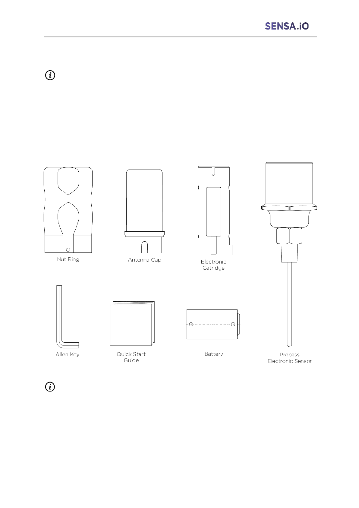
The SENSAIO Sensor includes the following parts:
• 1 Temperature device
• 1 Battery SAFT M20 EX SV
• 1 Quick Start Guide
• 1 Allen screw M5
NOTE
The quick start guide provides a step-by-step description of how to set the device. This can
be found in the box delivered with the device.

LoRaWAN Temperature Sensors User Manual | English
613-00003
Page 11 of 56
Installation
Wall mounting
Attach the wall mount to the wall using 2 screws (10 mm (0.39 inch)).
Pipe mounting
Attach the pipe mount to the pipe using 2 pipe clamps (. 10 mm (0.39 inch)). The pipe mount
can be attached to a pipe with a maximum diameter of 63.5 mm (2.5 inch).
NOTE
The probe must be mounted with sufficient thermal insulation between the process and
the main housing of the device such that thermal backflow from the process does not
cause the temperature of the enclosure to exceed the maximum specified ambient
temperature. This can be achieved, for example, with suitable heat insulation or a neck
tube of suitable length.
• During installation, ensure no obstructions surrounding the antenna radiation patterns.
We recommend enough clearance surrounding the device.
• Position the gateway so that the transmission power of the device is used optimally.
For this, the following recommendations should be observed:
■ Depending on the application, a gateway for indoor or outdoor use should be selected
■ Between the instrument antenna and the gateway, there should be as few barriers as
possible (e.g. walls and hills)
LoRaWAN Temperature Sensors User Manual | English
613-00003
Page 12 of 56
■ The radiation characteristics of the antenna must be taken into account when positioning
the gateway.
■ If the measuring instruments are located on one level, vertical mounting of the LoRa®
antenna on the gateway is recommended.
■ The location should ideally be in the middle of the area to be covered.
■ Ensure that the gateway is mounted at a sufficient height and is not covered by
anything in the immediate vicinity.
NOTE
Signal coverage can impact the life of the battery. Make a test survey prior installing the
device
3.1 Replacing the battery
NOTE
Only use SAFT M20 EX SV 3 V battery only (Part# 142187103) with this device.
NOTE
Only carry out battery replacement procedure in a dry environment
NOTE
The device can only be powered by the SAFT M20 EX SV battery. The battery can be buy to
any SAFT authorized reseller only. https://www.saftbatteries.com/about-us/who-saft/saft-
worldwide
CAUTION
There is a risk of explosion if the battery is replaced by an incorrect type. The battery must
be replaced by qualified personnel only.
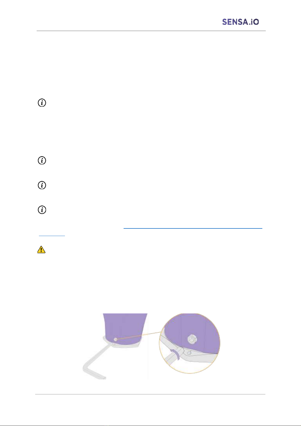
Procedure
1. Loosen the allen screw on the side of the nut rings with M5 Allen key provided in the
box

LoRaWAN Temperature Sensors User Manual | English
613-00003
Page 13 of 56
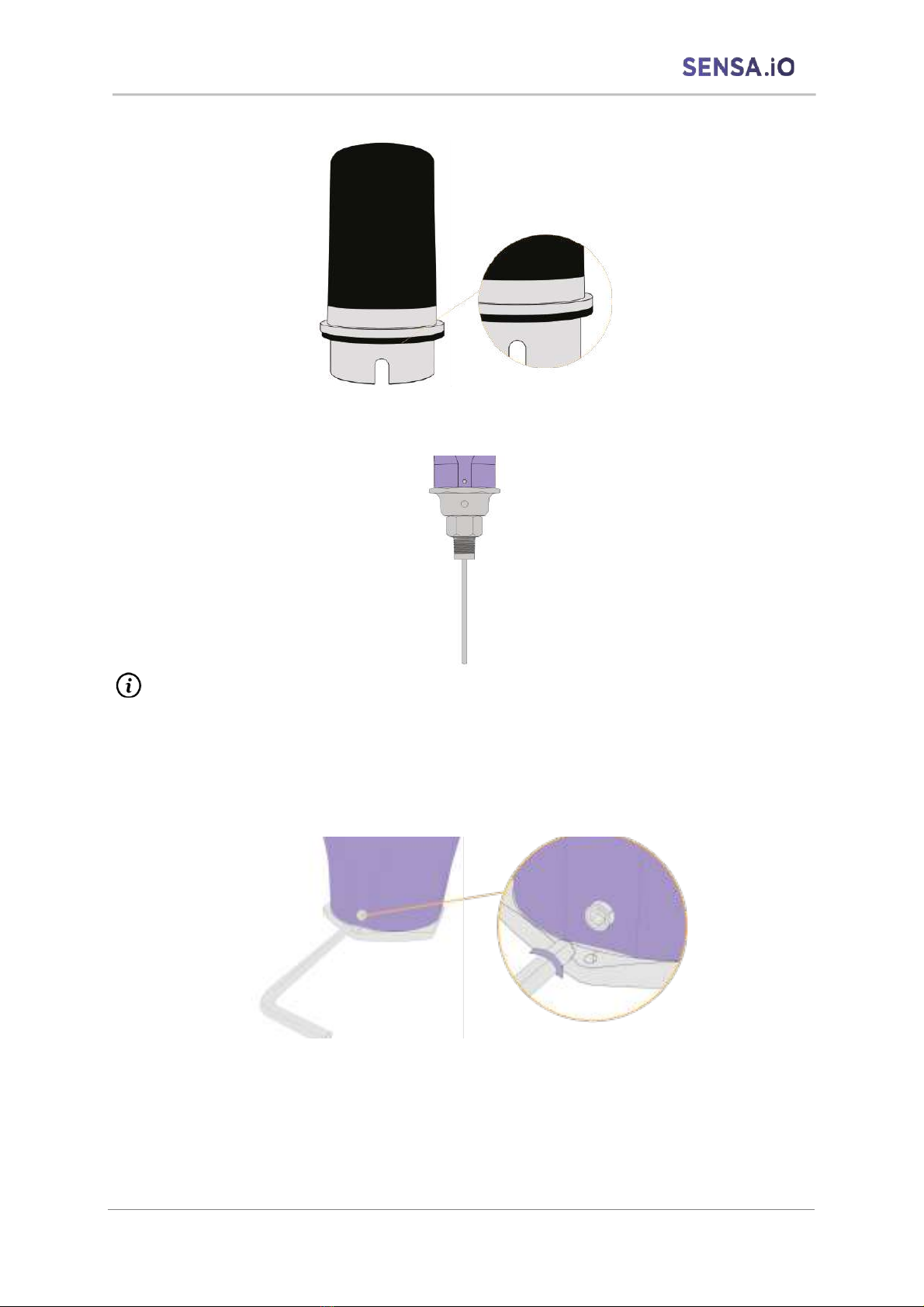
2. Unscrew the nut ring
3. Remove the antenna cap carefully without dropping the electronic cartridge.
4. Insert the battery inside the electronic cartridge
LoRaWAN Temperature Sensors User Manual | English
613-00003
Page 14 of 56
5. Ensure the sealing gasket is there and not damage
6. Fully tighten the nut ring
NOTE
Make sure nut ring is completely screw without gap otherwise device will not be power
on. The device switches automatically and advertise below for 30s before going to
LoRaWAN mode.
7. Screw back the allen screw on the side of the nut ring
8. When battery has been replaced and device is power-on, using Sensalink Mobile, go
to status/battery and click on “Replace”. Please refer to section 4.1 Sensalink Mobile.

LoRaWAN Temperature Sensors User Manual | English
613-00003
Page 15 of 56
WARNING
Danger for electronic components through electrostatic discharge (ESD)
Improper handling of electrical components can destroy or damage them.
• When the battery compartment is open, e.g. when changing the battery, sufficient ESD
protection must be ensured
• Battery replacement must be performed by trained personnel only
• Battery has to be replaced only when gas atmosphere is not present. We recommend
to use portable gas detector when performing this action.
3.2 Sealing procedure
NOTE
Sealing gasket should be replaced if any damaged is observed and free of moisture with
genuine gasket only. Please contact manufacturer or authorized reseller for order.
LoRaWAN Temperature Sensors User Manual | English
613-00003
Page 16 of 56
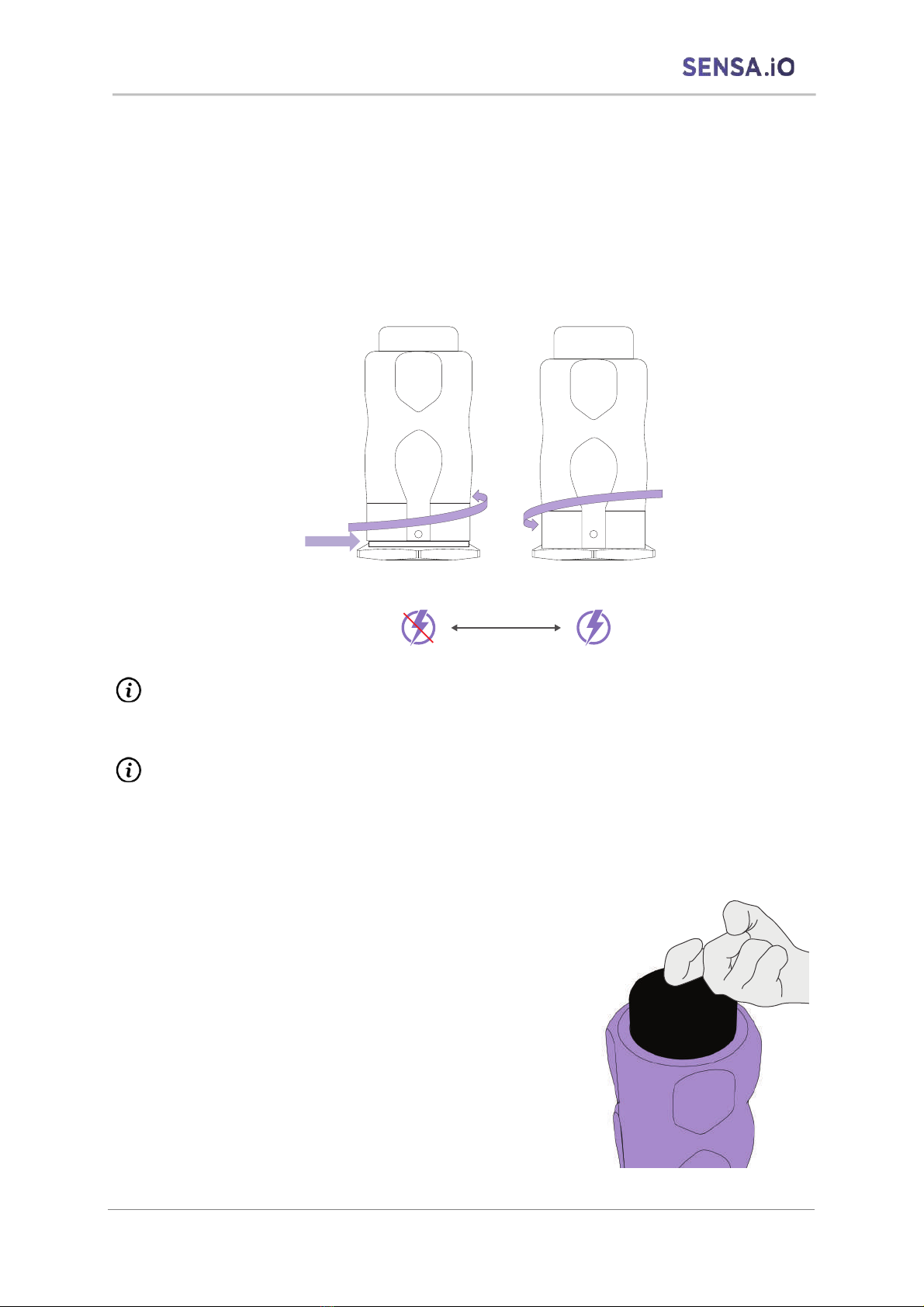
3.3 Operate the device
ON/OFF mode
When device is delivered it is POWER OFF. A 5mm or 1/4-inch clearance will appear between
the nut ring and the process connection as illustrate below. See below illustration.
To POWER ON the device, simply fully screw the nut ring until there is no more clearance
between the nut ring and the process.
NOTE
Device will automatically start advertising in BLE® mode during 30s after POWER ON
NOTE
It’s mandatory to POWER OFF the device during storage, or transportation. If device if
POWER ON it will automatically try to connect to a LoRaWAN gateway and drag battery
down unnecessarily.
BLE® Advertising mode
This mode is only active 30s after POWER ON the
device. Double tap the antenna cap with your hand
firmly as shown in the illustration to wake up the device
in BLE® advertising mode. The device will advertise for
30s prior switching to LoRaWAN mode.
5mm or ¼-inch
clearance gap
T
a
p
2
x

LoRaWAN Temperature Sensors User Manual | English
613-00003
Page 17 of 56
BLE® Beacon mode
To active the beacon mode, Beacon mode is always-on mode. Device will keep advertising (1
data per second) and data can be collected using Bluetooth® Gateway. This mode is used for
data extraction on site or any application requiring live data pulling. Default sampling rate is
set to 1 data sample per second. Refer to section 4.1 Sensalink Mobile to active Beacon Mode.
NOTE
Be aware that beacon mode will drag battery down quickly. (Approximately 90 Days)
BLE® Beacon and advertising mode are taking into account in the battery life calculation.
LoRaWAN® mode
LoRaWAN mode is the main operating mode with full functionality of the LoRa
communication. The LoRaWAN® mode is activated automatically when the 30s Bluetooth®
advertising mode has stopped. LoRaWAN® parameters can be modified either using
SENSALINK® Mobile application or via LoRaWAN® downlink.
NOTE
Device will automatically switch to LoRaWAN mode after 30s BLE® advertising mode end.
NOTE
No data will be send via LoRaWAN® mode when BLE® Beacon mode or advertising mode
is active.
3.4 Battery life
The battery life is displayed as a percentage value vue LoRaWAN® transmitted or locally by
Bluetooth® using SENSALINK® mobile application. The calculation of the approximate value
is based on an internal algorithm measuring each processing time with compensated in
temperature to -10Deg, 10DegC, 30DegC and 50DegC. Since the battery life is influenced by
many factors, this value is only an approximation. At value below 25% a battery change is
recommended. If the battery is completely discharged, no more value is transmitted via the
radio interface.
Here below an estimated battery life calculation for Sensa.io Temperature device:
Tests conditions
SensaIO Sensor
LoRa TX periodicity
SensaIO lifetime in SF7
SensaIO lifetime in SF12
Disclaimer
Product storage before
use: 1 year maximum
Measurements have
been done on firmware
version 1.1 at 0°C in
May 2021
TEMPERATURE
288 LoRa TX per day (every 5’)
8 years and 262 days
1 year and 147 days
Due to the internal
chemistry of the
battery, the autonomy
results beyond 7 years
should be considered as
highly approximate.
144 LoRa TX per day (every 10’)
9 years and 311 days
2 years and 181 days
96 LoRa TX per day (every 15’)
10 years and 109 days
3 years and 136 days
72 LoRa TX per day (every 20’)
10 years and 197 days
4 years and 33 days
48 LoRa TX per day (every 30’)
10 years and 288 days
5 years and 72 days
32 LoRa TX per day (every 45’)
10 years and 351 days
6 years and 125 days
24 LoRa TX per day (every 60’)
11 years and 19 days
7 years and 46 days
16 LoRa TX per day (every 90’)
11 years and 52 days
8 years and 48 days
12 LoRa TX per day (every 120’)
11 years and 69 days
8 years and 273 days
Tests conditions
SensaIO Sensor
LoRa TX periodicity
SensaIO lifetime in SF7
SensaIO lifetime in SF12
Disclaimer
Product storage before
use: 1 year maximum
Measurements have
been done on firmware
version 1.1 at 25°C in
May 2021
TEMPERATURE
288 LoRa TX per day (every 5’)
6 years and 352 days
1 year and 127 days
Due to the internal
chemistry of the
battery, the autonomy
results beyond 7 years
should be considered as
highly approximate.
144 LoRa TX per day (every 10’)
7 years and 245 days
2 years and 120 days
96 LoRa TX per day (every 15’)
7 years and 343 days
3 years and 27 days
72 LoRa TX per day (every 20’)
8 years and 29 days
3 years and 240 days
48 LoRa TX per day (every 30’)
8 years and 83 days
4 years and 190 days
32 LoRa TX per day (every 45’)
8 years and 119 days
5 years and 131 days
24 LoRa TX per day (every 60’)
8 years and 138 days
5 years and 332 days
16 LoRa TX per day (every 90’)
8 years and 157 days
6 years and 214 days
12 LoRa TX per day (every 120’)
8 years and 167 days
6 years and 359 days

LoRaWAN Temperature Sensors User Manual | English
613-00003
Page 18 of 56
3.5 Installation of Temperature Sensor
WARNING
Ensure the suitability of the temperature measuring instrument and its media resistance
within the application through proper choice of materials. Non-observance can result in
serious injury and/or damage to property and the environment.
CAUTION
Damage to the instrument
In order to prevent any damage to the instrument, follow below recommendation:
• The device must not be subjected to any mechanical loading
• Make sure the threaded connections are clean and undamaged
• The device should be installed in such a way that process-related electrostatic charges
can be excluded.
• Ensure the antenna cap is not damaged
• To avoid electrostatic charge build-up, it must not be rubbed or cleaned with solvents
or anti-static cloth.
• When cleaning the device, make sure that the cleaning agent used does not corrode
the housing surface and the gaskets.
LoRaWAN Temperature Sensors User Manual | English
613-00003
Page 19 of 56
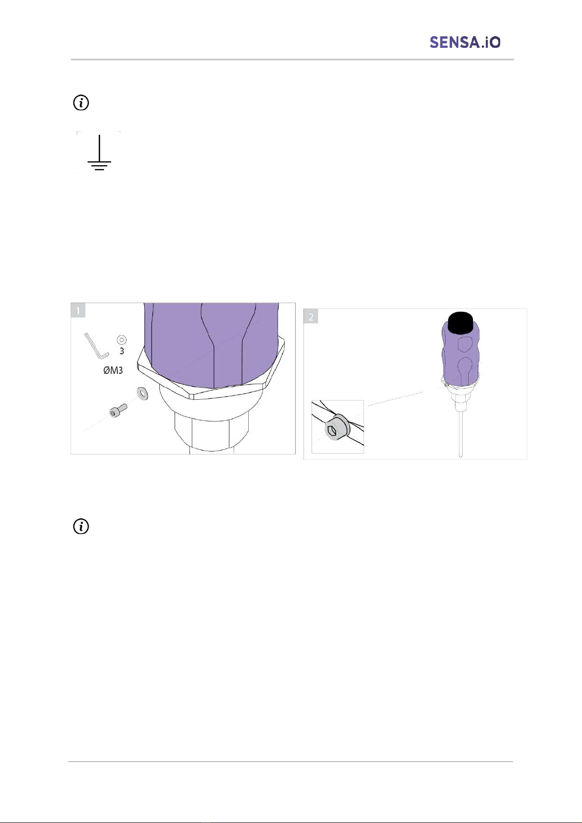
3.6 Grounding
NOTE
Functional grounding terminal
This symbol identifies the terminal which is intended for connection to ground
to mitigate electromagnetic interference (EMI). Device should be grounded or
earthed in accordance with national and local electrical codes.
It is necessary to ensure conductivity (Resistance less than 0.2MΩ) between the device and
equipment. Grounding impedance equal or less of 5Ω is recommended. In order to ensure
grounding through the process connection while maintaining the seal can be done in several
ways.
If continuity between the ground terminal and the ground electrode cannot be ensured, use
the following cables and a round crimp terminal for M3 grounding terminal with insulation
sleeve as per Figure below.
NOTE
• While using Teflon tape properly tighten and measuring the resistance afterwards
• Insulated Cables for industrial equipment such as;
o 600V polyvinyl chloride insulated wires AWG 14 to 13 (2 to 2.6 mm2)
o In each case, it is recommended to ensure that the connection is made by
measuring the ground resistance.
Table of contents


