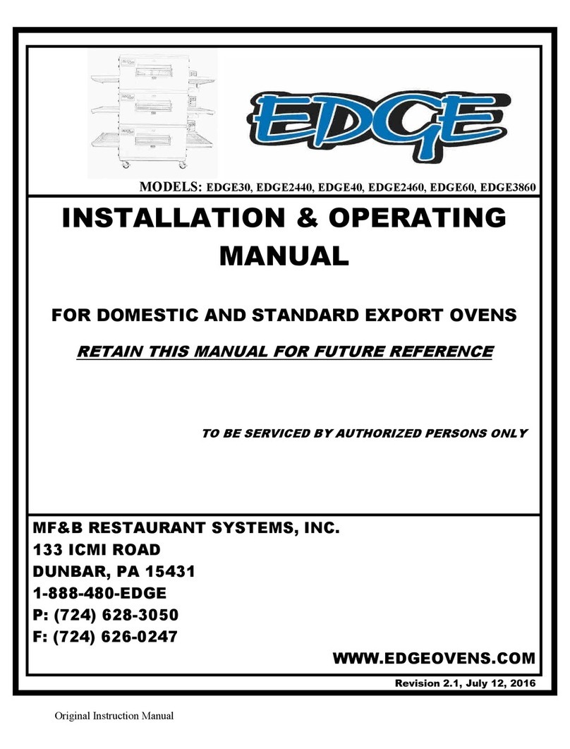
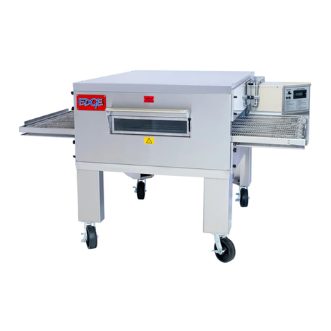
Edge EDGE-1830 User manual

Original Installation
Operation & Service Manual
(2C) Chassis, 2022
US Domestic
Retain This Manual for Future Reference
To Be Serviced by Authorized & Qualied Personnel Only
www.edgeovens.com
MF&B Restaurant System, Inc.
119 ICMI Road, Suite 300,
Dunbar, PA, 15431, USA
+1.724.628.3050
+1.888.480.EDGE
For use with the following EDGE Gas Ovens:
EDGE-1830 EDGE-2440
EDGE-3240 EDGE-2460
EDGE-3260 EDGE-3260S
EDGE-3860 EDGE-4460
EDGE-4460S EDGE-3270
EDGE-3870
S
A
N
I
T
A
T
I
O
N
L
I
S
T
E
D
3133776 1312 8510
CD-941-408-3REV: 22.2

2[email protected] Technical Support: +1 (724) 628 3050
PREFACE
Do not store or use gasoline or other ammable vapors or liquids in the vicinity of this
or any other appliance.
Improper installation, adjustment, alteration, servicing, or maintenance can result
in property damage, injury, or death. Read this entire manual and ensure that you
thoroughly understand all instructions before installing, operating, or servicing this
equipment.
Keep the appliance free and clear of combustibles. Provide a minimum clearance of 6
inches between all surfaces of the appliance and combustible material. Do not use
aerosols within the area of the operating appliance.
Do not obstruct the ow of combustion or ventilation air to and from the oven. There
should never be any obstructions on or around the oven that could hamper the ow of
combustion or ventilation air to or from the oven. Any changes to the area where the
oven is installed must not affect the combustion or ventilation air to and from the oven.
WARNING
IMPORTANT
Retain all shipping materials until you are certain that the oven has not been damaged
(either externally or internally) during shipment. Thoroughly inspect the oven on receipt
for both external and internal damage. It is solely the customer’s responsibility to report
any shipping damage to the freight company.
Oven installation, including electrical and gas connections, oven placement, and
ventilation must comply with all applicable national and local codes. National and local
codes supersede the recommendations, requirements, and guidelines contained in the
manual.
The purchaser of this equipment is required to prominently post instructions to be
followed should the user smell gas. This information shall be obtained from the local
gas supplier.
WARNING
WARNING
WARNING
NOTICE
NOTICE
WARNING AND SAFETY INFORMATION
This appliance is not intended for use by persons (including children) with reduced
physical, sensory or mental capabilities, or lack of experience and knowledge, unless
they have been given supervision or instruction concerning use of the appliance by a
person responsible for their safety.
NOTICE

i
PREFACE
WARNING AND SAFETY INFORMATION
All service technicians of the EDGE Oven must read this summary and all warnings and cautions in the manual.
Any internal part(s) replacement or assembly and reassembly must be performed by qualied service personnel
with a good understanding of mechanical, gas and electrical components. If difculties arise in locating a qualied
service person, please contact your EDGE oven distributor or MF&B for assistance in locating qualied personnel
to assist you.
DEFINITIONS & SYMBOLS
A safety instruction (message) includes a “Safety Alert Symbol” and a signal word or phrase such as HOT,
WARNING or CAUTION. Each signal word has the following meaning:
Indicates a potentially hazardous situation that, if not avoided, can result in serious
injury or death.
WARNING
Indicates conditions that could damage equipment or property.
CAUTION
HOT
Indicates conditions that may result in a burn injury.
IMPORTANT
Indicates an area or subject relating to compliance of a local regulation, emphasizing
best practice of adherence to stated regulation. Can also indicate a recommended
course of action.
NOTICE
Indicates an area or subject of special merit, emphasizing either the product’s
capability or common errors in operation or maintenance.

ii [email protected] Technical Support: +1 (724) 628 3050
PREFACE
WARNING AND SAFETY INFORMATION
US CUSTOMERS
Oven installation must comply with local codes or, if local codes do not exist, with the
National Fuel Gas Code, ANSI Z223.1/NFPA 54.
This appliance must be electrically grounded in accordance with local codes, or if local
codes do not exist, with the National Electrical Code, ANSI/NFPA 70.
This appliance and its individual manual shutoff valves must be disconnected from the
gas supply piping system during any pressure testing of gas supply piping at pressures
exceeding 1/2 psi (3.5 KPa).
NOTICE
IMPORTANT
CANADIAN CUSTOMERS
Oven installation must comply with local codes or, if local codes do not exist, gas oven
installation must comply with the Natural Gas Installation Code, CAN/CGA-B149.1, or the
Propane Gas Installation Code, CAN/CSA-B149-2, as applicable.
This appliance must be electrically isolated in accordance with local codes, or if local
codes do not exist, with the Canadian Electrical Code, CSA C22.2.
IMPORTANT
EXPORT CUSTOMERS
Oven installation must comply with local codes. This appliance must be electrically
grounded in accordance with local codes.
IMPORTANT
Always check for leaks after making any gas supply piping connections or performing
any service on the oven.
WARNING
The installer of this oven must contact local building and re ofcials concerning
inspections and installation requirements of this oven and its ventilation system.
NOTICE
Installing any part(s) not provided by the Edge oven OEM shall void the warranty and
release the OEM from any and all liabilities.
NOTICE

iii
PREFACE
Appliance is NOT to be cleaned with jets of water. End plugs and oven back are not to be
submerged.
NOTICE
NORTH AMERICA CUSTOMERS OVENS EQUIPPED WITH CASTERS:
When this appliance is installed with casters, it must be installed with the casters
supplied, a connector complying with ANSI Z21.69 (CSA 6.16), a quick-disconnect
device complying with ANSI Z21.41 (CSA 6.9), and a mechanism to limit movement of the
appliance without straining the connector or its associated piping system.
Adequate means must be provided to limit movement of the appliance without
depending on the connector, quick-disconnect device, or associated piping to limit
appliance movement.
The restraining device must be attached to the mounting eye located on the oven rear
side of the oven base assembly.
IMPORTANT
EXPORT CUSTOMERS OVENS EQUIPPED WITH CASTERS
When this appliance is installed with casters, it must be installed with the casters
supplied, a quick-disconnect device, and a mechanism to limit movement of the
appliance without straining the connector or its associated piping system.
Adequate means must be provided to limit movement of the appliance without
depending on the connector, quick-disconnect device, or associated piping to limit
appliance movement.
The restraining device must be attached to the mounting eye located on the oven rear
side of the oven base assembly.
IMPORTANT
To prevent damage to the oven and personal injury or death, the voltage, phase and
grounding of the electrical supply must be inspected and veried prior to energizing.
WARNING
NORTH AMERICA CUSTOMERS
This appliance is equipped with a three-prong (grounding) plug and must be connected
to a properly grounded three-prong receptacle. This is to protect you from a possible
shock hazard.
DO NOT remove the grounding prong from this plug or use any form of adapter to plug
the appliance into a standard two-prong receptacle.
Use only the cord set supplied by the oven OEM, or a direct replacement cord set
purchased from the oven OEM. Other cord sets may present a re and/or electric shock
hazard.
WARNING
WARNING AND SAFETY INFORMATION

iv [email protected] Technical Support: +1 (724) 628 3050
PREFACE
GENERAL CAUTIONS
WARNINGS RELATED TO THE OPERATING ENVIRONMENT
CAUTION
To avoid a possible explosion, do not service the product in an atmosphere where explosive gases
or fuel vapors are present. Verify all gas valves are in the OFF position and that enough ventilation is
present to evacuate any unburnt gases.
WARNINGS RELATED TO ELECTRIC SHOCK
Electricity can seriously injure or kill. Disconnect the power cord for the electrical outlet or lock out
the service disconnect before servicing this equipment.
Always ensure an earth ground is correctly connected to the equipment. When troubleshooting
live electrical circuits, use care and best practices to ensure an electrical pathway is not completed
through the body.
WARNING
WARNING
HOT
WARNINGS RELATED TO HOT SURFACES
Serious injury may occur from contact to hot surfaces. Allow adequate cooling time of the appliance
prior to service or maintenance.
In situations where handling of the appliance or its parts in unavoidable, use thermal protective
gloves to protect the hands, wear long shirts and pants to protect arms and legs. Do not attempt to
“test” the temperature of surfaces by touch.
GENERAL CAUTIONS
•To prevent possible damage, do not use sharp or hard objects on interface screen, use only
ngertips.
•Mobile RF communications equipment and high frequency LED lighting may affect the
performance of this equipment as dictated by FCC regulations.
• The power cord must be disconnected from the AC power before cleaning, maintaining, servicing,
or transporting.
• The gas supply line must be disconnected from the oven before cleaning, maintaining, servicing,
or transporting.
•There are NO parts of the oven that are designed to withstand impacts. Damage will result.
CAUTION
ELECTROSTATIC DISCHARGE (ESD)
•Electrostatic discharge (ESD) can damage or destroy electronic components. Handle static
sensitive components using safe practices.
• Assume that all electrical and electronic components of the appliance are static sensitive.
Electrostatic discharge is a sudden current owing from a charged object to another object or
to ground. Electrostatic charges can accumulate on common items such as foam drinking cups,
cellophane tape, synthetic clothing, untreated foam packaging material, and untreated plastic bags
and work folders, to name only a few.
Electronic components and assemblies, can be permanently damaged or destroyed when near or in
contact with electrostatic charged objects. When you handle components or assemblies assume that
they are static-sensitive and handle them accordingly.
IMPORTANT

v
PREFACE
•Always use techniques to protect personnel and equipment from electrostatic discharge. ESD
Wrist or Heal straps are recommended for appliance and personal safety.
•Remove static-sensitive components and assemblies from their static-shielding bags only when
you are stationary and prepared to immediately install the component.
•Remove or install static-sensitive components and assemblies with appliance power
disconnected.
•Insert & seal static-sensitive components and assemblies into their original static-shielding bags.
•Always test your ESD strap before beginning any disassembly or assembly procedures.
ELECTROSTATIC DISCHARGE (ESD) - CONTINUED
IMPORTANT
Please retain this manual for future reference.
NOTICE
GENERAL CAUTIONS
The oven electrical wiring diagram is located inside the control cabinet, on the underside
of the control cabinet lid.
NOTICE

vi [email protected] Technical Support: +1 (724) 628 3050
PREFACE
LIMITED WARRANTY
MF&B Restaurant Systems, Inc. warranties this product to be free from defects in material and workmanship
for a period of:
• ve (5) years from the date of installation or sixty-two (62) months from the purchase date, whichever
occurs rst. (U.S.A. Only)
MF&B Restaurant Systems, Inc., hereinafter referred to as “MF&B”, warrants equipment manufactured by it to
be free from defects in material and workmanship for which it is responsible.
MF&B’s obligation under this warranty shall be limited to replacing or repairing at MF&B’s option, without
charge, any part found to be defective and any labor and material expense incurred by seller in repairing
or replacing such part. MF&B shall have no liability, whether in contract, tort, negligence, or otherwise, with
respect to non-MF&B manufactured products.
Denial of access or services upon the arrival of an authorized service technician or delivery company will
release MF&B of any and all warranty obligations. Any incurred costs as result of denial of services shall be the
responsibility of the Buyer.
WHO IS COVERED
This Limited Warranty applies to products purchased for the North American market, the original purchaser in
the original install location and is not transferable unless written consent is obtained from MF&B.
LIMITATIONS OF LIABILITY
The preceding paragraphs set forth the exclusive remedy for all claims based on failure of, or defect in,
products or services sold hereunder, whether the failure or defect arises before or during the warranty period,
and whether a claim, however instituted, is based on contract, indemnity, warranty, tort (including negligence),
strict liability, implied by statute, common-law or otherwise, and MF&B its servants and agents shall not be
liable for any claims for personal injuries, incidental or consequential damages or loss, howsoever caused.
Upon the expiration of the warranty period, all such liability shall terminate.
The foregoing warranties are exclusive and in lieu of all other warranties, whether written, oral, implied or
statutory no implied warranty of merchantability or tness for particular purpose shall apply. MF&B does not
warrant any products or services of others.
Limited Warranty is valid only if the equipment is installed in accordance with the supplied
commissioning documentation.
BUYER RESPONSIBILITIES
• The oven and crate must be carefully inspected at the time of receipt. Any damage during freighting is to be
reported immediately to the freighter, MF&B Restaurant Systems, Inc (T/A EDGE ovens), and documented
on the Bill of Lading.
• The Buyer shall ensure that the ovens be installed and operated in accordance with the Installation and
Operation Manual provided with the oven and adheres to local re and building codes.
• The Buyer shall verify that the ovens are installed in accordance with the ventilation section of the
Installation and Operation Manual.
• This warranty shall not excuse the owner from properly maintaining the oven in accordance with the
maintenance section of the Installation and Operation Manual. All claims as result of failure to maintain the
oven shall be the responsibility of the Buyer.
WARRANTY

vii
PREFACE
• Completed commissioning documentation, provided with the oven, MUST be submitted to MF&B
Restaurant Systems, Inc (T/A EDGE ovens), on completion of commissioning and prior to oven entering
service.
• The gas, electric services and extraction system must be connected to the oven and installed by licensed
contractors in accordance with the OVEN VENTILATION and FINAL CONNECTIONS sections of the
Installation and Operation Manual.
• Should any such defect be discovered, Buyer is responsible to notify MF&B Restaurant Systems, Inc (T/A
EDGE ovens). Upon notication, MF&B will arrange for necessary repairs to be made by an authorized
service agent.
• Failure to contact MF&B prior to contacting a repair company for warranty work voids any and all
warranties.
WHAT IS NOT COVERED (EXCLUSIONS)
• Freight damage
• Overtime charges.
• Failures as the result of improper or erratic supply voltages, gas pressure, contaminated gas or improper
utility connections.
• Adjustments of or calibration of air ow, gas valve, temperature and fasteners.
• Any part that becomes defective as a result of moisture and/or other contaminants
• Filters
• Fuses and Breakers
• Capacitors
• Gas Hoses / Power Cords
• Conveyor belt assembly
• Powder Coated surfaces
• Normal maintenance or adjustments
• This warranty shall not apply if the equipment or any part is damaged as a result of accident, casualty,
alteration, infestation, misuse, abuse, improper cleaning, improper installation, improper operation,
unauthorized repair or alteration, natural or man-made disasters or otherwise acts of God.
Warranty claims will be voided and/or deemed chargeable under the following conditions:-
• All overtime charges are chargeable by MF&B.
• Required service area around ovens is less than 6" in all directions.
• Inhibited oven manoeuvrability. If the oven has not been commissioned with a quick connect gas hose,
casters or the oven is impeded by any obstacles (hood, surrounding appliances, kitchen supplies etc)
preventing 360° access to the oven and its controls.
• Over temperature of oven control cabinet as a result of poor ventilation, failure to clean or replace cooling
fan lter or obstruction of control cabinet cooling fan.
• Denial of services.
• If service work is performed and is determined to not be covered under the factory warranty MF&B will
invoice the oven owner directly. If the invoice is not paid within 30 days this will void the factory warranty.
WARRANTY CLAIM PROCEDURE
See following page for detailed warranty claim procedure.

viii [email protected] Technical Support: +1 (724) 628 3050
PREFACE
•MF&B must be informed immediately should any defect be identied.
•Pre-authorization is required prior to any warranty work.
To initiate a warranty call, the following information must be provided to the EDGE technical team:-
Oven log le must be exported to the USB ash drive provided with the oven and emailed to the EDGE
service team or uploaded via the EDGE app or website. See instructions on how to download the oven
data log le below and on the following page.
Oven Serial Number (located on data plate on oven control cabinet)
Store Name
Contact Name
Contact Number
Oven Location (full address)
Detailed Nature of Problem
WARRANTY CLAIM PROCEDURE
OVEN DATA LOG FILE EXPORT
The EDGE G2 control system, records and logs all errors seen and unseen, as well as component I/O’s,
operator adjustments and oven interactions. It does this for a period of 14-21 days.
This EXPORT feature will transfer OVEN DATA LOG FILES stored in the control system to a USB ash drive,
for the purpose of off-site analysis by the EDGE service team,. The transferred les can be sent via email to
FIGURE 1-1
1. Locate the USB port on the rear side of the oven control cabinet,
adjacent to the cooling fan lter. (Figure 3-1)
2. Remove the USB dust cover by unscrewing the cover.
3. Insert the USB ash drive into the USB port.
+1-888-480-3343 (TOLL FREE)
+1-724-628-3050 (LOCAL)
All EDGE G2 ovens are supplied with a 4 way USB ash drive. It is
provided and found as part of you service manual pack.
NOTICE

ix
PREFACE
OVEN DATA LOG FILE EXPORT (CONTINUED)
If exporting multiple log les from unique oven decks, each oven data log le must be
exported and transferred from the USB ash drive before attempting a subsequent EXPORT
from a different oven. The control system will overwrite any previously exported oven data
les on the USB storage device.
NOTICE
EXPORT
✔
✖
6
6. Use the UP () or DOWN () arrows to navigate to the
EXPORT option.
7. Touch the tick (✔) icon to initiate the oven data log EXPORT.
5
8. The oven control system will begin the EXPORT of the OVEN
DATA LOG FILE to the USB ash drive. During the export
procedure normal oven operation will be interrupted.
It is important that the EXPORT procedure successfully
completes. If it does not, SHUT DOWN the oven and unplug
from the mains power and wait thirty (30) seconds before
restarting the oven and retrying the EXPORT procedure.
9. Once completed, remove the USB ash drive from the USB port
and install the dust cover.
10. Unplug the oven from mains power and wait thirty (30) seconds
before restarting the oven and returning it to an operating state.
Downloading MC1 50%
Do not remove USB
Complete
Please Remove USB
MANUAL
470°F
F-L►R
06:00
R-L►R
04:30
4. Access the INFORMATION MENU by swiping the screen to
change to the SYSTEM MENU screen.
5. Touch the INFORMATION icon to navigate to the
INFORMATION MENU.
5
4
For detailed instructions of how to email your oven data log le, please see the EMAILING OVEN DATA LOG
FILE(S) in the OVEN INFORMATION section of this manual.

x[email protected] Technical Support: +1 (724) 628 3050
TABLE OF CONTENTS
WARNING AND SAFETY INFORMATION ..........................................................................i
GENERAL CAUTIONS ...................................................................................................iv
LIMITED WARRANTY ....................................................................................................................vi
warranty claim procedure...........................................................................................viii
Oven Data Log File Export ........................................................................................................................... viii
OVEN DESCRIPTION......................................................................................................1
OVEN COMPONENTS .....................................................................................................2
OVEN DIMENSIONS & SHIPPING WEIGHTS ...................................................................3
Single Stack.................................................................................................................................................... 3
Double Stack .................................................................................................................................................. 4
Triple Stack..................................................................................................................................................... 5
OVEN SHIPPING DIMENSIONS.......................................................................................6
OVEN GAS SPECIFICATIONS.........................................................................................7
US Domestic (120V/60Hz) ............................................................................................................................. 7
Burner Blower Air Shutter Setting................................................................................................................... 7
World Models (CE) ......................................................................................................................................... 8
GAS OVEN ELECTRICAL SPECIFICATIONS ...................................................................9
BEST PRACTICE GAS & ELECTRICAL CONFIGURATION ............................................ 10
OVEN VENTILATION .................................................................................................... 11
Ventilation Requirements.............................................................................................................................. 11
Exhaust CFM Rates ..................................................................................................................................... 11
Make Up Air (MUA)....................................................................................................................................... 11
INSTALLATION INSTRUCTIONS ................................................................................... 12
Foreword ...................................................................................................................................................... 12
Warning & Safety Information....................................................................................................................... 13
Tools & Equipment Required ........................................................................................................................ 13
OVEN ASSEMBLY......................................................................................................... 14
Unpacking your Oven ................................................................................................................................... 14
Belt Assembly ............................................................................................................................................... 14
Base, Legs & Castors Assembly .................................................................................................................. 15
Assembling Your Oven with Approved EDGE Lifting Equipment.................................................................. 16

Technical Support: +1 (724) 628 3050 xi
Spinning Oven From Delivery Skid Or Edge Delivery Cart .......................................................................... 16
Main Blower Harness Connection & Cover Install........................................................................................ 19
Stacking Your Oven ...................................................................................................................................... 20
Conveyor Belt & Finger Panel Removal And Inspection .............................................................................. 25
Finger Panel Assemblies Explained ............................................................................................................. 29
Columnating Panel Options.......................................................................................................................... 29
Standard Conveyor Drive System Assembly................................................................................................ 31
Split-Belt Conveyor Drive System Assembly ................................................................................................ 34
Conveyor Belt Crumb Pans .......................................................................................................................... 39
Belt Stops ..................................................................................................................................................... 39
Chain Guard ................................................................................................................................................. 40
Heat Shields ................................................................................................................................................. 41
End Panel Bafes (Optional) ........................................................................................................................ 42
Cool Wall ...................................................................................................................................................... 43
Type 1 Cool Wall Installation .................................................................................................................. 43
Type 2 Cool Wall Installation .................................................................................................................. 44
FINAL CONNECTIONS.................................................................................................. 45
Restraint Cable............................................................................................................................................. 45
Electrical ....................................................................................................................................................... 46
North America (US Domestic)................................................................................................................. 46
World (Export & CE) ............................................................................................................................... 46
Gas ............................................................................................................................................................... 47
Valve Specications...................................................................................................................................... 47
Gas Connection............................................................................................................................................ 48
MANIFOLD PRESSURE ADJUSTMENT ......................................................................... 50
AIR SHUTTER CONFIRMATION & ADJUSTMENT ......................................................... 51
OVEN INITIAL START-UP ............................................................................................. 52
Start-Up Procedure....................................................................................................................................... 52
Warranty Activation....................................................................................................................................... 52
DECOMMISSIONING & DISPOSAL ............................................................................... 52
FIRE SUPPRESSION .................................................................................................... 53
Pipe & Bracket Install ................................................................................................................................... 54
TABLE OF CONTENTS

xii [email protected] Technical Support: +1 (724) 628 3050
PREFACE
Heat Shield Install......................................................................................................................................... 58
Final Connections......................................................................................................................................... 59
Nozzle Recommendation, Position & Aim-Point........................................................................................... 60
OVEN OPERATION ....................................................................................................... 61
G2 Controls .................................................................................................................................................. 61
UI Touch Screen ........................................................................................................................................... 61
Main Operating Screen (Default Screen)................................................................................................ 61
System Menu.......................................................................................................................................... 61
Cleaning The UI Touch Screen............................................................................................................... 62
Entering Customer Pin............................................................................................................................ 62
Basic Operation ............................................................................................................................................ 63
Power Up Your Oven .............................................................................................................................. 63
Manual Mode.......................................................................................................................................... 63
Temperature Adjustment (Manual Mode)................................................................................................ 64
Bake Time Adjustment (Manual Mode)................................................................................................... 65
Power Down ........................................................................................................................................... 65
Fan Speed Adjustment (Manual Mode) .................................................................................................. 66
Advanced Operation..................................................................................................................................... 67
Recipes................................................................................................................................................... 67
Creating A New Recipe (From Manual Mode) ........................................................................................ 67
Selecting A Saved Recipe Or Manual Mode........................................................................................... 69
Editing A Saved Recipe .......................................................................................................................... 70
Deleting A Saved Recipe ........................................................................................................................ 70
Oven Settings ............................................................................................................................................... 71
Accessing The Settings Menu ................................................................................................................ 71
Reversing Belt Direction ......................................................................................................................... 72
Temperature Unit Alteration (°C/°F) ........................................................................................................ 73
Changing Customer Pin From Factory Default....................................................................................... 74
Recipe Download.................................................................................................................................... 75
Recipe Upload ........................................................................................................................................ 76
Control System Software Update ........................................................................................................... 77
Oven Information .......................................................................................................................................... 79
TABLE OF CONTENTS

xiii
PREFACE
Accessing The Information Menu ........................................................................................................... 79
Oven Error Alarms .................................................................................................................................. 80
Oven System Information ....................................................................................................................... 81
Software Version Verication.................................................................................................................. 82
Oven Data Log File Export ..................................................................................................................... 83
Emailing Oven Data Log File(s).............................................................................................................. 84
PREVENTATIVE MAINTENANCE................................................................................... 85
Oven Cleaning & Maintenance Schedule..................................................................................................... 85
Daily........................................................................................................................................................ 85
Weekly .................................................................................................................................................... 85
Monthly ................................................................................................................................................... 85
Semi-Annually......................................................................................................................................... 85
Preventative Maintenance ............................................................................................................................ 86
Cleaning Surface Areas................................................................................................................................ 87
Inspect Or Clean Cooling Fan Filter ............................................................................................................. 88
Empty & Clean Crumb Pan .......................................................................................................................... 89
Inspect, Brush & Remove Debris From Conveyor Belt ................................................................................ 90
Clean Main Fan Motor Cover ....................................................................................................................... 91
Inspect & Clean Half-Bake Glass Window ................................................................................................... 92
Clean Finger Panel Assemblies.................................................................................................................... 93
Remove Debris From Inside Bake Chamber................................................................................................ 94
Remove Debris From Main Blower Fan Motor ............................................................................................. 95
Conveyor Belt Tension Inspection & Adjustment .......................................................................................... 97
Conveyor Belt Tension Adjustment............................................................................................................... 98
Conveyor Belt Linkage Removal .................................................................................................................. 99
Conveyor Belt Disassembly & Cleaning ..................................................................................................... 102
Burner Assembly Cleaning ......................................................................................................................... 105
Burner Assembly & Spark Rod Alignment .................................................................................................. 108
Oven Deep Clean ........................................................................................................................................111
SERVICE MENU.......................................................................................................... 113
Accessing The Service Menu ..................................................................................................................... 113
Model Type Adjustment .............................................................................................................................. 114
TABLE OF CONTENTS

xiv [email protected] Technical Support: +1 (724) 628 3050
PREFACE
TABLE OF CONTENTS
Belt Time Adjustments (Min/Max) ............................................................................................................... 115
Min & Max Operating Temperature Adjustment.......................................................................................... 116
Cooling Circuit Temperature Adjustment .................................................................................................... 117
Bypass Activation Temperature Adjustment ............................................................................................... 118
Belt, Burner & Circulation Fan Isolation...................................................................................................... 119
Oven Conguration Download & Upload.................................................................................................... 120
SERVICE TOOLS & MATERIAL................................................................................... 121
SEQUENCE OF OPERATION ...................................................................................... 123
EDGE G2, CONTROL MODULE PINOUT ..................................................................... 126
WIRING DIAGRAM...................................................................................................... 127
PART IDENTIFICATION............................................................................................... 128
Control Cabinet Body ................................................................................................................................. 128
Control Cabinet Door.................................................................................................................................. 129
Oven Back .................................................................................................................................................. 130
GAS CONVERSION .................................................................................................... 131
Orice Sizing Chart..................................................................................................................................... 131
Removing The Gas Train............................................................................................................................ 132
Replacing The Main Orice ........................................................................................................................ 134
Replacing The Pilot Orice ......................................................................................................................... 135
Replacing The Gas Valve ........................................................................................................................... 138
Installing The Gas Train.............................................................................................................................. 139
TROUBLESHOOTING ................................................................................................. 141
Basic Functionality Checks......................................................................................................................... 141
G2 Diagnostics Lamp ................................................................................................................................. 143
G2 Control System Alarm Messages.......................................................................................................... 145
PART FAILURE VERIFICATION................................................................................... 148
Controls And Assemblies............................................................................................................................ 148
Switches ............................................................................................................................................... 148
Breakers ............................................................................................................................................... 148
Cooling Fan .......................................................................................................................................... 148
Transformer .......................................................................................................................................... 148

xv
PREFACE
TABLE OF CONTENTS
Burner Blower Motor (Induction)........................................................................................................... 148
Main Valve Coils ................................................................................................................................... 149
Conveyor Motor .................................................................................................................................... 149
Optical Flame Detector......................................................................................................................... 150
Ignition Electrodes / Flame Rod............................................................................................................ 150
Air Switch.............................................................................................................................................. 151
Variable Frequency Drive ..................................................................................................................... 152
Main Fan, Motor (3/4 HP, 3PH)............................................................................................................. 152
Thermocouple....................................................................................................................................... 152
Thermocouple Worksheet .......................................................................................................................... 153
Type-J Thermocouple Chart ....................................................................................................................... 154
EXTENDED PARTS LIST............................................................................................. 155
NOTES ....................................................................................................................... 157
WARRANTY ACTIVATION & OVEN START-UP CHECKLIST......................................... 158
REVISION HISTORY ................................................................................................... 160

1[email protected] Technical Support: +1 (724) 628 3050
SPECIFICATIONS
MF&B Restaurant System, Inc, reserves the right to make changes in design and specications, and/or make
additions or improvements to its product without imposing any obligations upon itself to install them in products
previously manufactured.
All Right Hand & Left Hand designations in this manual are from the point of view as seen below.
OVEN FRONT Right Hand Side
(RHS)
Left Hand Side
(LHS)
The rst two (2) digits of the model number after EDGE- represent the conveyor belt width (A) and the last two
digits indicate the bake chamber length (B). For example, the EDGE-3270 models would have a bake chamber
with a width of 32 inches and a length of 70 inches.
The ‘S’ models, noted at end of model number, dene an alternative model option with an increased fan size
and sixteen (16) ngers, available on the EDGE3260 and EDGE4460, as opposed to the standard eight (8)
nger model, which is denoted without the ‘S’. All other models, except the 70 inch range are provided with
eight (8) ngers as standard. All 70 inch models are provided as standard with sixteen (16) ngers also.
All oven models may be used in a single, double, or triple stack conguration. All gas-red ovens are available
in Natural gas or Liquid Petroleum models (Electric ovens are also available in a variety of sizes). All models
can be congured for a split belt conveyor.
MODEL BELT WIDTH (A) CHAMBER LENGTH (B)
EDGE-1830 18” 30”
EDGE-2440 24” 40”
EDGE-3240 32” 40”
EDGE-2460 24” 60”
EDGE-3260 32” 60”
EDGE-3260S 32” 60”
EDGE-3860 38” 60”
EDGE-4460 44” 60”
EDGE-4460S 44” 60”
EDGE-3270 32” 70”
EDGE-3870 38” 70”
B
A
OVEN DESCRIPTION

2
SPECIFICATIONS
1. Control Cabinet Assembly: Houses the operating
controls for the oven and the gas control devices
and burner.
2. End Panel, Upper: Closes off the top half of the
bake chamber, above the conveyor belt.
3. End Panel, Lower: Closes off the bottom half of
the bake chamber, below the conveyor belt.
4. Conveyor Belt: Runs horizontally through the bake
chamber; carrying the product through the oven.
5. Oven Base: Supports and insulates the bottom of
the oven.
6. Oven Lid: Mounts to the top of the oven, nishes
off the oven stack and covers the oven insulation.
7. Half-Bake Window: Opens to allow the product to
be placed halfway through oven (half bake time).
8. Crumb Pan: Located under both the entrance and
exit of the conveyor belt, catches debris that falls
through the conveyor belt.
9. Back Assembly: Closes off the back of the bake
chamber.
10. Plenum Assembly: Houses the hot air blower
motor and fan, and thermocouples to monitor hot
air temperature.
11. Oven Bottom: Mounts to the top of the oven base,
seals off the stack and covers the oven insulation.
OVEN COMPONENTS
12. Oven Legs: Used with single- and double-stack congurations to raise / lower oven to convenient working
heights.
13. Oven Casters: Used on all oven congurations to allow moving the oven for installation and servicing.
14. Restraining Device: Secures the oven base to the wall to avoid damage to gas and electrical connections.

3[email protected] Technical Support: +1 (724) 628 3050
SPECIFICATIONS
F
E
B
A
C
SINGLE STACK
MODEL A B C D E F
1830 18.00 (457) 31.30 (795) 65.50 (1664) 44.10 (1120) 44.00 (1118) 31.50 (800)
2440 24.00 (610) 41.00 (1041) 75.30 (1911) 50.60 (1285) 44.00 (1118) 31.50 (800)
3240 32.00 (813) 41.00 (1041) 75.25 (1911) 58.60 (1488) 44.00 (1118) 31.50 (800)
2460 24.00 (610) 59.50 (1511) 93.75 (2381) 50.60 (1285) 44.00 (1118) 31.50 (800)
3260(S) 32.00 (813) 59.50 (1511) 93.75 (2381) 58.60 (1488) 44.00 (1118) 31.50 (800)
3860 38.00 (965) 59.50 (1511) 93.75 (2381) 64.10 (1628) 44.00 (1118) 31.50 (800)
4460(S) 44.00 (1118) 59.50 (1511) 93.75 (2381) 70.10 (1780) 44.00 (1118) 31.50 (800)
3270 32.00 (813) 69.50 (1755) 103.80 (2637) 58.60 (1488) 44.00 (1118) 31.50 (800)
3870 38.00 (965) 69.50 (1755) 103.80 (2637) 64.10 (1628) 44.00 (1118) 31.50 (800)
D
MODEL CAVITY SINGLE
LBS KG LBS KG
1830 460 209 600 272
2440 655 297 795 361
3240 685 311 800 362
2460 760 345 900 408
3260(S) 760 345 900 408
3860 910 413 1050 476
4460(S) 1130 513 1270 576
3270 1080 490 1220 553
3870 1260 572 1400 635
Each oven deck is shipped inde-
pendently on its own dedicated skid.
For example, a double oven will be
shipped on two (2) separate skids.
NOTICE
OVEN DIMENSIONS & SHIPPING WEIGHTS
Other manuals for EDGE-1830
4
This manual suits for next models
10
Table of contents
Other Edge Oven manuals
