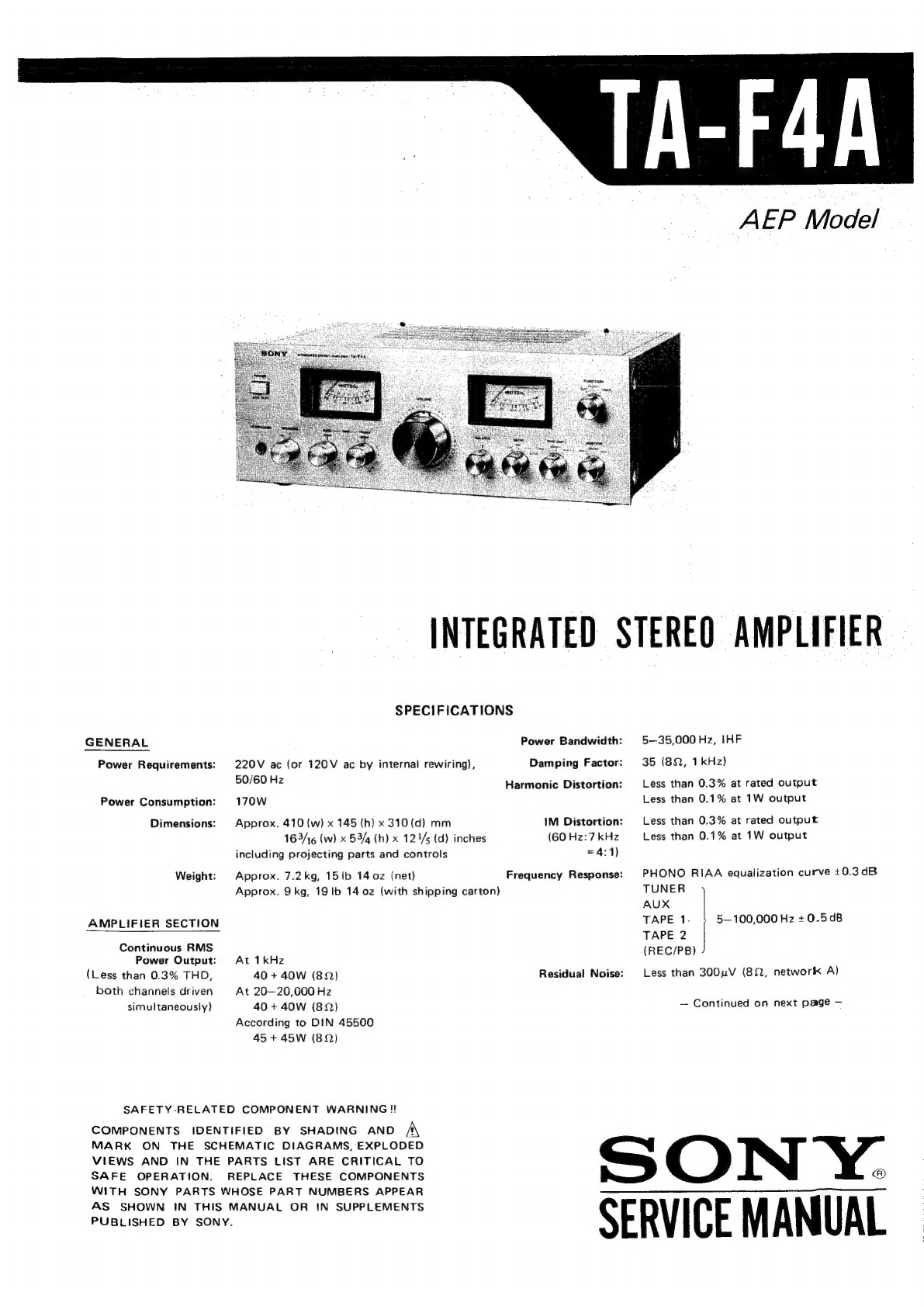
Sony TA-F4A User manual

GENERAL
Power
Requirements:
Power
Consumption:
Dimensions:
Weight:
AMPLIFIER
SECTION
Continuous
RMS
Power
Output:
(Less
than
0.3%
THD,
both
channels
driven
simultaneously)
AEP
Model
INTEGRATED
STEREO
AMPLIFIER
SPECIFICATIONS
220V
ac
(or
120V
ac
by
internal
rewiring),
50/60
Hz
170W
Approx.
410
(w)
x
145
(h)
x
310
(d)
mm
165/16
(w)
x
53/4
(h)
x
12
1/5
(d)
inches
including
projecting
parts
and
controls
Approx.
7.2kg,
15
lb
14
0z
(net)
Approx.
9kg,
19
lb
14
0z
(with
shipping
carton)
At
1kHz
40+
40W
(8)
At
26—20,000
Hz
40
+
40W
(829)
According
to
DIN
45500
45+
45W
(8)
SAFETY-RELATED
COMPONENT
WARNING!!
COMPONENTS
IDENTIFIED
BY
SHADING
AND
A
MARK
ON
THE
SCHEMATIC
DIAGRAMS,
EXPLODED
VIEWS
AND
IN
THE
PARTS
LIST
ARE
CRITICAL
TO
SAFE
OPERATION.
REPLACE
THESE
COMPONENTS
WITH
SONY
PARTS
WHOSE
PART
NUMBERS
APPEAR
AS
SHOWN
IN
THIS
MANUAL
OR
IN
SUPPLEMENTS
PUBLISHED
BY
SONY.
Power
Bandwidth:
Damping
Factor:
Harmonic
Distortion:
IM
Distortion:
(60
Hz:
7
kHz
=
4:1)
Frequency
Response:
Residual
Noise:
5—35,000
Hz,
IHF
35
(82,
1kHz)
Less
than
0.3%
at
rated
output
Less
than
0.1%
at
1W
output
Less
than
0.3%
at
rated
output
Less
than
0.1%
at
1W
output
PHONO
RIAA
equalization
curve
+0.3dB
TUNER
AUX
TAPE
1.
TAPE
2
(REC/PB)
Less
than
300uV
(89,
network
A)
5—100,000
Hz
+
0.50B
—
Continued
on
next
page
—
SON
Y.:
SERVICE
MANUAL

TA-F4A
Inputs:
Maximum
Input
S/N
Sensitivity
|
Impedance
|
Capability
{0.2%
distortion)
(weighting
network,
input
level)
2.5mV
150
mV
80
dB
PH
nee
{-50
dB)
(-14.5dB)
(A,
2.5mV)
TUNER
AUX
TAPE
1
TAPE
2
(REC/PB)
150
mV
(-14.5
dB)
Outputs:
Output
Level
Impedance
150
mV
E
:
REC
OUT
1
(-14.5
dB)
4.7k2
REC/PB
poe
82k2
Accepts
low
and
high
impedance
stereo
headphones
SPEAKER
Accepts
speakers
of
8-162
HEADPHONES
Tone
Controls:
Filters:
BASS
+10dB
at
60
Hz
(turnover
frequency
300
Hz)
TREBLE
+10dB
at
25kHz
(turnover
frequency
5
kHz)
LOW
6dB/oct.
below
15
Hz
HIGH
6dB/oct.
above
9
kHz
0dB=0.775V

1-1.
SERVICING
NOTE
SECTION
1
OUTLINE
When
replacing
a
knob
(
SPEAKERS
/
TREBLE
/
BASS/BALANCE/FILTER/TAPE
COPY/MONITOR/
FUNCTION),
prepare
a
knob
cap
(4-854-266-00)
and
a
knob
mold
(4-854-267-00).
Installation
of
the
knob
is
as
follows.
SPEAKERS
TN
@
Coincide
a
slit
with
a
mark.
Knob
Mark
Position
Y
i)
TAPE
COPY
li
MONITOR
slit
FUNCTION
0
Turn.
knob
mold
1-2.
BLOCK
DIAGRAM
Sate.
S$2-1
FUNCTION]
[MONITOR
TUNER
J101
£Q
AMP
PHONO
PHOWO
Qlol~
103
J102
Tua]
©
4103
ag
|e
s3
[TAPE
COPY
rare
7
@
“o
TAPE
1-2
31-1
SOURCE
OTAPE
2~1
©
TAPE
1
+2
105
REC
OUT
1]
O-
o=hO
TAPE
21
CNJ4
$3-2-|
TAPE
2
CREC/PB)
SOURCE
BALANCE
R-CH
@
R-CH
IS
OMITTED
TAPE
1
RV
201
RV1
VOLUME
}
OTAFE
2
ORIVE
AMP,
B+
RIPPLE
EQ
AMP,
,
FILTER
Be
ato4
DRIVE
AMP,
B-
RIPPLE
EO
AME,
FILTER
B=
Q105
POWER
AMP
Q201
DRIVE
AMP
1¢
204
POWER
AMP
Q202
TA-F4A
—@
If
necessary,
widen
the
slit.
@
Coincide
@
with
the
mark
and
install
the
knob
cap.
knob
cap
Part
No.
Description
X-4854-213-1
Knob
Ass’y
including;
4-854-266-00
Cap,
knob
4-854-267-00
Mold,
knob
s5
POWER
AMP,
B+
POWER
AMP,
SPEAKERS
TM
101
°
[SPEAKER
A
TM
102
8
SPEAKER
B
3401
ey
fo]
HEADPHONES
$6
3
EH)
TA-F4A
SECTION
2
DISASSEMBLY
Note:
Follow
the
disassembly
procedure
in
the
numerical
order
given.
CASE
AND
BOTTOM
COVER
REMOVAL
Case:
@
to
O
The
component
side
of
the
speaker
board
and!
main
amp
board
can
be
checked.
Both
side
of
the
EQ
amp
board
can
be
checked.
Bottom
Cover:
@
to
@
The
conductor
side
of
the
main
amp
board
can
be
checked.
@
screw,
©
BW4x12
©
BVTT
3x6
screw,
©)
BW
4x12
@
BVTT
3x6
FRONT
PANEL
REMOVAL
The
POWER
switch,
meters
and
variable
resistors
can
be
replaced,
after
removing
the
front
panel.
METER
LAMP
REPLACEMENT
Note:
To
obtain
the
same
brightness
of
meter
lamps,
replace
both
lamps
(L-CH
and
R-CH)
together
with
new
ones.
C1)
adhesive
tape
(transparent)
C3)
knobs
(with
2mm
L-shaped
hexagona/
wrench)
@
1-518-309-00
meter
lamp
e
BVTT
3x6
meter
cover

TA-F4A
TA-F4A
|
slit.
nark
my
INES
SECTION
2
DISASSEMBLY
Note:
Follow
the
disassembly
procedure
in
the
numerical
order
given.
CASE
AND
BOTTOM
COVER
REMOVAL
Case:
@
to
@
The
component
side
of
the
speaker
board
and!
main
amp
board
can
be
checked.
Both
side
of
the
EQ
amp
board
can
be
checked.
Bottom
Cover:
@
to
@
The
conductor
side
of
the
main
amp
board
can
be
checked.
@
screw,
@©
BW4x12
OQ
BVTT
3x6
FRONT
PANEL
REMOVAL
The
POWER
switch,
meters
and
variable
resistors
can
be
replaced,
after
removing
the
front
panel.
knobs
(with
2mm
L-shaped
hexagonal
wrench)
@
BVTT
3x6
METER
LAMP
REPLACEMENT
Note:
To
obtain
the
same
brightness
of
meter
lamps,
replace
both
lamps
(L-CH
and
R-CH)
together
with
new
ones.
@
adhesive
tape
(transparent)
meter
cover
@
1-578-309-00
meter
lamp
SECTION
3
ADJUSTMENT
|
TA-F4A
DC
Bias
Adjustment
Note:
1.
Perform
adjustments
a
few
minutes
passed
after
POWER
switch
turned
ON.
2.
With
no
signal
input.
Adjust
RT201
for
11
mV
dc
reading
on
VOM.
RT201
(L-CH)
Meter
Level
Adjustment
Setting:
VOLUME
control:
maximum
Procedure:
l.
af
osc
oo
attenuator
100k2
82
(1W)
page)
oO
i
e)
O—O
O
Ne
scoot
=
Fiz
te
ea
teasl
SPEAKER
Adjust
attenuator
for
2.83V
(1
W)
reading
on
VTVM.
Adjust
RT401
(L-CH)
and
RT451
(R-CH)
so
that
meters
indicate
1
W.
Adjust
RT251
for
11
mV
dc
reading
on
VOM.
RT251
(R-CH)

TA-F4A
SECTION
4
4-1.
MOUNTING
DIAGRAM
DIAGRAMS
_
C
VOLTAGE
SELECTOR
BOARD
(COMPONENT
SIDE
)
CINPUT
BOARD}
(CONDUCTOR
SIDE)
(GRN)
Ic201,
1C251
BLOCK
DIAGRAM
Yt
CURRENT
MILLER
OF
bern
DIFFERENTIAL
BIAS
at
AMP
2
CIRCUIT
B-CLASS
DRIVE
AMP
Ji52
«J
153
a,
WHT
|WHT
{feo
AG:
FF
CHASS!S
GROUND
[C
MAIN
AMP
BOARD
J
(CONDUCTOR
SIDE)
0251
9202
;
R218.
Ik
ard
feo
eS
y
oe
22cm
oo
Ge
HO
’
ae
ay
40
Vs.
Nace
F
oe
R220
: Z |
:
0.22(
2W)
{EQ
AMP
BOARD
J
(CONDUCTOR
SIDE)
JAPAN
DC
BIAS
CHECK
Cat
ms
Ls
<
==)
(0.01/500V
=
-40V
RIG2
33k
x
C160
-47/16V.
€264°-47/10V-
OO
ve
gerne
"0259
palo
©
Senn
C266
'§
tov
J
nN
n
ar
DB
DN
4
IN
=O
c209
C210"
259°
6.012
|
750p
0.012
R229
330
BALANCE
101
ia
a
at
aia
252
251
209
208
202
201
105
1€251
1C201
207
102,103
104
152,
153
253
203-206
204
205
264.
262
26!
263
206
207
214-212
21
213
203,
201
2
259
260
210
209
205
208
202,
204

(GRN)
1C201,
1C25!
DIFFERENT!
AMP
|
BLOCK
DIAGRAM
CURRENT
MILLER
DIFFERENTIAL
AMP
2
B-CLASS
DRIVE
AMP
BIAS
CIRCUIT
C
VOLTAGE
SELECTOR
BOARD)
(COMPONENT
SIDE
)
B-CLASS
DRIVE
AMP
C
MAIN
AMP
BOARD
(CONDUCTOR
SIDE)
RVI
100KA)
2V203
100k
aA
AE
|
im
1C251
252
C201
251
209
208
202,
20
253203
206
204
205
BONS
»
2206
261
263
206 207
214212
Zul
213
203,
201
se
259
260
210
209
205
208
202,
204
ARR
tk
(SPECIAL)
ad
a
LL
POWER]
ON
OFF
CHASSIS
GROUND
Note:
O—:
parts
extracted
from
the
component
side.
@—:
parts
extracted
from
the
conductor
side.
™:
part
mounted
on
the
conductor
side.
:
B+
pattern
Signal
Path
oe
ee
|
LCH
meee
me
op
>
R-CH
meee
©
L-CH
or
R-CH
Color
code
of
sleeving
over
the
end
of
the
jacket.
fn
J401
[HEADPHONES]
ES
[i2]
401
402
451
452

4-2.
SCHEMATIC
DIAGRAM
Jil
CINPUT
BOARD]
104
|
ee
J05
aa
REC
OUT]
ROP
BOK
CNJ!
TAPE
2
REC/PB
QIOl
28C2129
EQ
AMP
CEQ
AMP
BOARD
]
Ql02
2SA872
=
Q103._
2SCi632
AMP
23V_EMITTER
FOLLOWER
$2
MONITOR
TAPE
2
CMAIN
AMP
BOARD
}
SOURCE
TAPE
|
S2-]
Reve
ie
BALANCE
+
C202
0,22
om
$3
TAPE
COPY
TAPE
2>1
SOURCE
{
TAPE
|+2|
lis)
REC
OUT!
a
R-CH
Jt5I
QISI_
2sc2i29
EQ
AMP
RIS)
cist
W
RIS3
aes
bo152
oy
20V
QI5I
t)
~06V
$
C153
RIS4.
C160
QH2
2SA872_
QIS3._2SCI632
AMP
23V
Ciba
RIG
si
20.6V
ise
a
Kc)
0153
(je
css
|
Ss
L6V"L_ayy
RIGO
RIS?
RIS
C156
CIS?
RI5g
H
SRi6l
RIGS:
EMITTER
FOLLOWER
$3
[TAPE
COPY
TAPE2—>
|
SOURCE
TAPEI—=
2
n
Ny
MONITOR
R252
——J
R254
[BALANCE]
C252
$4-2-2
iN
S4[FILTER
LOW
‘
R
104
J
(M)
RVI
100k(A)
(C201
CXI7]
=O2I3
MVIZN_
Dil
IS2076A
D214
M
DRIVE
AMP
C1986
Q203,204,206,
207
2:
AMP
PROTECTOR
wens
A
RV2
(A)
Ri
100K
{C253
OV,
[Ic
b
DIFFERENTIAL
AMP
2
DIFFERENT
AMP
VAL
|
CURRENT
=
BIAS
CIRCUIT
VI2N
=
-D2I2
IS2076A
=
Q201
2SA77I
=
Q202
25!
POWER
AMP
POWER
40
OC
BIAS
CHECK
POINT
0208
MV203V
—
2
(SPEAKER
BonRD
1
[ETE
SCE34A,,
gy
0205
25K678
.
y
PROTECTOR
[S401
Bags
ay
RIM!
22
=
||!
=
0207
ISIS555
CHASSIS
GROUND
osqy
C251
CXI71
==
.D263.
MVI2N
DRIVE
AMP
(3)
R256
K
|
J
oerenentiat
=
ANP
|
7
REG
CURRENT
Red
©
4
|
|
ot
faal
R255:
@)
7251
47k
DC
BIAS
C2u,
0.2
(
RV203
100k
0209
ISI555
D210
1T22A
R230
47k
SPECIAL}
D261
IS2076A
D264
MVIZ2N
=:
262
IS2076A
=
Q25I
2SA77I
POWER
AMP
40v
25!
role
tae
|
R270
c2i9
55
O/ev
~234V
100k
(SPECIAL)
C259
0259
ISI555
D260
IT22A
Q252
2SCI986
Q253
2SC634A
POWER
AMP
PROTECTOR
Cie
100
25V
ft
C3
}
105
2SA678
RIPPLE
FILTER
av
0205
0206
24v
R310
22k
|
lo
7
SO
A\
Av
C304
4
25v
D201~204
SIBOI-B
RECT
2.2/50V
jk
(aw)
040!
I)
R402
1.5k
wew)
S6-1
L401
,22uH
4
rq
i
a
$5
[SPEAKERE
R401
A
LOUW/ew)
;
OFF
t
B
I]
$5-2
L451
fs
O-O
im
—,
R451
|
a
R455
eee
R405
RAL
Cassee
“470
W2W)
403.
$R454
0033
Iles
~
METER
LEVEL
cas! pagg nasi
RUS
R452
D215
SIBO-B
0205,206
EQAOI-25
|
\
POWER
(308
(0.01/500V)
x2
ame
a
0203
0201
0204
020:
coo!
0.047/300

/OLUME
RVI
100k
(A)
D213
MVI2N
——D2II
IS2076A
D214
MvI2!
R205
7
C218
al
ASS
OUN!
C201
CXI71
VEL
23.4V
DRIVE
AMP
a0v
i
it
fo
Inia
0401
R208
gl
A
,
j
I
Nr22offe]]
©
%
oc
Bias
om
i
cuaO
Da
tee
D208
MV203V
0207
1SI555
+
Q
Nor
Rage
1M
3a4y
me
390V
wew)
6206
02
tO)
Gar
palt
AV
ee
BPA
i
R22
$5-1
mo
L-CH
™
or
150
L401
1.22uH
fs
0
B.5V
lesa
aN
sRele
Rees
1
<=
0
it
O—
27k
cas
0,0033
H
$5
SPEAKER
A
x
ae
=
0209
ISI555
49,
a
6:
;
“Tr
"as
eh
D210
IT22A
oF
O7—-
[eet
H+
)
Mi
oon
I
s5-2
B-
CLASS
nas
A\
i
Last
TMI02
DRIVE
AMP
5
Bl
2
aR
bee
ae
RY201
|
To]
|
3
\
L
R303
LZ]
$15
|u
2
228
re
pee
RAS
|
es
SPEMER
>
O
4
"
Hi
13V
|
74
aaa
fi
C204
R306}
!
O—+0
—+
C2i2
1.
470
R304
33/25V
0018
pele
30-476
lov
0208
22k
(2W)
R455
f
i
Gaur
1
ay
AS
0204
ze
G30e
ie
0207
Ja
oy
'
ait
ae
41
ie
‘0214
301
V
0453
470
a
(yr
220
OV
)
i)
Be
1)
mn
A)
+
ln
(W2W)
iq)
ae
R50
cag3
R454
|
40
~384V
yt
100/104
io
DOS
t-&AV[]
(HEADPHONES)
C219
METER
oes
Al
R209
Rete
8
2
pee
LEVEL
a
A
C45
pag
vast
RTOSL
1S
SS
7
p
-234V
Rabe
|
eeereen
ver
os
D215
SIBOI-B
osay
IC251
CXI7L
D263
MVIZN
—D26I
IS2ZO76A
0264
MVIZN
262
IS2076A
Q251
2SA77\
fm
+
a
“DRIVE
AMP
;
POWER
AMP
EAN
1
@o
aor
AL
F202
R267
4ov
R270
al
AP
oc
Bias
18
1A
0251
F
|
©
of
CHECK
POINT
:
(y\>39v
0263!
S8AV
me
C)
0261
8%
ov
B—CLASS
R263
A\
DRIVE
AMP
~8iV
RT
my
Oe
Axrzsi
FF]
D259
1SI555
DC
BIAS
re
R264
D260
IT22A
AW
=
T
(264,
C260
R281
(254
R280
cage
R275
base
ov
GF
reap
78
R265
>
avose
sk
R279
R276
Rv253
1
0253
Cas
100k
C261
1,-,(00K
ay
10264
0252
(v5
*
(SPECIAL)
(SPECIAL)
a
ov
qd)
13V
ini
gee!
@
(266
6259
ROWSE
ROTA
agi
NS
il
Q252
2SCI9B6
POWER
AMP
Q253
2SC634A
PROTECTOR
TER|
~
-
|
|
KSPEAKER
BOARD
}
[ME
N
=
D212
IS2076A
—Q201
2SA771
—Q202
2SC1986
Q203,204,206,207
2SC634A.,,
.,,
Q205
2SA678
ie
ue
POWER
AMP
POWER
AMP
PROTECTOR
:
PROTECTOR
C401
R403
RT401
2.2k
Cil2
100
us
25V
C3
47
25v
it
cil4
47
is)
20
RIIZ.
{
EQ
JAMP
BOARD
}
0206
305
4
25v
2ay
em
lA
Rau
24)
Aik
S
209
I
QI05
2SA678
RIPPLE
FILTER
~40V
0205,206
EQAOI-25
308
(0.01/500V)
x2
oP
‘
ae
>
0263
020i
0204,
0204
uH_~+_
C309
(0.01/500V)x2
!
}-
23.4V
Q209
2SA678
=
D201~204_
SIBOI-B
REG
RECT
4
=
y)
mus)
40V
=
x
S
ole)
RED
F201
SISA
cool
0.047/300V
E
VOLTAGE
SELECTOR
BOARD
BRN
0
OFF
N
CNP2
~AC
II
TA-F4A
ote:
The
components
identified
by
shading
and
/\
mark
are
critical
for
safety.
Replace
only
with
part
number
specified.
Note:
@
Components
for
right
channel
have
same
values
as
for
left
channel.
e
All
capacitors
are
in
uF
unless
otherwise
noted.
pF
=
nuk
SOWV
or
less
are
not
indicated
except
for
electrolytics.
e
All
resistors
are
in
ohms,
%W
unless
otherwise
noted.
kQ
=
10002,
MQ
=
1000
kQ
e
All
adjustable
resistors
have
characteristic
curve
B,
unless
otherwise
noted.
e
-f4}
:
nonflammable
resistor.
©
ome:
B+
bus.
e
:
panel
designation.
e
((__)
:
adjustment
for
repair.
©
meme:
B-
bus.
@
Voltages
are
dc
with
respect
to
ground
unless
otherwise
noted.
@
Readings
are
taken
under
no
signal
conditions
with
a
VOM
(20k2/V).
e@
Voltage
variations
may
be
noted
due
to
normal
produc-
tion
tolerances.
e
Switch
Position
Switch
PHONO
SOURCE
SOURCE
FUNCTION
MONITOR
TAPE
COPY
FILTER
OFF
SPEAKERS
A
POWER
OFF
D201—204
oe
\:
U05G
(S1B01-B)
cathode
cathode
D207,
209
\:
~
D259
:
a
D210,
260
“
DW.
D401,
451
\
ano
aa
D402,
452
D211,
261
\
D212,
262
D205
none
t
EQB01-25
(EQA01-25)
cathode
lq
og
a,
-
‘andile
anode
Replacement
Semiconductors
For
replacement,
use
semiconductors
except
in(
—).
0101,151:
2SC2129
Q103,153:
2SC632A
(2SC1632)
a104:
2SC634A
(2SC1634)
203,
204
).
Goo
907
‘
2SC634A
:
:
al
E
Fe
%s
Q102,152:
2SA705-8
(2SA872)
c c
6)
©)
E E
Fc
E—E
CB
0105,
205).
cons
ie
2SA678
Cc
)
E
E
cy
Q201,
251:
2SA771
c
HEL.
E
ac
F
Q202,
252:
2SC1986C
(2SC1986)
1C201,251:
CX171
14131211109
8
1234567
{Top
view)
D208:
MV203V
K
1S1555
anode
cathode
1722AM
(1722)
Ls
E
1S2076A
D213,
263
)
.
ay
Bod.
Seah
MV12N
.
cathode
{~
anode

TA-F4A
|
4-3.
MOUNTING
DIAGRAM
—
Speaker
Board
—
—
Conductor
Side
—
METER
LEVEL
:
(Ligs
R402.
1.5k
(1/2W),
ie
smart
AA
anensmennn
cated
“Jcaog
Tzz/iev
©.
2:2
[30d
:
R403
Hk
(I72wy
oe
,
9401
C451
F
—
R453.
1k
(1/2W)
ee
|
eh
OA
i
2.2/50V.
PR)
-
—@.
om
ce
tf
©
R452
15k
(1/2)
0451...
8
Weare
CO
ok
Om
. .
04520
ae
nf
ea
Oe
Oe
RT4SE
CB
fe
RASA
eee
22k
casa
|
‘(BLK
=
S
METER]:
22716V
LEVEL
(Rs
L451
L.22yH
Q
wz
o
R451.
10.172)
ow
mt
(so
i
Zz
SH
L401
L22pH
|
R404
10(1/2W)
J401
|
HEADPHONES

|
TA-F4A
SECTION
5
EXPLODED
VIEWS
wOnN0g
‘420027
ASS
}004
VW)
O109-ES9E-X
uoneniyioeds
‘jage7
®
00926-0986
ase
D
00-€2E-vS8-r
gouy
“pIoW
7ouy
“deo
Assisiood
@
00297
58
OD
00-99C
PS3->
@
o10sessex
OXE
LIAB
t
9XELLAG
~
NOLLINAS
‘HOLINONY
a
‘AdOD
FdVL
“JON
IVE
‘FIGIUL
Sw
“Sua
vads
‘A58y
Gouy
eee
Q
bererserx
77
ASS?
GOUY
FNATIOA
Gm
paydans
a,
FWNIOA
‘Assy
gouy
Q)
O60e-rSer-X
—
A
XN
>
_-gouy
“pow
Y
00-292
698-7
quoi
“ASS
faued
@
1-20E-7580-x
GXELLING
Y3MOd
“Assy
qouy
@
0209
e59-x
h
9XELLAG
S
a
uonnes
punoib
‘jaqe]
7
y
©
10196-40Le
|’
ee
aseo
‘uorysng
@
0079-8re-r
‘Ajuo
sjapow
ueadosng
‘
peay
paz20s
=
(—)
*‘pajou
asimsayyo
ssajun
‘QDIAJBS
BUIINOI
40}
PasINbas
wopyas
aue
Aayl
asnedsaq
paxd01s
Jou
aie
UOoldisosap
uORNe?
uleul
‘jaqey
@Q
v00cs-0cer
(1)
qouy
‘dep
QD
o0099t-vs8b
0}
afgeoijdde
ase
(Qo
@))
$1913]
Pajig
©
adAj
(sSada4
ssosd)
Sdijjiyq
ase
Smads
|i¥
e@
ou
JOo/pue
sequinu
qed
ou
YM
suai)
©
@
Ievoeore
Zi
xp
Ma
@
‘Me0$
110K
13

TA-F4A
“Ajuo
sjapow
ueadosng
0}
ajqeaijdde
ae
(Qo
@))
$492]3)
Pajdig
e
peay
paiiojs
=
(—)
“palou
asimiay
io
ssajun
adA}
(sSadai
Ssold)
sdijjiyg
aie
SMai2S
|i¥
e
‘BDAIBS
BUIINO!
40}
PasINbas
Woptas
aie
Aay}
asnedaq
pax901s
Jou
ase
uoldiuosap
Ou
JO/pue
yaquinu
qed
ou
YUM
sia}
e
Ta10N
(1S)
NOILINAY
fapys
Ale1Os
“YOM
QD
OOSLEecsot
pseog
dwe
OF
‘4sapjoy
“paijioads
daquinu
jied
upim
Aju
adejday
*Ajayes
104
JeONV1I9
ae
yew
\7
pue
Buipeys
Aq
paynuap!
sjuauodwos
ay]
:3}0Kj
{19%
‘L0@A¥)
FONVIVE
‘i
Jaigeisen
(W/N}
054001
40381894
ee
NONE
@
00912-9221
D
209181166
(
awe7\
“
\oo-606-815-1]
.
(2
LFW)
due
Buipnjour
“ajay
:
#8)
GRELIAG
©
o00ze0rs-1
YIL
UA
“Opys
Aseros
“YyouUMS
QD
Ovezsgt
403SISAL
BfQRIseA
40
Y2UMS
YIM
payddns
9XELIAE
Op
>
(€
‘@S)
AdOD
FdVL
“YOLINOW
“epl{s
Asel01
“YRIMS
@
00€e7sot
4OISISBs
B}GRIIEA
40
YOUMS
YLIM
payddng
dajaus
‘vorysng
Q
Z2OGIF
1166
yoet
yum
payddns
mm
©)
G9XELLIAG
asny
“sapjoH
@
O0-1E1-€8S-1
>|
v
9XELIAGB
|
Se
jaued-gng
{€S2
“EOZAY)
SSVE
vajgerien
(je1oads)
UHOOL
‘sOISISAY
@
OO1Z-9ee1°
(ZOZ4)
Wi
“ang
@Y
00-8L0-CES4
V
.
@
00-L€z-zES-1
(SS)
SYIANVIdS
‘Ops
AseIOs
“YIM
BP
00zLELSS!
(9S)
BIMOd
Juaqngysnd
*Y93Mg
(Z
‘1LA#)
IWNTOA
@
£4-90%-755-1
Jayqenen
(v7)
UWAOOL
“s0IsIs8Y
Vv
@
00°106-92e-1
(10r)
SINOHAQGVIH
“esneurg
“yer
|
@
00195-2051
4ayeads
“pseog
yNnI4#9
ajajCuioD
(25€
“ZOZAS)
F18FGL
fayqeuen
(yei2ads)
%3¥4OO1
“s01SISAY
OXGLLAB
i
{Li}
4emod
‘sautsoysuest
G
OOEIZ-
IEE
©
16-190°9¢01
¥
(2)
OXPLIAG
14


TA-F4A
‘Ajuo
sjapow
ueadoing
0}
ajqesijdde
aie
(Qo
@®)
$181}3]
P3|du1D
e
peay
parios
=
(-)
“pajou
asimiayyo
ssajun
adAy
(s8a984
SS049)
sdiyjiyg
ase
SMa1DS
||Y
©
"QDIAUBS
BUIINO
410}
PasiNbal
wWopyes
a1e
Aayy
asnesaq
pax90is
}OU
ase
UONd419sap
ou
40/pue
saquinu
qed
ou
YUM
sual]
@
:a]0N
Joquinu
yied
ipim
Ajuo
asejday
“Ajayes
40}
jeoij149
ase
spew
\/
pue
Builpeys
Aq
palynuep!
syuaUOdWwoOd
ay]
:220;y
OXELLAG
sisseYD
(1
fNQ)
lz
FdVL)
8d/IFH
‘10290U09
@
00-6bS-605"!
a
andu
‘pseog
NIH?
aaduioD
pseog
s0,Jajas
abexjOA
*sapjOH
(994
“S01
“6S!
‘vOIT)
140
D39Y
‘t
3dV1
Op
‘ouoyd
“yoer
@
'eherLogt
jeune
punosB
‘jage7
OXE
LING
®
00-60L-81rE
(€G4-451
‘€01—L087)
XAV
“YINAL
‘ONOHd
09
‘ouoyd
‘yer
©
xXx-0€¢-20¢-+
dojemsur
‘buiysng
GY
00-S84-€0LE
(7)
yurs
1eaH
40399188
@6e1j0A
‘pieog
nag
aajduog
@
Vsttveerv
9XELLAG
ase
“Vaary
DY
OO-vEL
Leb
sozeynsul
“1aausS
@
OOslEerser
jeuiusa
punos6
‘422805
@)
00-€66-10LE
punosG
“peuiusa
f
@
00S91-90LE
ayseyd
“JOALY
@D
O0-vEL
7189
it
yujs
yeay
‘(2/6))
42D/OH
9X€
LLANE
yuls
128
9*E
LLANE
{ZdNI)
Ni
OW
~
“dE
‘soIsauUAD
dear
"jaued
®
yor
BXEAG
‘VL
QD
00-028-7S8-7
(g)
4uis
1838H
(ZOL
“LOLWL)
a
YINWIS
‘AS
jeurusas
Q
00-25
9ESt

TA-F4A
SECTION
6
Note:
Circled
letters
(@
to
(Z))
are
applicable
to
ELECTRICAL
PARTS
LIST
—_£¥"oP#2"
models
ony.
Ref.
No.
Part
No.
Description
Ref.
No.
Part
No.
Description
COMPLETE
CIRCUIT
BOARD
CAPACITORS
A\A-4394-115-A
©
Voltage
Selector
All
capacitors
are
in
uF
and
electrolytic
unless
otherwise
noted.
:
SOWV
or
less
are
not
indicated
except
for
SEMICONDUCTORS
electrolytics.
p=
uF
cool
A\1-108-749-12
0.047.
300V.
mylar
,
Transistors
C101,151
—-1-121-651-11
@
10
16V
C102,152
—-1-102-903-11
@)
100p
ceramic
Qi01,151
®
28c2129
C103,153
—-1-121-938-11
@)
470
10V
=>
Q102,152
©
28A705-8
C104,154
~—-:1-121-414-11
®
100
10V
=>
Q103,153
®
28C632A
C105,155
1-102-971-11
@
82p
ceramic
=>
Q104
2SC634A
QL05
©
28A678
C106,156
—-1-108-359-12
@
0.027
mylar
C107,157
—-:1-108-576-12
@)
0.0075
mylar
:
Q201,251
©
28a771
C108,158
=:
1-123-232-11
@)
4.7
25V
(nonpolarized)
=>
Q202,252
©
28c1986c
C109,159
—-1-108-227-12
@
0.001
mylar
Q203,204
2SC634A
C110,160
~=—-:1-121-409-11
@
47°
16V
Q205
©
2SA678
Q206—208
2SC634A
C111,112
—-1-121-935-11
®)
100
25V
Q209
©
28A678
C113,114
~—-1-121-410-11
®
47
25V
ICs
C201,251
—-1-108-232-12
@)
0.0033
mylar
C202,252
—
1-108-254-12
0.22
my
lar
1C201,251
@®
cxi71
C203,253
—-1-121-391-11
@
1
50V
204,254
=—-1-121-392-11
@
3.3
25V
Diodes
C205,255
—-1-102-971-11
@
100p
ceramic
=>
D201—204
U05G
C206,256
=>
D205,206
EQBO1-25
C207,257
pee
ee)
oa
D207
181555
C208,258
—
1-108-244-12
@)
0.033
mylar
D208
MV203V
C209,259
—-1-108-357-12
@)
0.012
my
lar
D209,259
181555
C210,260
—-1-104-074-11
@)
750p
polystyrol
=>
D210,260
(@)
1T22AM
C211,261
—‘1-108-605-12
@)
0.12
my
lar
D211,261
io7bh
C212,262
—-:1-108-358-12
@)
0.018
my
lar
D212,262
C213,263
—-:1-108-239-12
@)
0.01
my
lar
D213,263
aia
C214,264
—1-121-409-11
@)
47
10V
D214,264
C215,265
—1-108-232-12
@)
0.0033
my
lar
=>
D215
U05SG
C216,266
=-1-121-414-11
@)
100
10V
=>
p401,451
C217,267
ae
(@)
1T22AM
sig
2
Melee
@
47
10V
C219
1-121-651-11
@
10
16V
:
C301
1-121-981-11
220
6.3V
C302,303
~—-1-121-414-11
@
100
10V
e@
=:
Due
to
standardization,
interchangeable
replacements
may
be
substituted
for
parts
specified
in
the
diagrams.
Note:
The
components
identified
by
shading
and
A,
mark
are
critical
for
safety.
Replace
only
with
part
number

Ref.
No.
Part
No.
Description
C304,305
—-1-121-410-11
@
47
25V
€306,307
A\
1-125-157-11.
©)
6800
42V.
C308,309
—-:1-102-355-11
0.01+0.01
500V
ceramic
C401,451
—-:1-121-450-11
@)
2.2
50V
C402,452
=
1-121-479-11
(@)
22
16V
C403,453
1-108-244-12
(A)
0.033
mylar
RESISTORS
All
resistors
are
in
ohms.
Common
%W
carbon
resistors
are
omitted.
Refer
to
the
list
on
page
19
for
their
parts
numbers.
Check
schematic
diagram
for
values.
k=
1000
R208,258
A.
4.7K
%W
carbon
1-211-559-11
;
R209,259
A\
©
(nonflammable)
R210,260.
A\
100
%W_
carbon
os
1:211-522-11
oe
.
R21
126
A
®
(nonflammable)
R213,263
A\
1-211-502-11
15
%W.
carbon
wae
ne
hth
:
(nonflammable)
R216,266
A
1-211-526-11.
©
150
%W~
carbon
none
‘s
;
(nonflammable)
R219,269
0.22
2W.
wirewound
Eee
ym
1-217-151-11
R220,270
A\
(nonflammable)
R306.
AA
1-206-656-11
(A)
470
2W
metal
oxide
(nonflammable)
R308
A\1-211-498-11
@
10
%W
carbon
(nonflammable)
R309,312
A\
1-211-524-11.
@
120
%W.
carbon
(nonflammable)
R401,451
—1-212-372-11
@
10
%W
carbon
R402,452
—-1-213-145-11
1.5k
%W~
carbon
R403,453
—-1-213-143-11
1k
%W
carbon
R404,454
—
1-212-372-11.
@
10
%W
carbon
R405,455
—
1-213-139-11
@
470
%W
carbon
RT201,251
1-224-186-31
47k
(B),
adjustable;
DC
bias
RT401,451
1-224-250-XX
©
2.2k
(B),
adjustable;
meter
level
RV1,2
1-226-201-00
()
100k
(A),
variable;
VOLUME
RV201,251
1-226-215-00
©
100k
(N/M),
variable;
BALANCE
TA-F4A
Note:
Circled
letters
(@
to
@)
are
applicable
to
European
models
only.
Ref.
No.
Part
No.
Description
RV202,252
1-226-213-00
O
100k
(special),
variable,
TREBLE
RV203,253
1-226-214-00
©
100k
(special),
variable;
BASS
SWITCHES
$1
1-552-375-00
(©)
Rotary
Slide,
FUNCTION
$2,3
1-552-373-00
©)
Rotary
Slide,
MONITOR,
TAPE
COPY
S4
1-552-374-00
(©
Rotary
Slide,
FILTER
$5
1-552-372-00
(©)
Rotary
Slide,
SPEAKERS
S6
A\..
1-552-206-11.
©
Pushbutton,
POWER
JACKS
J101-103
1-507-430-XX
(©)
Phono,
6p;
PHONO, TUNER,
AUX
J151-153
iD)
Phonoj
ep
J104,154
:
-507-433-2
:
1105,155)
1-507-433-21
©
Phono,
4p;
TAPE
1,
REC
OUT
1
J401
1-507-56
1-00
Binaural,
HEADPHONES
MISCELLANEOUS
CNJ1
1-509-549-00
Connector,
REC/PB
(TAPE2)
CNP2
A\~
1-509-546-00.
©
Connector,
3p;
AC
IN
F201
A\_
1-532-237-00
@)
Fuse,
3.15A
F202
AA
1-532-078-00
@
Fuse,
1A
~
ME1,2
1-520-320-00
()
Meter,
including
lamp
RY
201
1-515-302-00
()
Relay
Tl
A
1-446-051-11
©
Transformer,
power
TM101,102
1-536-524-00
©)
Terminal
Strip,
SPEAKER
A,
B
1-518-309-00
Lamp,
included
meter
A
1-533-131-00
@)
Holder,
fuse
e
components
identified
by
shading
and
/\
mark
are
critical
for
safety.
Replace
only
with
pat
n
umber
specified.
1
|

TA-F4A
Note:
Circied
letters
(®
to
@)
are
applicable
to
European
models
only.
ACCESSORIES
&
PACKING
MATERIALS
Part
No.
3-701-020-00
3-770-455-11
4-853-916-00
4-854-329-00
4-891-037-00
Description
(A)
Bag,
plastic;
instruction
manual
(©
Manual,
instruction
Cushion
©
Carton
Bag,
plastic;
unit

TA-F4A
Note:
Circled
letter
@
is
applicable
to
European
model
only.
1/4
WATT
CARBON
RESISTORS
)
Q
Part
No.
Q
Part
No.
Q Part
No.
|
2
|
PartNo.
|
Q
1-244-601-11
|
10
|
1-244-625-11]
100
|
1-244-649-11
|
1.0k
een
10k
|
1-244-697-1311
|
100k
|
1-244-721-11
i
.OM|
1-244-745-11
-1Mj
1-244~-746-11
.2M|
1-244-747-11
.3Mj
1-244-748-11
.5M}
1-244-749-11
1-244-602-11
|
11
|
1-244-626-12
|
120
|
1-244-650-1]
|
1.1k|
1-244-674-11
|
12k
|
1-244-698-11
|
110k
|
1-244-722-11
1-244-603-11
|
12
|
1-244-627-11})
120
|
1-244-651-11
|
1.2k|
1-244-675-11
|
12k
|
1-244-699-11
|
120k
|
1-244-723-11
1-244-604-11]
13
|
1-244-628-11]}
130
|
1-244-652-11
|
1.3k|
1-244-676-11
|
13k
|
1-244-700-11
|
130k
|
1-244-724-11
1-244-605-11
1-244-629-11
1-244-653-11}1.5k|
1-244-677-11
}
15k
|
1-244-701-11]
150k
|
1-244-725-11
=
ee
aw
oo
=
ttt
1.6
|
1-244-606-11
1-244-630-11
1-244-654-11
|
1.6k|
1-244-678-11
|
16k
|
1-244-702-1)
|
160k
|
1-244-726-11|1.6M|
1-244-750-11
1.8
|
1-244-607-11]}
18
|
1-244-631-11]
180
|
1-244-655-11
1-244-679-11
|
18k
|
1-244-703-11
|
180k
|
1-244-737-11
|1.8M,
1-244-751-11
2.0
|
1-244-608-21
||
20
|
1-244-632-11
|
200
|
1-244-656-11]
2.0k)
1-244-680-11})
20k
|
1-244-704-11
|
200k
1-244-728-11],2.0M|
1-244-752-11
9.2
|
1-244-609-11
|
22
|
1-244-633-11
|
220
|
1-244-657-11
|
2.2k|
1-244-681-11
|
22k
|
1-244-705-11
|
220k
|
1-244-729-11
2.2M)
1-244-753-11
2.4
|
1-244-610-11]
24
|
1-244-634-11]
240
|
1-244-658-11
|
2.4K)
1-244-682-11
24k
|
1-244-706-11
|
240k
|
1-244-730-11
|
2.4M|
1-244-754-11
2.7
|
1-244-611-11
])
27
|
1-244-635-11
}
270
|
1-244-659-11
|
2.7k|
1-244-683-11
|
27k
|
1-244-707-11
|
270k
|
1-244-731-11]}2.7My
1-244-755-11
3.0
|
1-244-612-11
]
30
|
1-244-636-11
|
300
|
1-244-660-12
|
3.0k|
1-244-684-11
|
30k
|
1-244-708-11
300k
|
1-244-732-1113.0M|
1-244-756-11
3.3
|
1-244-613-11
|
33
|
1-244-637-11]
330
|
1-244-661-11|
3.3k|
1-244-685-11
|
33k
|
1-244-709-11
|
330k!
1-244-733-11
|3.3M)
1-244-757-11
3.6
|
1-244-614-11
|
36
|
1-244-638-11]
360
|
1-244-662-11
|
3.6k}
1-244-686-11
36k
|
1-244-710-11
|
360k
|
1-244-734-11
]3.6M|
1-244-758-11
3.9
|
1-244-615-11
1-244-639-11
|
390
|
1-244-663-11
|
3.9k|
1-244-687-11
|
39k
|
1-244-711-11
|
390k
|
1-244-735-11}3.9M|
1-244-759-11
|
1-244-616-11
|
43
|
1-244-640-11]
430
|
1-244-664-11]
4.3k}
1-244-688-11
|
1-244-617-11
|
47
|
1-244-641-11],
470
|
1-244-665-11]
4.7k|
1-244-689-11
|
1-244-618-11
|
51
|
1-244-642-11}
510
|
1-244-666-11
|
5.1k|
1-244-690-11
1-244-619-11
|}
56
|
1-244-643-11
|
560
|
1-244-667-11
|
5.6k|
1-244-691-11
1-244-620-11
|
62
|
1-244-644-11]
620
|
1-244-668-11
|
6.2k|
1-244-692-11
|
43k
|
1-244-712-11
|
430k}
1-244-736-11
|
4.3M)
1-244-760-11
47k
|
1-244-713-11
|
470k}
1-244-737-11
|4.7M)
1-244-761-11
51k
|
1-244-714-11
|
510k}
1-244-738-1115,
1M|
1-244-762-11
56k
|
1-244-715-11
|
560k)
1-244-739-12
62k
|
1-244-716-11
|
620k}
1-244-740-11
rs
aun
&
wae
NY
&
1-244-621-11
|
68
|
1-244-645-11]
680
|
1-244-669-11
|
6.8k
1-244-622-11
|
75
|
1-244-646-11}
750
|
1-244-670-11
1-244-694-11
1-244-623-11)
82
|
1-244-647-11|
820
|
1-244-671-11]
8.2k|
1-244-695-11
|
3-244-624-11
|
91
|
1-244-648-11
|
910
|
1-244-672-11
|
9.1k|
1-244-696-11
|
68k
|
1-244-717-11
|
680k}
1-244-741-1211
75k
|
1-244-718-11
|
750k
|
1-244-742-11
82k
|
1-244-719-11
|
820k]
1-244-743-11
91k
|
1-244-720-11]
910k}
1-244-744-11
1-244-693-11
oan
on
=
OO
&
HARDWARE
NOMENCLATURE
Screw:
~P3x
10
ro
t
Reference
Eames
Length
inmm
L
iif
L
Designation
Description
Remarks
D:
Diameter
in
mm
hot
SELF-TAPPING
SCREWS
Int
‘5!
Type
of
head
“De
0
self-tapping
screw
ex:
TA,P
3x10
Indicated
slotted-head
only.
Get
eee!
y
3
pan-head
self-tapping
binding-head
self-
Inless
otherwise
indicated,
it
means
screw
tapping
(TA,
B)
screw
for
cross-recessed
head
{Phillips
type).
replacement
pan-head
self-tapping
binding-head
self
nae
fos
screw
with
washer
face
tapping
(TA,
B)
screw
and
Nut,
Washer,
Retaining
ring:
flat
washer
for
replacement
N3
pan-head
thread-rotling
]
binding-head
(6)
screw
and
Diameter
of
usable
screw
or
shaft
screw
with
washer
face
flat
washer
for
replacement
Reference
designation
SET
SCREWS
a
=
sc
&—}-
|
set
screw
Reference
han
sc
a
hexagon-socket
set
screw
ex:
SC
2.6
x
4,
hexagon
Designation
|
Description
Remarks
of
7
socket
2
9
*
SCREWS
NUT
pan-head
screw
binding-head
(B}
screw
for
N
-
nut
ay
replacement
i
tt
i
eB
pan-head
screw
with
binding-head
(B)
screw
and
WASHERS
washer
face
flat
washer
for
replacement
Ww
©
flat
washer
|
pan-head
screw
with
binding-head
(B)
screw
and
T
T
+
Loa
spring
washer
spring
washer
for
replace-
SW
CG
4
spring
washer
ment
-
-
iw
i
Fy
r
internal-tooth
tock
ex:
LW3,
intenat
pan-head
screw
with
binding-head
(B)
screw
and
Oo
washer
ep
spring
and
flat
washers
spring
and
flat
washers
fo
replacement
J
LW
re
eer
nal
cot
lock
ex:
LW3,
external
(x)
round-head
screw
binding-head
(B)
screw
for
|
replacement
RETAINING
RINGS
:
Nz)
flat-countersunk-head
7)
retaining
ring
|
screw
yay
oval-countersunk-head
Q
grip-type
retaining
ring
screw
Sse.
fe
binding-head
screw
(B
truss-head
screw
binding-head
(B)
screw
for
(Bp
braizer-head
screw
j
replacement
flat-fillister-head
screw
fillister-head
screw
—
19
—
Table of contents
Other Sony Amplifier manuals

Sony
Sony TA-FB720R User manual

Sony
Sony TA-MR2ES - 2 Channel Amplifier User manual

Sony
Sony XM4S - XM 4S Amplifier User manual

Sony
Sony TA-F545R User manual

Sony
Sony XM-N1004 User manual

Sony
Sony XM-ZR1252 User manual

Sony
Sony TA-FE310R User manual

Sony
Sony XM-604M - Amplifier User manual

Sony
Sony STR-NX300 User manual

Sony
Sony XM-ZR602 User manual

Sony
Sony TA-N80ES User manual

Sony
Sony TA-H4800 User manual

Sony
Sony XM-2165GTX Marketing Specifications User manual

Sony
Sony XM-ZR6022 User manual

Sony
Sony XM-222 User manual

Sony
Sony TA-F419R User manual

Sony
Sony XM-1252GTR - Power Stereo Amplifier User manual

Sony
Sony PHA-3 User manual

Sony
Sony TA-VE800G User manual

Sony
Sony XM-222 User manual