Eding CNC CPU5A4E User manual

CPU5A
Card size 100x100mm
3 or 4 axes interpolation, 125 KHz step frequency.
Standard CNC outputs (TOOL, TOOL SPEED: PWM / 0-10V, Flood coolant, Mist coolant, AUX1, Watchdog)
Standard CNC inputs (4 Home inputs, Probe, Spindle sensor, Run, Pause, E-Stop, Hand wheel)
Powered by USB or +5V external.
4 Axes + USB + Ethernet (USBCNC_CPU5A4E)
3 Axes + USB (USBCNC_CPU_5A3) ... 4 Axes + USB (USBCNC_CPU_5A4)
Connector
Signal
Connector
Signal

X1
25P SUBD - FEMALE
1: OUT TOOL
2: OUT DIR1
3: OUT STEP1
4: OUT DIR2
5: OUT STEP2
6: OUT DIR3
7: OUT STEP3
8: OUT DIR4
9: OUT STEP4
10: IN HOME3
11: IN ESTOP
12: IN HOME2
13: IN HOME1
14: OUT FLOOD
15: IN HOME4
16: OUT WATCHDOG
17: PWM or 0..10V
(JUMPER)
18: PROBE
19: SPINDEL-PULSE
20: +5V (Solder jumper)
21: +5V (Solder jumper)
22: GND
23: GND
24: GND
25: GND
S: SHIELD
X2
9P-SUBD-FEMAILE
1: IN RUN
2: IN PAUSE
3: OUT MIST
4: OUT AUX1
5: IN HANDWHEEL A
6: IN HANDWHEEL B
7: +5V
8: GND
9: GND
S: SHIELD
74HCT14 outputs for step/direction
15 mA per output source or sink.
Other outputs are open collector transistor outputs
E-Stop input
Other inputs are 74HCT14 inputs.
Pull-up to +5V with 10K
Filtered with R/C filter

100 mA max current.
PWM frequency 5 Khz
Charge pump frequency 10 Hz (LED4)
See also the manual about how to use an open
collector output.
0..10 Volt output
10 mA for VFD control

Jumper settings
Jumpers
The yellow marked jumpers are the only ones
interesting to you. The others should be left
untouched.
Lower left (USBPWR) is set if the board is powered by
the USB voltage.
Remove if you want to power externally.
External POWER can be applied on the SUBD 25
connector (PIN 20-21, 22-25). And also on the SUBD 9
connector (PIN 7, 8-9), see table above.
(*)
These power lines can also be used to drive the
step/dir/amp-enable inputs of your drive of needed.
When using the supply lines on the SUBD 25 the
solder jumpers on the bottom side must be
connected.
They are not standard connected because of
compatibility with other parallel port based CNC
controls where these pins are connected to GND.

This jumper selects the signal on PIN 17 of the DB25.
Jumper to the right => PWM out.
Jumper to the left => 0-10 Volt out.
This jumper controls the watchdog output at PIN 16
of the SUBD 25.
The upper jumper controls the output being NPN or
PNP.
The lower jumper controls the output polarity.
The details of the watchdog output configuration
jumpers.
Upper jumper to the right => Open Collector NPN.
Use with external supply.
Upper jumper to the left => Open Collector PNP (+5V)
output. Use with internal +5V supply.
Lower jumper to the right =>NPN Active SAFE.
PNP Active NOTSAFE.
Lower jumper to the left=>NPN Active NOT SAFE.
PNP Active SAFE.

This GREEN LED shows the state of the Watchdog.
ON => Safe
OFF => Not Safe

Connection to the stepper motor or servomotor drive
EXAMPLE1 - USE WATCHDOG TO AMPENABLE FOR LEADSHINE DRIVE (POSITIVE PULSE CONNECTION)
The Leadshine drives are OFF when the input is driven, it is opposite of what most of us expect.
Upper jumper to the left (PNP), Lower to the right (ON-SAFE)
Positive pulse connection does not need the +5V, that is the difference with negative pulse connection.
Pulse Inversion
CPU to drive connections
EXAMPLE2 - USE WATCHDOG TO AMPENABLE FOR LEADSHINE DRIVE (NEGATIVE PULSE CONNECTION)
Upper jumper to the right (NPN). Lower jumper to the left (OFF-NOTSAFE)
Negative pulse connection is the standard way to connect this type of drive.
It needs the 5 Volt connection terminal.
See also(*) above.
Pulse Inversion
CPU to drive connections
REMARK
By connecting a drive to the wrong pulse polarity does not harm anything. Nothing will be damaged.
The difference is the speed that you will get on the motor. Just try out by inverting the Pulse inversion in the
software what gives the highest motor speed.
Where is X, Y, Z connected to?
USBCNC allows variable configurations.
Some customers have X Y Z A
Some have X Y Z C
Some have X Z A B
So the first selected axis in the setup is connected to STEP1/DIR1 the next to STEP2/DIR2 etc.
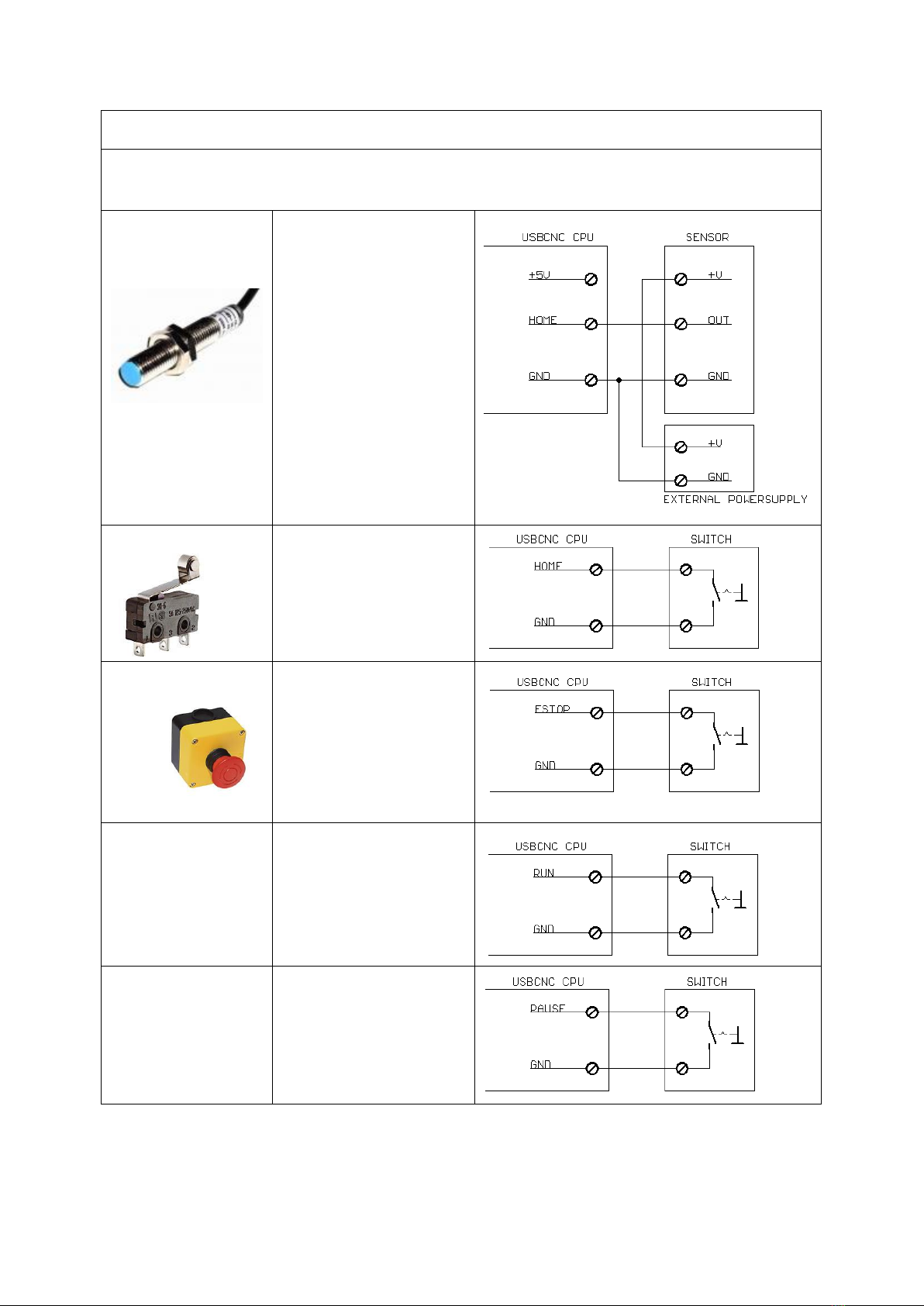
Connection of the inputs
HOME - ESTOP - PAUSE - RUN - HANDWHEEL - SPINDLE-SENSOR
INDUCTIVE HOME
SENSORS
NPN Type
SIMPLE HOME SWITCH
Normally Open Type
HomeInputSenseLevel = 0
Normally Closed Type
HomeInputSenseLevel = 1
ESTOP
SWITCH
Normally Open
EStopInputSenseLevel = 0
Normally Closed
EStopInputSenseLevel = 1
RUN SWITCH
Any push button switch
Auto detect
PAUSE SWITCH
Any push button switch
Normally closed

Handwheel
+5 Volt handwheel
Spindle sensor
This is required for
Lathe Thread cutting
Ask your dealer
Probe
A probe can be a normally
open or normally closed
switch.
Connection of the outputs
TOOL (Kress) - VFD - FLOOD - MIST -AUX1
TOOL FLOOD MIST AUX
SOLID STATE RELAY
This is the way I recommend,
Use a solid state relay.
A solid state relay causes no
sparks, very little EMV noise.

TOOL FLOOD MIST AUX
RELAY
Standard relays cause a lot of
EMV noise.
EMV noise can disturb the
USB communication.
I recommend to use
standard relay's only for low
power.
Never for get to apply a anti
parallel diode of 100 - 200
volt / 1 - 2 Amp.
Without this diode the CPU
may be damaged.
HF Spindle wit VFD
You can use the 0 - 10 volt
output together with the
tool output to control the
VFD.
Ask your VFD supplier how to make the connections
exactly.
LEDS
LED's from left to right
BOOTLOADER MODE
CNC MODE
Blue
+5 Volt and CPU 3.3Volt present.
Red
Error during programming.
Watchdog reset signal, 10
Hz pulse.
Yellow
Alternating flash indicate
boot loader active and
communication with USB
working.
FLASH=> ETHERNET ACTIVE
Green
FLASH => USB ACTIVE
Orange
Capture status, if on boot
loader remains active.
See also CPU5 configurator
tool.
10 pulses at startup to show
CNC firmware starting.
On if E-Stop activated.
Off if no E-Stop activated.

Upgrading USBCNC_CPU5A3 to USBCNC_CPU5A4
If you have bought a CPU5A3 and want to use the 4th axis, it is possible to upgrade. Via the 2nd setup page in
the USBCNC software, see explanation below:
CPUOPT: This is special for CPU5A.
This button allows to add the 4th axis function on a CPU5A3. So it upgrades
from 5A3 to 5A4.
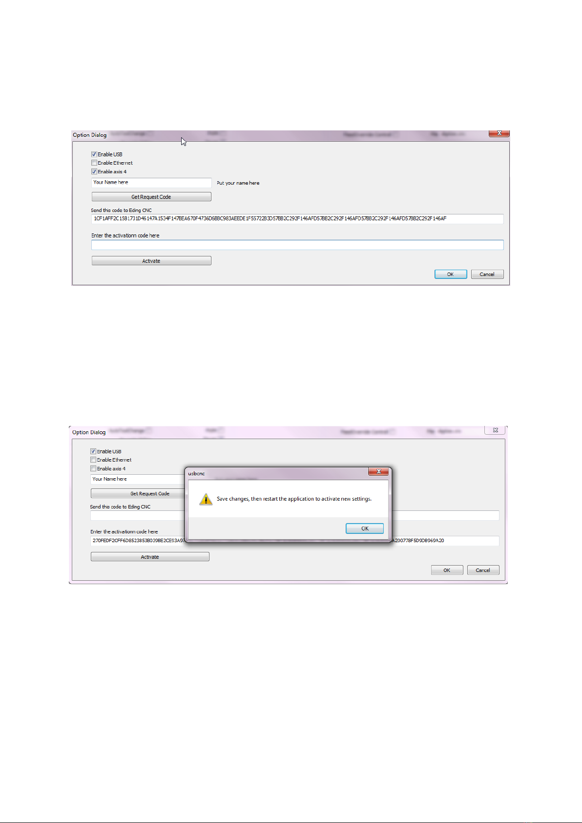
These are the steps to follow:
In the dialog check the "enable axis 4" checkbox, enter tour name and press
get request code:
Send the request code to the supplier.
Copy and paste it into an email and send it to your USBCNC supplier.
To do this double click the code, press ctrl-c, in your e-mail press control-v.
Your suplier will send you a activation code.
Copy and paste this into the activation code area. then press activate.
Do what the dialog tells you, press ok twice, press save changes. and restart.
When you press the CPU-OPT button again, you will see that the 4th
axis is enabled and that it is registered with your name.

Table of contents
Other Eding CNC Recording Equipment manuals

Popular Recording Equipment manuals by other brands

Pepperl+Fuchs
Pepperl+Fuchs IDENTControl IC-KP2-2HB18-2V1 manual

Rockwell Automation
Rockwell Automation AB Quality Allen-Bradley MicroLogix... user manual

Selah Effects
Selah Effects Quartz Timer V2 user manual

epiphan video
epiphan video AV.io HD user guide

DINUY
DINUY KNX EM KNT 002 Installation and commissioning

MGS
MGS Maya M24 manual


