Lynx greenMachine User manual

© 2011 - 2015 LYNX Technik AG all rights reserved
greenMachine
®
Reference Manual
greenMachine
callisto
3G/HD/SD Dual Channel SDI Frame Synchronizer
with Image and Audio Processing
Revision 1.5 – August 2016
LYNXTechnik AG
Broadcast Television Equipment
This Manual Supports Device Revisions:
callisto Revision
751
®

greenMachine callisto Reference Manual - Rev 1.5
Page 2 of 26
Table of Contents
Product Description .............................................................................................4
Product Overview.................................................................................................5
Functional Diagram..................................................................................................................... 5
Rear Connection Panel Overview............................................................................................... 6
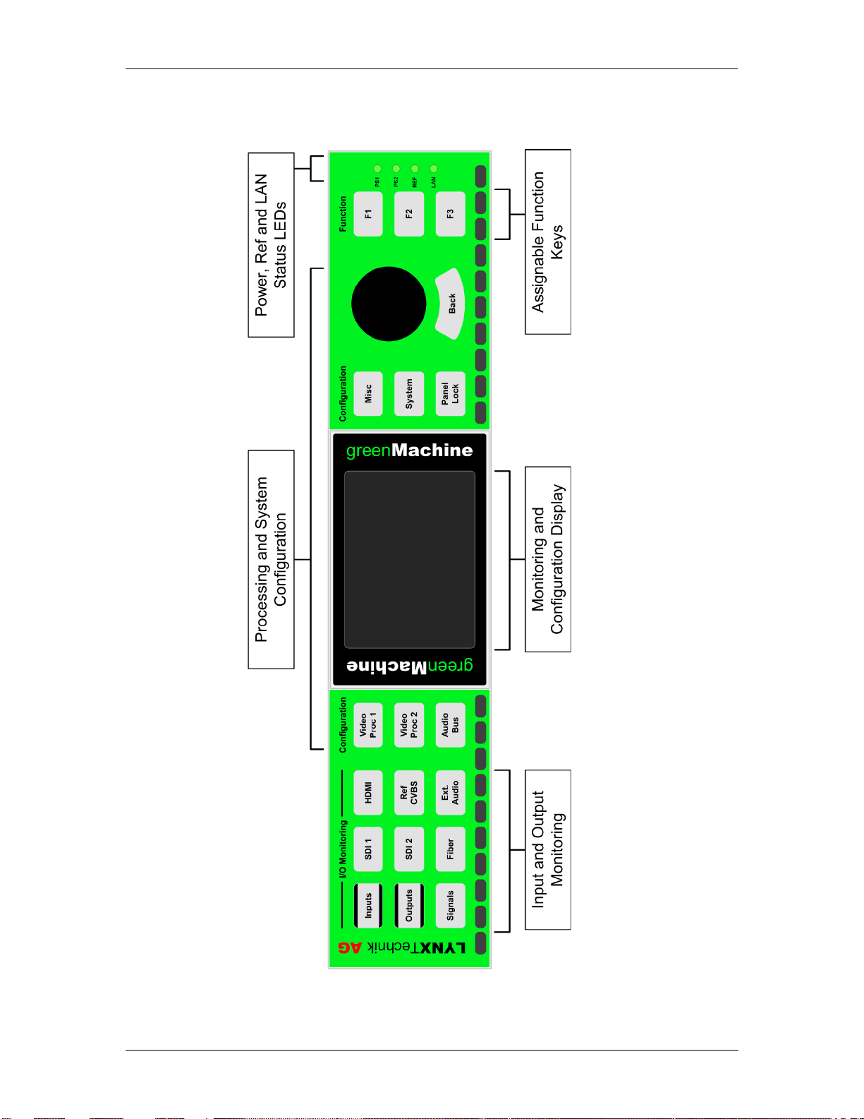
Control Panel Overview............................................................................................................... 7
Control Panel Description....................................................................................8
I/O Monitoring.............................................................................................................................. 8
“Signals” Button ...................................................................................................................... 8
“Inputs” Button ........................................................................................................................ 9
Detailed Signal Information..................................................................................................... 9
“Outputs” Button.................................................................................................................... 10
Processing Configuration.......................................................................................................... 11
Processing Configuration Menus.......................................................................................... 11
System Settings ........................................................................................................................ 14
IP Settings............................................................................................................................. 14
Panel Configuration .............................................................................................................. 14
F-Key Assign......................................................................................................................... 15
Reset..................................................................................................................................... 15
Health Parameters................................................................................................................ 15
Panel Lock................................................................................................................................. 16
PSU, LAN and Ref LEDs .......................................................................................................... 16
IP Remote Control..............................................................................................16
APPolo Control GUI .................................................................................................................. 16
Feature Description ...........................................................................................18
Supported SDI I/O Formats.................................................................................18
Supported HDMI Input Formats .........................................................................19
Supported Reference Input Formats..................................................................19
Frame Synchronization ......................................................................................20
Reference Source ..................................................................................................................... 20
TRS Error Behavior................................................................................................................... 20
Freeze Mode......................................................................................................................... 20
Output if no Input....................................................................................................................... 20
Audio Synchronization and Processing .............................................................21
Audio Content Detection ........................................................................................................... 21
Audio Synchronization............................................................................................................... 21
Audio Processing ...................................................................................................................... 21
Audio Routing............................................................................................................................ 21
External Audio....................................................................................................21
Sub-D 25 Pinning...................................................................................................................... 22
Analog Digital Configuration...................................................................................................... 22
Synchronization and Processing............................................................................................... 22

greenMachine callisto Reference Manual - Rev 1.5
Page 3 of 26
Up/Down/Cross Converter ..................................................................................23
Input Control Mode.................................................................................................................... 23
Input Image Aspect Ratio.......................................................................................................... 23
Output Image Format................................................................................................................ 23
Conversion Mode ...................................................................................................................... 23
Format Description Insertion..................................................................................................... 24
Input Cropping........................................................................................................................... 24
Output Sizing............................................................................................................................. 24
Video Processing ...............................................................................................24
Video Adjustments .................................................................................................................... 24
Aperture Correction................................................................................................................... 24
H/V Blanking.............................................................................................................................. 25
Test Pattern............................................................................................................................... 25
H-Flip......................................................................................................................................... 25
3G Output Format ..................................................................................................................... 25
Timing.................................................................................................................25
Technical Support..............................................................................................26
Contact Information...........................................................................................26

greenMachine callisto Reference Manual - Rev 1.5
Page 4 of 26
Product Description
The greenMachine callisto is the Swiss army knife for professional broadcast productions. At its
core the module is a dual channel video processing module with frame synchronizing and high
quality up/down/cross conversion. In addition to the video capability, the module includes an
internal audio bus with audio processing as well as synchronizing functionality.
The greenMachine callisto offers a multitude of different video and audio in- and output
connections. Together with the two high quality up/down/cross converters the callisto is the ideal
solution for long list of applications.
The greenMachine products are standalone processing modules with an intuitive control interface
with an LCD display for the graphical menu as well as video input or output monitoring.
In addition the greenMachine products can be fully integrated into the LYNX APPolo Control
System adding the long list of APPolo feature such as flexGUI, AutoControl, CustomControl and
many more.

greenMachine callisto Reference Manual - Rev 1.5
Page 5 of 26
Product Overview
Functional Diagram
Image 1: greenMachine callisto - Functional Diagram

greenMachine callisto Reference Manual - Rev 1.5
Page 6 of 26
Rear Connection Panel Overview
Image 2: greenMachine callisto - Backpanel

greenMachine callisto Reference Manual - Rev 1.5
Page 7 of 26
Control Panel Overview
Image 3: greenMachine callisto - Front Control Panel

greenMachine callisto Reference Manual - Rev 1.5
Page 8 of 26
Control Panel Description
The front control panel allows the complete configuration of the module in addition to detailed
monitoring features of the input and output signals. The following chapters will outline the
functionalities.
I/O Monitoring
The nine push buttons located on the left hand side of the control panel in conjunction with the
local display provide everything that is required for a detailed input and/or output signal
monitoring.
“Signals” Button
Pressing the “Signals” button located on the bottom left of the control panel will result in an input
and output signals overview being shown in the display. The “Signals” button will be illuminated
white to indicate that it is selected.
Pressing the “Signals” button a second time will show the left hand side of a signal flow overview
of the module including the status indication of the video and reference inputs and outputs.
Pressing the “Signals” button another time will pan to the right hand side of this flow diagram.
When either the left or right hand side of the diagram is shown in the display, the rotary push
encoder can be used to pan between the left and right side.
Pressing the “Signals” button when the display shows the right hand side of the flow diagram, will
switch back to the signals overview page.
Image 4: “Signals” - Monitoring of all Input and Output Signals
Image 5: “Signals” Display Navigation

greenMachine callisto Reference Manual - Rev 1.5
Page 9 of 26
“Inputs” Button
Pressing the “Inputs” button will result in two things happening:
1. The display will show more detailed information for all the input signals.
2. The signal buttons (e.g. SDI 1, SDI 2, Fiber, HDMI, etc.) now will be illuminated with colors
according to the input signals. The “Inputs” button itself will be illuminated white to indicate
that it is selected. This button status indication will remain unless the “Outputs” button is
pressed.
Detailed Signal Information
To get detailed information for a specific input signal simply press the signal button (e.g. SDI 1)
when in “Inputs” mode. The chosen signal button will be illuminated more brightly than the other
ones to indicate that it is selected.
Image 6: “Inputs” – Monitoring Overview
Image 7: Correlation of button illumination and Signal Status
Image 8: Detailed Input Monitoring

greenMachine callisto Reference Manual - Rev 1.5
Page 10 of 26
The detected input standard of the selected input will be shown at the top of the display. The
bottom of the display will list which internal video processor the signal is assigned to (none, Video
Proc 1 and/or Video Proc 2).
Pressing the same signal button repeatedly will toggle between different pages with more
information. The following example will show the information pages for the SDI inputs.
1. Signal Status Overview
Depending on the type of input (i.e. electrical SDI or Fiber) this page will show details
about the input format, available audio, optical input budget or similar.
2. Preview
The display will show a preview image of the selected input that is assigned to one of
the video processors. This feature is only available for the input signal(s) assigned to
one of the processors.
3. Audio Level Meters
The display will show audio level meters of the selected input that is assigned to one
of the video processors. This feature is only available for the input signal(s) assigned
to one of the processors.
(This feature will be available in one of the next version)
4. Meta Data Information
The display will show the detected meta data information of the selected input that is
assigned to one of the video processors. This feature is only available for the input
signal(s) assigned to one of the processors.
“Outputs” Button
The “Outputs” button works exactly the same way as the “Inputs” button with the difference being
that the monitoring is based on the output signals instead of the input signals.
- The display will show an overview of all the output signals after pressing the
“Outputs” button.
- The signal buttons (e.g. SDI 1, SDI 2, Fiber, HDMI, etc.) will be illuminated with colors
according to the output signals.
- Pressing a signal button when in output mode will show the Detailed Signal
Information in the same way as in input mode (i.e. pressing the signal button
repeatedly will toggle between different information pages – preview and audio level
meters will be available in one of the next versions).
Image 9: Detailed Signal Information Pages

greenMachine callisto Reference Manual - Rev 1.5
Page 11 of 26
Processing Configuration
The three buttons to the left of the display as well as the top button on the right of the display
access the four processing configuration menus in the display.
Together with the rotary push encoder and the back button these four configuration menus are all
that is required to configure the processing of the callisto greenMachine.
Processing Configuration Menus
The processing configuration menus are generally grouped as shown in the functional diagram
below (Image 11). Settings that logically can’t be associated to any of these three categories can
be found in the “Misc” menu (e.g. storing/loading presets)
Image 10: Configuration Controls
Image 11: Processing Overview

greenMachine callisto Reference Manual - Rev 1.5
Page 12 of 26
The structure and usage of the configuration menus works as follows.
The areas on the left and right side of the display show the active menu items. Turning the rotary
push encoder will navigate between these different menu items. The inverted menu item (i.e. dark
gray with white text) is the currently selected one. It’s possible that there are more than six menu
items. In this case there will be more pages available. These are indicated by the circles at the
bottom of the center part of the menu. The pale gray circle indicates which page is currently
selected. To change pages, simply continue turning the rotary encoder beyond the last icon (next
page) or the first icon (previous page).
There are two different shapes for the menu items. The square boxes are menus containing at
least one additional menu level. When selected the middle part of the display will show a preview
of what settings and/or menus are available within this menu (Image 13). Pressing the encoder
will enter the selected menu. Pressing the “Back” button below the encoder will return to the lower
menu level.
Image 13: Preview of Menu Content
Image 12: Active Menu Items

greenMachine callisto Reference Manual - Rev 1.5
Page 13 of 26
The hexagon shaped items are parameters. When one of these menu items is selected, the
middle area of the display will show the type of parameter and the current setting (Image 14).
To edit the parameter press the encoder. When in edit mode, turn the encoder. To exit the edit
mode, press either the encoder or the “Back” button.
Image 14: Parameter Preview

greenMachine callisto Reference Manual - Rev 1.5
Page 14 of 26
System Settings
The “System” menu contains all setting and monitoring possibilities that are not related to the
processing.
IP Settings
This menu provides all settings required for the IP configuration of the greenMachine.
- Set IP Mode
Choose between “Static” IP settings or “DHCP”
- Set IP Address
This menu allows the reading (DHCP mode) and setting of the IP address if the “IP
Mode” is set to “Static”. To adjust the IP address, press the encoder and the first
block of three digits can be set by turning the encoder. Press the encoder to confirm
the first block and to edit the second. Repeat this procedure until you have set all four
three digit blocks of the IP address (Image 15).
After confirming the four IP address block, a “Confirmation Request” will be shown in
the display. Confirm to finalize the IP address settings or press “Cancel” and the IP
address will not be adjusted. Pressing the “Back” button at any time while editing the
IP address will exit the edit mode and the IP address will not be adjusted.
- Set Gateway
This menu allows the adjustment of the IP Gateway if the “IP Mode” is set to “Static”.
- Set Network Mask
This menu allows the adjustment of the IP Network Mask if the “IP Mode” is set to
“Static”.
Panel Configuration
- Brightness
This menu allows the adjustment of the brightness of the display and button
illumination.
Image 15: IP Setting Adjustment

greenMachine callisto Reference Manual - Rev 1.5
Page 15 of 26
Image 17
- Timeout
When turned on, the panel will go into a snooze mode after the selected timeout. The
panel will turn on again if any of the controls are adjusted.
F-Key Assign
This menu provides the possibility to assign stored presets (to store presets, press the “Misc”
menu button and enter the Preset menu) to the three F-Keys on the far right of the control panel
(Image 16).
Once a Preset has been assigned to an F-Key, pressing this function button will load the
previously assigned preset after accepting the confirmation request.
Reset
There are two types of reset available:
- Reset Module
Using this reset will only set the processing relevant parameters back to factory
default. In other words all parameters that can be configured via the Video Proc 1/2,
“Audio Bus” and “Misc” menus.
Note: The stored presets won’t be affected by the reset.
- Reset Controller
This reset will set all system settings back to factory default excluding the IP settings.
Health Parameters
This menu provides health monitoring parameters for the greenMachine. If one of these
parameters should be within a warning or critical level, the “System” menu button will be
illuminated according to the alarm state and in addition the parameter in question on the display
menu will have a colored frame.
Image 16: Function Keys

greenMachine callisto Reference Manual - Rev 1.5
Page 16 of 26
Image 18: Connecting the greenMachine callisto to the APPolo Control Software
Panel Lock
The “Panel Lock” button at the bottom right of the display activates or de-activated the panel lock.
To lock or to unlock, press and hold the button for 3 seconds.
When in lock mode, the “Panel Lock” button will be illuminated red and the configuration buttons
will be dimmed. However, the I/O Monitoring functionality will still available.
PSU, LAN and Ref LEDs
The four LEDs located on the far right of the control panel provide a simple status monitoring of
the power supplies, LED activity and reference input.
- PSU 1/2
If a power supply is connected the LED will be green. If not, the LED will be red.
- LAN
This LED will indicate if a LAN connection is established.
- REF
This LED is a simple monitoring of the reference input.
oGreen: Valid reference detected
oYellow: Reference to video mismatch
oRed: No valid reference detected
IP Remote Control
The greenMachine can be used as a stand-alone module but at the same time it is fully integrated
into the LYNX APPolo Control System and in addition can be remote controlled and/or monitored
via the LYNX IP remote control protocol or SNMP.
APPolo Control GUI
To connect the greenMachine to the APPolo Control GUI (9.0.0 or higher), make sure that the
module and the PC running the software are in the same IP range (see IP Settings for more
details).
Start the APPolo Control software and open the “Connection Manager” from the “Tools” menu.
Select the “Network Connections Editor” tab. This editor will list the detected the detected
greenMachine modules in the right column. To connect them to the APPolo GUI, simply drag and
drop this greenMachine entry from the right column onto the “My Computer” entry in the left
column.
Once this is done, you can select the “Main Control” from the Tools menu to control and monitor
the greenMachine.
The device tree on the left hand side will show two entries (Image 19).

greenMachine callisto Reference Manual - Rev 1.5
Page 17 of 26
Image 19: callisto in the Device Tree
Image 20: The greenMachine callisto flexGUI view
If you select the “greenMachine <IP-Address>” entry you will access the system settings of the
greenMachine.
Selecting the “callisto” will show the processing flexGUI of the greenMachine (Image 20).
For an introduction video of the flexGUI, please visit our homepage http://www.lynx-
technik.com/en/products/appolo-control/).

greenMachine callisto Reference Manual - Rev 1.5
Page 18 of 26
Feature Description
The greenMachine callisto is a high performance 3G/HD/SD dual channel frame synchronizer
with full embedded and external audio support. For each frame synchronizer channel an optional
high quality Up/Down/Cross converter extension is available. Each converter extension can
convert between the different supported input and output standards in addition to freely cropping
and sizing the video images.
Two electrical 3G/HD/SD SDI inputs and outputs are available on the greenMachine callisto. In
addition to this it has an HDMI input and output as well as an optional fiber in and output.
A Sub-D 25 connector provides 4 audio input and output connections that can be configured for
either analog or digital audio.
Supported SDI I/O Formats
The module has two multi-format serial digital inputs with automatic input detection. The module
will detect the following input standards and configure the input stage automatically for operation
in the connected format. The supported SDI output standards are identical to the input standards.
SDTV Formats
HDTV Formats
525 / 59.94Hz
1080i / 50Hz
625 / 50Hz
1080i / 59.94Hz
1080i / 60Hz
1080p / 23.98Hz
1080p / 24Hz
1080p / 25Hz
1080p / 29.97Hz
1080p / 30Hz
1080psf / 23.98Hz
3GBit/s Formats Level A
1080psf / 24Hz
1080p / 50Hz
1080psf / 25Hz
1080p / 59.94Hz
720p / 23.98Hz
1080p / 60Hz
720p / 24Hz
720p / 25Hz
720p / 29.97Hz
3GBit/s Formats Level B Dual Link
720p / 30Hz
1080p / 50Hz
720p / 50Hz
1080p / 59.94Hz
720p / 59.94Hz
1080p / 60Hz
720p / 60Hz
As the synchronizer uses a single studio reference input both input signals should be the same
input frequency range (odd or even frame rate) as the reference for normal operation.
The output format frequency (or frame rate) is determined by the connected reference signal and
the output will remain fixed to this reference regardless of the connected input signals.

greenMachine callisto Reference Manual - Rev 1.5
Page 19 of 26
Supported HDMI Input Formats
The module has an HDMI input with automatic input detection. The module will detect the
following input standards and configure the input stage automatically for operation in the
connected format. The supported HDMI output standards are identical to the input standards.
SDTV Formats
HDTV Formats
525 / 59.94Hz
1080i / 50Hz
625 / 50Hz
1080i / 59.94Hz
1080i / 60Hz
3GBit/s Formats
1080p / 23.98Hz
1080p / 50Hz
1080p / 24Hz
1080p / 59.94Hz
1080p / 25Hz
1080p / 60Hz
1080p / 29.97Hz
1080p / 30Hz
720p / 23.98Hz
720p / 24Hz
720p / 25Hz
720p / 29.97Hz
720p / 30Hz
720p / 50Hz
720p / 59.94Hz
720p / 60Hz
As the synchronizer uses a single studio reference input both input signals should be the same
input frequency range (odd or even frame rate) as the reference for normal operation.
The output format frequency (or frame rate) is determined by the connected reference signal and
the output will remain fixed to this reference regardless of the connected input signals.
Supported Reference Input Formats
The module has a very flexible input reference stage which facilitates the use of either SDTV
analog bi-phase sync (i.e. black burst) or HDTV analog tri-level sync. The reference input is
“cross lock” compatible so an SDTV reference can be used to frequency lock HDTV signals (and
vice versa). The connected reference is auto detected and the synchronizer automatically
configures the outputs to the frame rate of the connected reference signal.
SDTV Analog Bi-Level Sync
HDTV Analog Tri-Level Sync
525 / 59.94Hz
1080i / 50Hz
625 / 50Hz
1080i / 59.94Hz
1080i / 60Hz
HDTV Analog Tri-Level Sync
1080p / 23.98Hz
720p / 23.98Hz
1080p / 24Hz
720p / 24Hz
1080p / 25Hz
720p / 25Hz
1080p / 29.97Hz
720p / 29.97Hz
1080p / 30Hz
720p / 30Hz
1080psf / 23.98Hz
720p / 50Hz
1080psf / 24Hz
720p / 59.94Hz
1080psf / 25Hz
720p / 60Hz

greenMachine callisto Reference Manual - Rev 1.5
Page 20 of 26
Frame Synchronization
The algorithms used for frame synchronization are extremely robust and very tolerant of poor
input signals. The Synchronizer uses “Flywheel” functionality. This allows the module to recover
from any missing sync pulses on the input signal(s) by predicting where they should be and then
re-inserting them.
If no converters are active, the frame synchronizer passes the video in the connected input
format.
Reference Source
The frame synchronizers can be referenced by the external reference input or either one of the
video processing paths. The reference source is a global setting i.e. both frame synchronizers
use the same reference source and can’t be set individually.
If the reference source is set to external reference and no external reference is connected, the
frame synchronizer is in free run mode.
TRS Error Behavior
In addition to synchronizing the video signal(s) to the reference source the frame synchronizers
can also detect TRS errors of the video signal. The frame synchronizers can individually be
configured to either ignore the TRS error or to freeze on TRS error. The freeze behavior is
determined by the freeze mode setting.
Freeze Mode
The Freeze Mode determines the behavior of the individual frame synchronizers when
set to “Freeze on TRS” and detecting a TRS error on the processed video signal.
Possible selections are:
- Freeze Field 1
Only Field 1 will be frozen and output. This only applies for interlaced standards. For
progressive standards the frame synchronizer will automatically freeze frame.
- Freeze Field 2
Only Field 2 will be frozen and output. This only applies for interlaced standards. For
progressive standards the frame synchronizer will automatically freeze frame.
- Freeze Frame
The frame synchronizer will freeze the frame on TRS error.
- Test Pattern
When detecting a TRS error the frame synchronizer will output a test pattern. The
test pattern is identical to the one selected for the test pattern generator.
This setting is ideal to identify TRS errors on the video signal.
Output if no Input
This setting determines the behavior of the frame synchronizer if the processed video input signal
is lost. Three possible selections are available.
- Freeze (outputs the last frame)
- Black (outputs a black signal)
- Test Pattern (outputs the selected test pattern)
Table of contents
Other Lynx Recording Equipment manuals