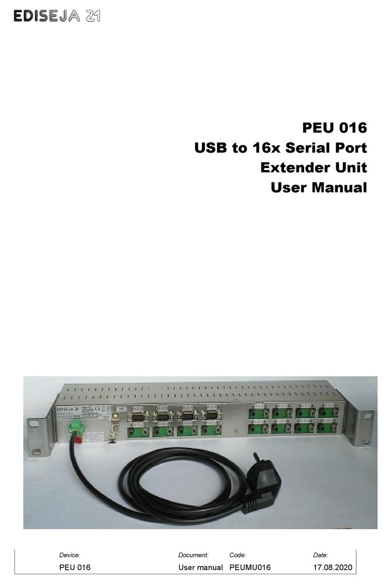
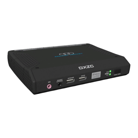
Ediseja 21 PEU 016 Installation instructions

Ediseja 21, razvoj elektronskih naprav, d.o.o.
Stegne 21C, 1000 Ljubljana, Slovenia – EU Tel: 00 386 51 643 411
Communication port Multimode Fiber Optic
(interface type 6, 6N, 7 and 7N) Communication port RS232 (interface type 2)
Type multimode fiber optic Type RS232
Wave lenght 820 nm Direction full duplex
Fiber size 50/125 µm, 62,5/125 µm,
100/140 µm, 200 µmSpeed setting up to 230 kbit/s
Optical output power -18 dB Distance up to 15 m
Reciver sensitivity -24 dB Isolation isolated 500 V DC
Laser class I (IEC 60825-1) Connector type DB9 male
Direction full duplex Lines in 1 (Rx)
Speed up to 230 kbit/s Lines out 1 (Tx)
Input 1 receiver (grey connector)
Output 1 transmitter (white connector) Communication port RS485 (interface type 5)
Logic light ON (negative logic) or OFF
(positive logic) in idle state set
by switches
Type RS485
Distance up to 500 m Direction half duplex
Connector type ST (interface 6 & 6N
SMA (interface 7 & 7N Speed setting up to 115,2 kbit/s
Distance up to 1200 m
Isolation isolated 500 V DC
Connector type DB9 female
Termination 120 Ohm
Number of devices
on RS485 bus 32 max
ORDERING CODE:
PEU 016 /
. . . . . . . . . . . . . . . . . .
Power supply voltage:
110 - 220 V DC, 230 V AC .................. 5
Master port:
USB ......................................................... U
Ethernet (in development) ....................... E
Reserved for future use:
Reserved for future use ................................... x
Interfaces (up to 16 max!):
None ................................................................................................................................. N or leave empty
RS232 port (isolated, Rx & Tx support, DB9M connector) ..................................................................... 2
RS485 port (isolated, half duplex, DB9F connector) ............................................................................... 5
Multimode (820 nm) fiber optic port (ST connector) ............................................................................... 6
Multimode (820 nm) fiber optic port-NEGATIVE logic (idle state-light ON*) (ST conn.) ........................ 6N
Multimode (820 nm) fiber optic port (SMA connector) ........................................................................... 7
Multimode (820 nm) fiber optic port-NEGATIVE logic (idle state-light ON*) (SMA conn.) ...................... 7N
* User can set fiber optic logic by opening the device and set jumpers accordingly. Recommended for technically
skilled personell.
4 PEU 016 Safety instruct. PEUMIU16 18.08.2020
Ediseja 21, razvoj elektronskih naprav, d.o.o.
Stegne 21C, 1000 Ljubljana, Slovenia – EU Tel: 00 386 51 643 411
PEU 016 - USB TO 16x SERIAL PORT EXTENDER UNIT SAFETY INSTRUCTIONS
(for detailed instructions
and user manual please see our web page)
EXPLANATION OF THE SYMBOLS
GENERAL INFORMATION
These paper contain the information that is necessary for the proper and safe operation of the described devices. This
paper is intended for technically qualified personnel.
Warning! Hazardous voltage is present inside the device during operation. Disregarding of safety rules can
result in severe personal injury or property damage.
Only qualified personnel may work with described devices after being familiar with warnings and safety notices
in this paper and other safety regulations.
Warning! Device must operate completely assembled! Device must be used as described. No modifications of
the device should be made.
Warning! Do not open device while it is energized! Hazardous voltage is present inside the device. Disconnect
all connectors before opening!
Warning! If device is damaged disconnect it from power supply! Send it to the manufacturer for inspection.
Warning! Connect to earth before attaching power supply!
Device opening: follow the steps 1, 2 & 3, remove top of the device
Removing cards for fiber optic logic change: for ports 1-8: unscrew 4 screws inside the device that holds the cards, take a
picture of flat cable connetors is possible, disconnect flat cables, remove both cards simultaneously; for ports 9-16:
unscrew 4 distance bolts that holds the cards, remove both cards simultaneously.
Device 19" rack or surface mounting holding bracket position change: follow the steps 2, 4, 5, reverse step 2 & 4 then
follow the steps 3, 6, 7, reverse step 3 & 6. Step 8: attack DIN35 additional holder if needed (not included).
PEU 016 Safety instruct. PEUMIU16 18.08.2020 1

Ediseja 21, razvoj elektronskih naprav, d.o.o.
Stegne 21C, 1000 Ljubljana, Slovenia – EU Tel: 00 386 51 643 411
SCHEMATIC
FIBER OPTIC LOGIC JUMPER SETTING (check "Device opening" section of this document)
Logic Light in idle state
Positive OFF
Negative ON
Fiber optic logic can be set for
each port with two jumpers.
Picture displays example for port
1 & 2 negative logic setting and
port 3 & 4 positive logic setting.
RS485 PORT
INSTALLATION
Warning! Hazardous voltage is present inside the device during operation. Disregarding of safety rules can
result in severe personal injury or property damage.
Only qualified personnel may work with described devices after being familiar with warnings and safety notices
in this paper and other safety regulations.
2 PEU 016 Safety instruct. PEUMIU16 18.08.2020
Ediseja 21, razvoj elektronskih naprav, d.o.o.
Stegne 21C, 1000 Ljubljana, Slovenia – EU Tel: 00 386 51 643 411
Following instruction must be taken into consideration:
The device must be accessible to qualified personnel only.
The device is permitted to operate in enclosed housing or cabinet only.
The device location must be vibration-free.
The admisible operating temperature must be observed.
Check the device for damage at unpacking. If device is damaged it must not be installed but it should be send
to the manufacturer for repair.
The device should not be opened expect if fiber ptic logic change is necessary.
Attach ground wire before attaching power supply. Device must be grounded during operation!
Single core or stranded wire 0,5 – 2,5 mm2 must be used for power supply connection. If stranded wire is
used, ferrules must be used to prevent fraying. Recommended stripping lenght is 5 mm.
Protective earthing wire must be terminated with tinned copper ear terminal.
SOFTWARE
Device has integrated FT4232 chip. Please download needed driver from:
https://www.ftdichip.com/Drivers/VCP.htm
Note!
Application which connects to the serial ports must be started after all ports are recognised by the
operating system. Ports must be recognised by the operating system every time that PC or PEU device is
powered and/or USB cable is connected to the PC. If this requirement is not followed, some ports may not work!
COMMISSIONING
Following instruction must be taken into consideration:
Device must operate completely assembled! Device must be used as described. No modifications of the
device should be made.
Attach ground wire before attaching power supply. Device must be grounded during operation!
Check if the power supply voltage complies with device operation voltage.
Do not open device while it is energized! Hazardous voltage is present inside the device.
TECHNICAL DATA
Power supply Other data
Rated input
voltage PEU 016 / 5.... 110 V-220 V DC
230 V AC Weight approx. 1,3 kg
Permissible
voltage range PEU 016 / 5.... 88 V–370 V DC
85 V–264 V AC Dimensions (W) 19" rack, (H) 1U (44
mm), (D) 115mm or 87 mm+
connectors
Frequency 50 Hz Temperature range 0 °C to +55 °C
Power
consumption all types 10 W 15 VA Humidity operating up to 95 % (noncondensing)
Voltage dips > 20 ms Enclosure Material: inox, IP40
Connector
type screw type „MSTB“ Phoenix 2pin Mount type standard 19" rack, 1U
Power supply
wire
crossection 0,5 – 2,5 mm
2
Class I
type single or stranded
wire Overvoltage category II
voltage rating 500 V
colour depends on used
standard
Ground wire
crossection Cu, 2,5 mm
2
colour yellow-green or
natural (non
isolated)
PEU 016 Safety instruct. PEUMIU16 18.08.2020 3
Other manuals for PEU 016
1
Other Ediseja 21 Extender manuals
