Ediseja 21 PEU 016 User manual


PEU 016 - USB to 16x Serial Port Extender Unit
Content
1 PREFACE.......................................................................................................3
2 PEU 016 SYSTEM..........................................................................................5
2.1 DESCRIPTION..................................................................................................................... 5
2.2 TYPICAL APPLICATION..................................................................................................... 5
2.3 APPEARANCE..................................................................................................................... 5
3 SCHEMATIC...................................................................................................6
4 INSTALLATION..............................................................................................7
4.1 DE ICE OPENING AND 19" RACK HOLDING BRACKET POSITION CHANGE...............7
4.2 FIBER OPTIC LOGIC SETTINGS........................................................................................8
4.3 USB DRI ERS INSTALLATION..........................................................................................8
4.3.1 V RTUAL COM PORT DR VERS.......................................................................................8
4.3.1.1 V RTUAL COM PORT DR VERS EXECUTABLE SETUP FOR W NDOWS..................8
4.3.2 DLL DR VERS (for advanced users)..................................................................................9
4.4 SERIAL PORT APPLICATION START................................................................................9
4.5 MOUNTING........................................................................................................................ 10
5 COMMISSIONING & MAINTENACE..........................................................11
5.1 COMMISSIONING.............................................................................................................. 11
5.2 MAINTENANCE................................................................................................................. 11
6 TECHNICAL DATA......................................................................................12
7 DIMENSIONS...............................................................................................14
8 ORDERING...................................................................................................16
Page: Device: Document: Code: Date:
2 PEU 016 User manual PEUMU016 17.08.2020

PEU 016 - USB to 16x Serial Port Extender Unit
1 PREFACE
Liability statement
We have checked the contents of this manual to ensure that the descriptions of both hardware and
software are as accurate as possible. However, deviations may occur so that no liability can be accepted
for any errors or omissions contained in the information given.
The contents of this manual will be checked in periodical intervals, corrections will be made in the
following editions.
We reserve the right to make technical improvements without notice.
Contact
f you have any questions or comments related to this product please contact us on:
Ediseja 21 d.o.o.
Stegne 21C
1000 Ljubljana
Slovenia – EU
Tel: 00 386 51 643 411
Email: grega.flander@ediseja21.com
www.ediseja21.com
Copyright
Copyright © Ediseja 21, 2020. All rights reserved.
Explanation of the symbols
Read the instructions!
Device was tested with 2 kV AC voltage to check the device insulation.
Device ground terminal.
Waste Electrical and Electronic Equipment (WEEE) Directive 2002/96/EC; the affixed
product label indicates that you must not discard this electrical/electronic product in
domestic household waste.
Warnings
n this paper the following terms are used:
Danger
indicates that death, severe personal injury or substantial property damage will result if proper precautions
are not taken.
Warning
indicates that death, severe personal injury or substantial property damage can result if proper
precautions are not taken.
Device: Document: Code: Date: Page:
PEU 016 User manual PEUMU016 17.08.2020 3

PEU 016 - USB to 16x Serial Port Extender Unit
Caution
indicates that minor personal injury or property damage can result if proper precautions are not taken.
This particularly applies to damage on or in the device itself.
General information
These paper contain the information that is necessary for the proper and safe operation of the described
devices. This paper is intended for technically qualified personnel.
Warning!
Hazardous voltage is present inside the device during operation. Disregarding of safety
rules can result in severe personal injury or property damage.
Only qualified personnel may work with described devices after being familiar with warnings and
safety notices in this paper and other safety regulations.
Warning!
Device must operate completely assembled! Device must be used as described. No
modifications of the device should be made.
Warning!
Do not open device while it is energized! Hazardous voltage is present inside the
device. Disconnect all connectors before opening!
Warning!
If device is damaged disconnect it from power supply! Send it to the manufacturer for
inspection.
Warning!
Connect to earth before attaching power supply!
Page: Device: Document: Code: Date:
4 PEU 016 User manual PEUMU016 17.08.2020

PEU 016 - USB to 16x Serial Port Extender Unit
2 PEU 016 SYSTEM
2.1 DESCRIPTION
Port extender unit (PEU 016) is system for extending computer serial ports. t adds 16 serial ports to the
operating system from single USB port. t galvanicaly separates RS232 to prevents ground loops and
increases computer's electromagnetic immunity (EM ). Besides RS232 it additionaly provides RS485 and
multimode fiber optic ports for connection to protection relays, voltage regulators, ect. Number of each
port is user selectable.
PEU system is assembled from PEU 016 device and appropriate drivers for multiple operating systems.
PEU 016 housing is made from inox and intended for 19" rack mounting or surface mounting.
This device is intended for use in cubicles and cabinets in all kinds of power production, transmission and
distribution stations. t requires no maintenace. All normaly used connectors, switches and light indicators
are accessed at the front side of the device. Light indicators indicate communication activity of each port.
2.2 TYPICAL APPLICATION
2.3 APPEARANCE
Device: Document: Code: Date: Page:
PEU 016 User manual PEUMU016 17.08.2020 5
Picture 2: Front view
Picture 1: Typical application

PEU 016 - USB to 16x Serial Port Extender Unit
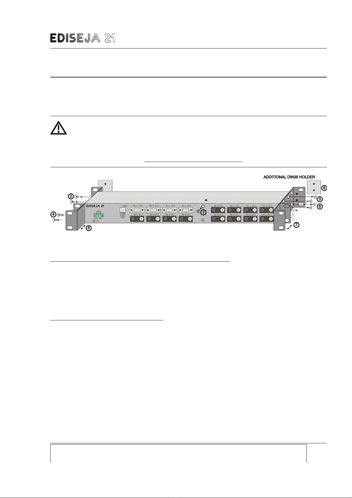
4 INSTALLATION
4.1 DE ICE OPENING AND 19" RACK HOLDING BRACKET
POSITION CHANGE
Warning!
Hazardous voltage is present inside the device during operation. Disregarding of safety
rules can result in severe personal injury or property damage.
Before following steps are made, unplug ALL cables from the device especially power supply!
Device 19" rack or surface mounting holding bracket position change:
follow the steps
- 3 (unscrew 2 upper screws)
- 6 (unscrew 2 lower screws)
- 7 (adjust & turn 19“ rack holding bracket according to your needs)
- reverse step 3 & 6
- then follow the steps 2, 4, 5, reverse step 2 & 4.
- Step 8: attach D N35 additional holder if needed (not included).
Removing cards for fiber optic logic change:
follow the steps
- 1 (unscrew 1 upper screws)
- 2 (unscrew 2 upper screws on the left side)
- 3 (unscrew 2 upper screws on the right side)
- remove top of the device
for ports 1-8:
- unscrew 4 screws inside the device that holds the cards
- take a picture of flat cable connetors is possible
- move both boards simultaneously
- disconnect flat cables
- remove both boards simultaneously.
for ports 9-16:
- unscrew 4 distance bolts that holds the cards
- remove both boards simultaneously.
Device: Document: Code: Date: Page:
PEU 016 User manual PEUMU016 17.08.2020 7
Picture 4: Device opening & holding bracket po ition change tep
PEU 016 - USB to 16x Serial Port Extender Unit
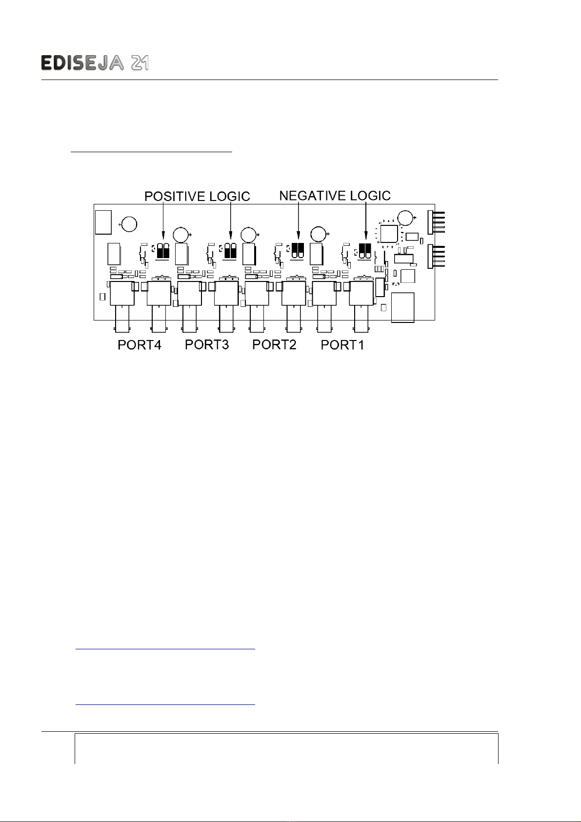
4.2 FIBER OPTIC LOGIC SETTINGS
Fiber optic port can operate with the positve logic (light OFF in idle state) or with the negative logic (light
ON in idle state). User can set the logic with jumper settings on each fiber optic port inside the device. To
do so, unplug ALL cables from the device. And see previous chapter for opening the device.
After board(s) are removed from the device, set the jumpers according to the requirements.
After jumper setting is completed, assemble the device in reverse order.
4.3 USB DRI ERS INSTALLATION
4.3.1 IRTUAL COM PORT DRI ERS
Virtual COM port (VCP) drivers cause the USB device to appear as an additional COM port available to
the PC. Application software can access the USB device in the same way as it would access a standard
COM port.
USB drivers are available for many operating systems:
Windows 7, Windows Server 2008 R2 and Windows 8, 8.1, Windows server 2012 R2,
Windows Server 2016 and Windows 10
Linux supported in Ubuntu 11.10, kernel 3.0.0-19
Mac OS X 10.3 and above
Windows CE 4.2-5.2
Windows CE 6.0/7.0
Windows CE 2013
Drivers & more information can be obtained at:
https://www.ftdichip.com/Drivers/VCP.htm
4.3.1.1 IRTUAL COM PORT DRI ERS EXECUTABLE SETUP FOR WINDOWS
For setup executable file click on link in red frame on
https://www.ftdichip.com/Drivers/VCP.htm
web site:
Page: Device: Document: Code: Date:
8 PEU 016 User manual PEUMU016 17.08.2020
Picture 5: Fiber optic etting : left - po itive logic (light OFF in idle tate)
right - negative logic (light ON in idle tate)

PEU 016 - USB to 16x Serial Port Extender Unit
Download the file, unzip it and run that exe file. (Currently named CDM21228_Setup.exe).
Wait until installation is complete, reboot PC if it is instructed so.
Connect PEU 016 to power supply.
Connect PEU 016 USB cable to the computer.
Wait operating system to find and install all that is needed.
After installation is completed, there should be new serial ports installed into the computer's system.
Number of new ports depends on PEU 016 device type.
f not, reboot the computer. f that does not help, deinstall serial ports, unplug USB cable reboot the
computer and repeat previously described procedure.
4.3.2 DLL DRI ERS (for advanced users)
D2XX drivers allow direct access to the USB device through a DLL. Application software can access the
USB device through a series of DLL function calls. Drivers & more information can be obtained at:
https://www.ftdichip.com/Drivers/D2XX.htm
4.4 SERIAL PORT APPLICATION START
Note!
Application which connects to the serial ports must be started after all ports are recognised by the
operating system. Ports must be recognised by the operating system every time that PC or PEU
device is powered and/or USB cable is connected to the PC. If this requirement is not followed,
some ports may not work!
Device: Document: Code: Date: Page:
PEU 016 User manual PEUMU016 17.08.2020 9

PEU 016 - USB to 16x Serial Port Extender Unit
4.5 MOUNTING
Warning!
Hazardous voltage is present inside the device during operation. Disregarding of safety
rules can result in severe personal injury or property damage.
Only qualified personnel may work with described devices after being familiar with warnings and
safety notices in this paper and other safety regulations.
Following instruction must be taken into consideration:
The device must be accessible to qualified personnel only.
The device is permitted to operate in enclosed housing or cabinet only.
The device location must be vibration-free.
The admisible operating temperature must be observed.
Check the device for damage at unpacking. f device is damaged it must not be installed
but it should be send to the manufacturer for repair.
The device should be screwed with 4 M6 screws to the 19" rack or to the mounting
surface.
Attach ground wire before attaching power supply. Device must be grounded during
operation!
Connect power supply to appropriate voltage.
Single core or stranded wire 0,5 – 2,5 mm2 must be used for power supply connection. f
stranded wire is used, ferrules must be used to prevent fraying. Recommended stripping
lenght is 5 mm.
Protective earthing wire must be terminated with tinned copper ear terminal.
The prescribed bending radius of the optical fibre cables must be observed.
Page: Device: Document: Code: Date:
10 PEU 016 User manual PEUMU016 17.08.2020
Picture 6: Mounting

PEU 016 - USB to 16x Serial Port Extender Unit
5 COMMISSIONING & MAINTENACE
5.1 COMMISSIONING
Warning!
Hazardous voltage is present inside the device during operation. Disregarding of safety
rules can result in severe personal injury or property damage.
Only qualified personnel may work with described device after being familiar with warnings and
safety notices in this paper and other safety regulations.
Following instruction must be taken into consideration:
Device must operate completely assembled! Device must be used as described. No
modifications of the device should be made.
Attach ground wire before attaching power supply. Device must be grounded during
operation!
Check if the power supply voltage complies with device operation voltage.
Do not open device while it is energized! Hazardous voltage is present inside the device.
5.2 MAINTENANCE
The device is maintenance-free. Disconnect power supply before cleaning it. Use moist cloth. Do not use
liquids.
Device: Document: Code: Date: Page:
PEU 016 User manual PEUMU016 17.08.2020 11

PEU 016 - USB to 16x Serial Port Extender Unit
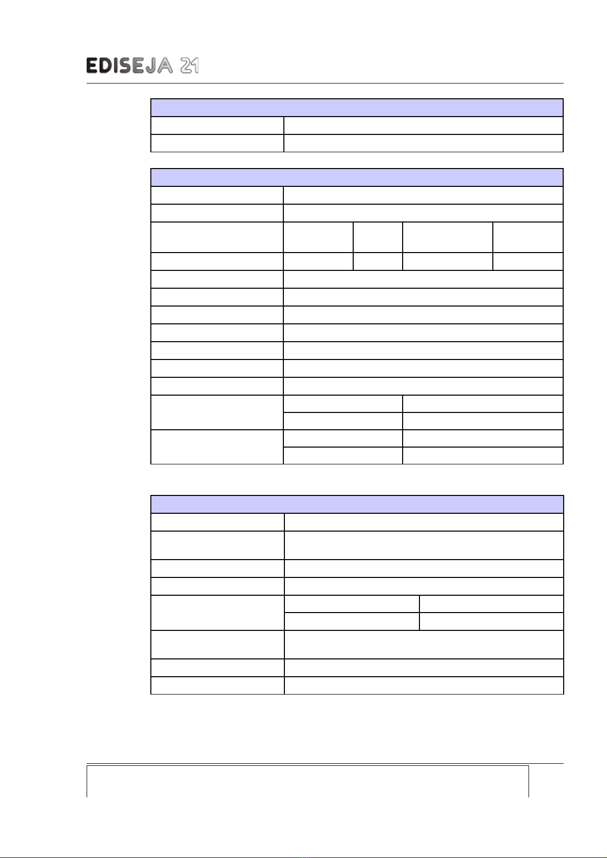
6 TECHNICAL DATA
Power supply
Rated voltage DC 110 V-220 V
AC 230 V
Permissible voltage range DC 88 V-370 V
AC 85 V-264 V
Input current max 0,1 A
Frequency range 47 - 63 Hz
oltage dips > 20 ms
Connector type screw type „MSTB“ Phoenix 2pin
Wire crossection 0,5 – 2,5 mm2
oltage dips 20 ms
Connector type screw type „MSTB“ Phoenix 2pin
Power Supply Wire
crossection 0,5 – 2,5 mm2
type single or stranded wire
voltage rating 500 V
colour see valid standard
Ground wire crossection Cu, 2,5 mm2
colour see valid standard
Communication ports RS232 (interface 2)
Type RS232
Direction full duplex
Speed up to 115,2 kbit/s
Distance up to 15 m
Isolation 500 V DC
Connector type DB9 male
Lines support Rx, Tx
Communication ports - RS485 (interface 5)
Type RS485
Direction half duplex
Speed up to 115,2 kbit/s
Distance up to 1200 m
Page: Device: Document: Code: Date:
12 PEU 016 User manual PEUMU016 17.08.2020
PEU 016 - USB to 16x Serial Port Extender Unit
Communication ports - RS485 (interface 5)
Isolation 500 V DC
Connector type DB9 female
Communication ports - Multimode Fiber Optic (interface 6, 6N, 7 & 7N)
Type multimode fiber optic
Wave lenght 820 nm
Fiber size 50/125 μm 62,5/125
μm
100/140 μm 200 μm HCS
Distance (approx.) 600 m 2000 m 1800 m
Optical output power -18 dB
Reciver sensitivity -24 dB
Laser class ( EC 60825-1)
Direction full duplex
Speed up to 115,2 kbit/s
Input 1 receiver (grey connector)
Output 1 transmitter (white connector)
Logic* interface 6 & 7 positive - light OFF in idle state
interface 6N & 7N negative - light ON in idle state
Connector type interface 6 & 6N ST
interface 7 & 7N SMA
*Logic can be changed by switch on each fiber optic port inside the device.
Other data
Weight up to 1,3 kg
Dimensions (W) 19" rack, (H) 1U (44 mm), (D) 115mm or 87 mm+
connectors
Temperature range 0 °C to +55 °C
Humidity operating up to 95 % (noncondensing)
Enclosure Material inox
P 40
Mount type 19" rack mount
or surface mount with 4x M6 screws
Class
Overvoltage category
Device: Document: Code: Date: Page:
PEU 016 User manual PEUMU016 17.08.2020 13

PEU 016 - USB to 16x Serial Port Extender Unit
7 DIMENSIONS
19" rack holding bracket position can be changed by the user. See chapter „ nstallation“.
The prescribed bending radius of the optical fibre cables must be observed so this type of
enclosure ensures additional depth between front side of PEU 016 and cabinet door. Bend
USB cable holder if it is still too long.
Page: Device: Document: Code: Date:
14 PEU 016 User manual PEUMU016 17.08.2020
Picture 7: Dimen ion front ide
Picture 8: Dimen ion top ide - 19" rack mount deepened for 35 mm
Picture 9: Dimen ion top ide - normal 19" rack mount

PEU 016 - USB to 16x Serial Port Extender Unit
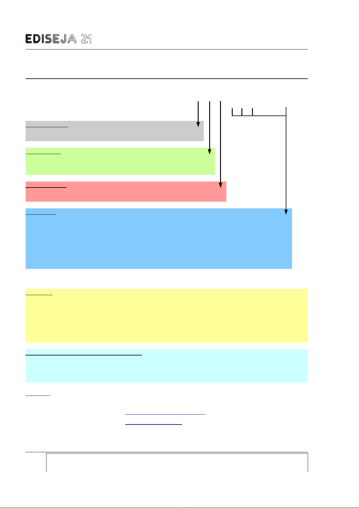
8 ORDERING
ORDER NG NUMBER POS T ON: 1 2 3 4 5 6 ............. 19
ORDERING NUMBER: PEU 016 / c . c . c . c . c . c . ........ . c
NTERFACE NUMBER POS T ON: 1 2 3 ........... 16
Power supply :
110 V-220 V DC, 230 V AC .................................................... 5
Master port:
USB ............................................................................................... U
10/100 Base-Tx (ethernet) ............................................................ E
Power supply:
Rserved for future use: ........................................................................ x
Interfaces: (number of all interfaces in PEU 016 is up to 16!)
None .................................................................................................................. N or leave empty
RS232 isolated, Rx & Tx support, DB9M connector ................................................................... 2
RS485 isolated, half duplex, DB9F connector ............................................................................ 5
Multimode fiber optic (820 nm) ST connector, pos. logic* (signal -> light ON) ........................... 6
Multimode fiber optic (820 nm) ST connector, neg. logic* (signal -> light OFF) ....................... 6N
Multimode fiber optic (820 nm) SMA connector, pos. logic* (signal -> light ON) ........................ 7
Multimode fiber optic (820 nm) SMA connector, neg. logic* (signal -> light OFF) ................... 7N
* User can set fiber optic logic by opening the device and set jumpers accordingly.
Example: PEU 016 / 5 . U . x . 2 . 2 . 5 . 5 . 6 . 6 . 6N . 6N . 6N . 6N . 6N . 6N . 7. 7N . N . N has
- 110 V-220 V DC, 230 V AC power supply
- 2xRS232 with DB9 male connector
- 2xRS485 with DB9 female connector
- 2x MM Fiber Optic ST connector, positive logic
- 6x MM Fiber Optic ST connector, negative logic
- 1x MM Fiber Optic SMA connector, positive logic
- 1x MM Fiber Optic SMA connector, negative logic
Additional accessories (order if needed):
- power supply cable with „schuko“ plug for PEU 016 power supply, 2 m
- RS232 cable to user's device (state the connector & lenght, up to 15 m)
- fiber optic cables (state the connector type & lenght)
- D N 35 holder (2 pcs) + screws (4 pcs)
Contact:
Ediseja 21 d.o.o. Tel: 00 386 51 643 411
Stegne 21C grega.flander@ediseja21.com
1000 Ljubljana www.ediseja21.com
Slovenia – EU
Page: Device: Document: Code: Date:
16 PEU 016 User manual PEUMU016 17.08.2020
Other manuals for PEU 016
1
Table of contents
Other Ediseja 21 Extender manuals


