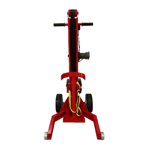
EDMA EDMAPLAC MEGA Instruction Manual

Ref. 267455
BOARD LIFTER
INSTRUCTION AND SECURITY
MANUAL
• Respect the safety instructions in order to avoid injuries or damages on surrounding elements.
• Follow the operating instructions to avoid damaging the tool.
READ THIS MANUAL CAREFULLY BEFORE THE FIRST USE
HANDLE
STEERING WHEEL
POWER DRILL
SUPPORT BASE
MAIN BRAKE LEVER
HANDLE TO ANGLE
THE TOP RACK
WOODEN PLATFORM
Reference : 267455
Maximum loading weight : 80 kg (175 lbs)
Maximum board dimensions : 1,20 x 6.00 m (3,94 x 19,69 Ft)
Minimum board dimensions : 0.15 x 0.60 m (0.49 x 1.97 Ft)
Maximum height with extension part : 4,50 m (14,76 Ft)
Maximum height without extension part : 3,50 m (11,48 Ft)
Minimum height : 161 cm (5,28 Ft)
Maximum vertical lifting height with 2,50 m (8,2 Ft) height board :5,75 m (18,86 Ft)
Board loading height : 80 cm (2,62 Ft) without extension
Minimum width in moving/storage position : 63 cm (243/4”)
Total gross weight: 68.5 kg (151 lbs)
SPARE PARTS
WEAR PARTS
SPECIFICATIONS
- Ref 526732 - Hex bit for using with power drill
- Ref 526761 - Steering wheel central screw
- Ref 526735 - Top rack retractable stopper
- Ref 526756 - Steering wheel
- Ref 526740 - Steering wheel handle
- Ref 526746 - Main brake lever
- Ref 526747- Removable pin
- Ref 526741 - Balance bar with wheels
- Ref 526742 - Power drill support base
- Ref 526737 - Middle foot
- Ref 526744 - Side foot with brake
- Ref 526743 - Side foot without brake
- Ref 526763 - Top rack
- Ref 526764 - Right arm
- Ref 526765 - Left arm
- Ref 526766 - T-arm tube
- Ref 526757 - Extension tube
- Ref 526758 - Internal tube
- Ref 526736 - Wooden platform
- Ref 526754 - 43 mm (13/4’’) screw + nut
- Ref 526753 - 58 mm (21/4’’) screw + nut
- Ref 526751 - 68 mm (25/8’’) screw + nut
- Ref 526750 - 78 mm (31/8’’) screw + nut
- Ref 526755 - Nut
Ref 526730 - Brake lining
Ref 526731 - Metallic cable
Ref 526733 - Wheel with brake
Ref 526734 - Wheel without brake
SAFETY BRAKE
LEVER
REMOVABLE
PIN
CLAMPING
SCREW

NECESSARY TOOLS : 13 mm (1/2”) flat wrench, 6 mm (1/4”) hex wrench
HORIZONTAL CEILING SETTING
AND SLOPING CEILING
12
VERTICAL SETTING STORAGE/MOVING POSITION
INSTRUCTION AND
SECURITY MANUAL
MAJ - 05/18
EDMAPLAC MEGA ASSEMBLY INSTRUCTIONS
Fix the balance bar with wheels to the main
body with the two 78 mm (31/8’’) screws and nuts.
Use a 13 mm (1/2”) at wrench and a 6 mm (1/4”)
hex wrench.
Fix the lateral and central feet to
the base frame with the six 58 mm
(21/4’’) screws and nuts. Use a 13
mm (1/2”) at wrench and a 6 mm
(1/4”) hex wrench.
Position the side feet with brake
on the same side than the security
and main brake levers.
The central foot is the shortest
foot. The central foot nuts have
to be rmly tightened because it
doesn’t rotate like the side feet.
Open the 2 side feet and insert the removable pin in the base frame hole following the selected conguration.
11 nuts
Middle foot
Support base for
power drill
Main body
Top rack
T-Arms tubes
Arms
Integrated extension
Side feet
Two 43 mm (13/4’’) screws
Six 58 mm (21/4’’)screws
One 68 mm (25/8’’) screw
Two 78 mm (31/8’’) screws
Balance bar wheels
3
Ref. 267455
Wooden platform
The top rack must be in low position while changing the feet position.
®

INSTRUCTION AND
SECURITY MANUAL
MAJ - 05/18
Insert the 1 m (3,28 Ft) extension in the frame and lock it in the selected hole with the
removable pin.
The extension has 3 different height positions : 3,50 m (11,48 Ft), 4 m (13,12 Ft) and
4,50 m (14,76 Ft).
Insert the top rack in the extension base and
x it with the 68 mm (25/8’’)screw and nut.
Assemble the arms with
the two 43 mm (13/4’’)
screws and nuts, using a
13 mm (1/2”) at wrench
and a 6 mm (1/4”) hex
wrench. Make the arms
marks match :
R with R and L with L.
Insert the arms in the top rack according to the position
selected. When you are in front of the steering wheel, put the
R arm on your right and the L arm on your left. The retractable
pins must be locked in the corresponding holes.
Follow the marks on the arms to select the appropriate width :
Mark 1 (without T-arms tubes) – Distance between axes : 2.3 m (7.55 Ft).
Mark 2 (with T-arms tubes) – Distance between axes : 2.8 m (9.19 Ft).
Mark 3 (with T-arms tubes) – Distance between axes : 3.6 m (11.81 Ft).
Mark 4 (with T-arms tubes) – Distance between axes : 4.3 m (14.11 Ft).
Mark 5 (with T-arms tubes) – Distance between axes : 4.88 m (16.01 Ft).
There are 5 different positions to adjust the arms width.
Distance between axes
Fix the power drill support base to the main body with the 2
provided screws and tighten the wing nuts to lock the support
base.
3,50 m (11,48 Ft) 4 m (13,12 Ft) 4,50 m (14,76 Ft)
4
5
6
7
8
Ref. 267455

INSTRUCTION AND
SECURITY MANUAL
MAJ - 05/18
OPERATING INSTRUCTIONS
1Lift the latch to unlock the top rack and tilt it completely.
Insert the arms in the tube according to the selected setting, the retractable pin must be locked in the hole.
Block the 2 wheel brakes, then load the board.
Pull the handle to position the board on the chosen conguration.
2
3
4
Ref. 267455

INSTRUCTION AND
SECURITY MANUAL
MAJ - 05/18
OPERATING INSTRUCTIONS
Ref. 267455
5Unlock the 2 wheel brakes and turn the steering wheel while pushing
the main brake lever to lift the board.
Once the board touches the ceiling, position
the board perfectly and lock the wheel
brakes while screwing the board.
Push the brake lever while lifting the safety brake latch, to lower the top rack. If you have to lower the top rack
loaded, pay attention to control the descent by pushing slightly on the main brake lever.
In case of a main brake default, release immediately the safety brake lever in order to stop the descent right
away.
6
7

INSTRUCTION AND
SECURITY MANUAL
MAJ - 05/18
LOADING CONFIGURATIONS
HORIZONTAL CEILING - SLOPING CEILING AND HORIZONTAL WALL SETTING
Open the feet as much as possible and insert
each removable pin in the 3rd hole of the
base frame.
Insert the arms in the
horizontal tubes, the
retractable pin must be
locked in the selected hole.
Turn the steering wheel while pushing the main brake lever to lift the board up to the ceiling.
Once the board loaded(*), position the EDMAPLAC® MEGA along the wall. Pull out the removable pin from the
top rack in order to angle the board completely, while pushing the EDMAPLAC® MEGA along the wall thanks to
the top rack handle. Lock the 2 wheel brakes. We advise to not exceed a loading weight of 32 kg (71 lbs) for
this setting.
(*)Always ensure that board is correctly centered on the panel lifter head.
Once the board loaded(*), pull the
top rack handle to put the board in
horizontal position.
Position the panel lifter with the
steering wheel in front of the wall
to lift the board along the wall.
(*)Always ensure that board is
correctly centered on the panel
lifter head.
Once the board loaded(*),
pull out the removable pin to
unlock the top rack, then pull
the handle to angle the board.
Insert the removable pin in the
sloping ceiling position hole (45°
position). The top rack position is
adjusted according to the ceiling
angle while the board is touching
the ceiling.
(*)Always ensure that board is
correctly centered on the panel
lifter head.
1
2
3a
3b
4
5
CEILING SETTING
HORIZONTAL SLOPING CEILING
HORIZONTAL WALL SETTING
Ref. 267455

INSTRUCTION AND
SECURITY MANUAL
MAJ - 05/18
LOADING CONFIGURATIONS
VERTICAL LIFTING AND VERTICAL SLOPING CEILING SETTING
Insert the arms in the vertical tubes, the
retractable pin must be locked in the
selected hole according to the board
dimensions.
- 1st hole for vertical sloping ceiling
- 2nd hole (with “vertical position”
marking) for vertical lifting
Once the board loaded(*), pull out the
removable pin to unlock the top rack,
then pull the handle to angle the
board and insert the removable pin in
the sloping ceiling position hole (45°
position).
The top rack position is adjusted
according to the ceiling angle while
the board is touching the ceiling.
(*)Always ensure that board is
correctly centered on the panel lifter
head.
Once the board loaded(*), position the
EDMAPLAC® MEGA along the vertical
wall. Pull out the removable pins from
the 2 lateral feet and open them up to
the 2nd hole of the frame base. Insert
the removable pins to lock the feet. Pull
out the removable pin from the top rack
in order to angle the board completely
on vertical position, while pushing the
EDMAPLAC® MEGA along the wall thanks
to the top rack handle. Lock the 2 wheel
brakes.
(*)Always ensure that board is correctly
centered on the panel lifter head.
Turn the steering wheel while
pushing the main brake lever to
lift the board.
1
2a
2b
3
VERTICAL SLOPING CEILING
VERTICAL lifting
Ref. 267455

INSTRUCTION AND
SECURITY MANUAL
MAJ - 05/18
AUTOMATIC USE ASSISTED BY POWER DRILL
1First of all, you must use the power drill support base for safety reason. Then, set up the EDMAPLAC®MEGA
according to the selected setting conguration.
Insert the hex bit in the
power drill chuck
Adjust the power drill
support base according to
the power drill dimensions.
Insert the hex bit xed to the power drill, in the hex hole located in the
middle of the steering wheel. Turn the power drill to block it against the
power drill support base. Set the power drill on “maximum torque - low
speed”, rotating on clockwise direction.
Pull the power drill trigger to lift the board.
To lower the top rack, remove the power drill rst, then push the main brake lever while lifting
up the safety brake latch.
23
4
5
6
Ref. 267455
POWER DRILL MINI 14.4 VOLTS - 3 Ah
powerdrill
DIRECTIONOF
ROTATION
MAXIMUM TORQUE
LOW SPEED

INSTRUCTION AND
SECURITY MANUAL
MAJ - 05/18
SAFETY INSTRUCTIONS
PRECAUTIONS BEFORE USE
• Make sure all the parts are perfectly well assembled
• Make sure all the nuts are well tight and the removable pins are in position.
• Remove the dust from the gear as well as the rack and pinion.
• Make sure the retractable pins are well locked in their holes.
• Before each use, make a general operational checking.
• Make sure the cable is in good condition. Do not hesitate to change it as soon as the tiniest imperfection
is visible : crushing, pinching, wire breaking.
• Make sure the main brake is in good condition and well adjusted. Once the board lifted at the required
height, it has to stay in position when the safety brake is unlocked. If the top rack goes down, tighten the
main brake by turning the knurled nut clockwise direction.
General safety warnings
• This tool is exclusively dedicated to the plasterboard setting.
• The maximum loading weight is 80 kg (175 lbs). Do not exceed the maximum weight in order to avoid a premature wear.
• Do not use EDMAPLAC®MEGA as a freight elevator or person elevator.
• Do not grease or oil the rack and pinion as well as the gear.
• The top rack must be in low position while changing the feet position.
• Do not use the tool carrier wooden board as a working platform. Use a stepladder or a regulatory working platform to
screw the board onto the ceiling.
• Do not hinder the wheels while using. It may cause a failover of the device.
• Do not clutter up the working area in order to move the EDMAPLAC®MEGA easier.
• Do not put your hand through the steering wheel while the top rack is lowering. It may cause hand or nger injuries.
• Do not let children use the EDMAPLAC®MEGA.
• Do not erase the EDMAPLAC®MEGA warning markings.
• Any modications on the tool are not allowed.
• Once the board lifted at the required height, it has to stay in position when the safety brake is unlocked. If the board goes
down, tighten the main brake by turning the knurled nut clockwise direction. If the board is heavier than a standard board
(more than 25 kg), turn the knurled nut clockwise direction to increase the spring power. If the board still goes down even
with the knurled nut at its tightest, change the brake lining.
• Use the EDMAPLAC® MEGA on a rm and stable surface which can support the weight of the tool and plasterboard.
• Lock the 2 wheel brakes while lifting a board.
• The user has to ensure his own safety as well as the safety of the other people around the EDMAPLAC®MEGA.
• In order to avoid collision with the top rack during its descent, use the main brake to regulate the speed. In case of a main
brake default, release immediately the safety brake lever in order to stop the descent right away.
• Wearing a helmet : follow the current legislation
• Have the device checked regularly by a control agency (decree of 1st march 2004).
Ref. 267455

INSTRUCTION AND
SECURITY MANUAL
MAJ - 05/18
CABLE REPLACEMENT
a
b
1
1
35
3
2
2
4
45
Unscrew the axis maintaining the pulley and remove
it with a 17 mm (11/16”) at wrench and an 8 mm
(5/16”) hex wrench.
Put the axis through the cable loop to x it to the
internal tube.
Remove the pulley. Unscrew the screw from the
main body with a 5 mm (3/16”)
hex wrench, in order to
remove the cable completely.
Put the pulley back to its location.
Pull the internal tube out.
Fix the opposite cable loop to the main body with
the provided screw.
Unscrew
the nut from
the axis
maintaining
the cable to
the main body.
Use a 10 mm
(3/8”) at
wrench and a 5
mm (3/16”) hex
wrench.
Put the principal tube back in the main
body.
Put the axis maintaining the pulley back
and tighten the nut on the axis with a
17 mm (11/16”) at wrench and an 8 mm
(5/16”) hex wrench.
For this step, the internal tube must not
be completely inserted in the frame.
NECESSARY TOOLS : 10 (3/8”) and 17 mm (11/16”) flat wrench, 5 (3/16”) and 8 mm (5/16”) hex wrench
WITHDRAWAL OF USED CABLE
NEW CABLE INSTALLATION
Ref. 267455

INSTRUCTION AND
SECURITY MANUAL
MAJ - 05/18
BRAKE LINING REPLACEMENT
1
1
2
3
4
3
2
4
Unscrew the central axis of the steering
wheel with a 6 mm (1/4”) hex wrench.
Insert the brake lining in its location.
Put the steering wheel on the main axis and make sure that the small key is in its location.
Replace the spring.
Screw the steering wheel central axis.
Pull the steering wheel to remove it from the
axis. Be careful not to lose the small key while
pulling the steering wheel.
Remove the spring by lifting the main
brake lever.
Pull the brake lining to remove it from its
location.
NECESSARY TOOLS : 6 mm (1/4”) hex wrench
WITHDRAWAL OF BRAKE LINING
NEW BRAKE LINING INSTALLATION
a
b
Ref. 267455

EDMA S.A.S
TECHNOPARC EPSILON 1
616, Rue Isaac Newton
83700 SAINT-RAPHAËL
FRANCE
Tel. : +33 (0)4 94 44 70 70
Fax : +33 (0)4 94 44 70 71
Internet : www.edma.fr
* 1 year warranty in case of manufacturing defects under normal use. This warranty does not take into account wear parts : brake lining, cable,
wheels, top rack retractable stops.
YEAR
In conformity with European directive ‘‘MACHINERY’’ 2006/42/CE.
Approved by the VERITAS conformity report # 628 8214-1.
R
e
p
o
r
t
N
o
6
2
8
8
2
1
4
-
1
A
P
P
R
O
V
E
D
B
Y
V
E
R
I
T
A
S
This manual suits for next models
1
Table of contents
Other EDMA Lifting System manuals
Popular Lifting System manuals by other brands

Mortuary Lift
Mortuary Lift ULTIMATE 1000 Installation Suggestions
Granberg
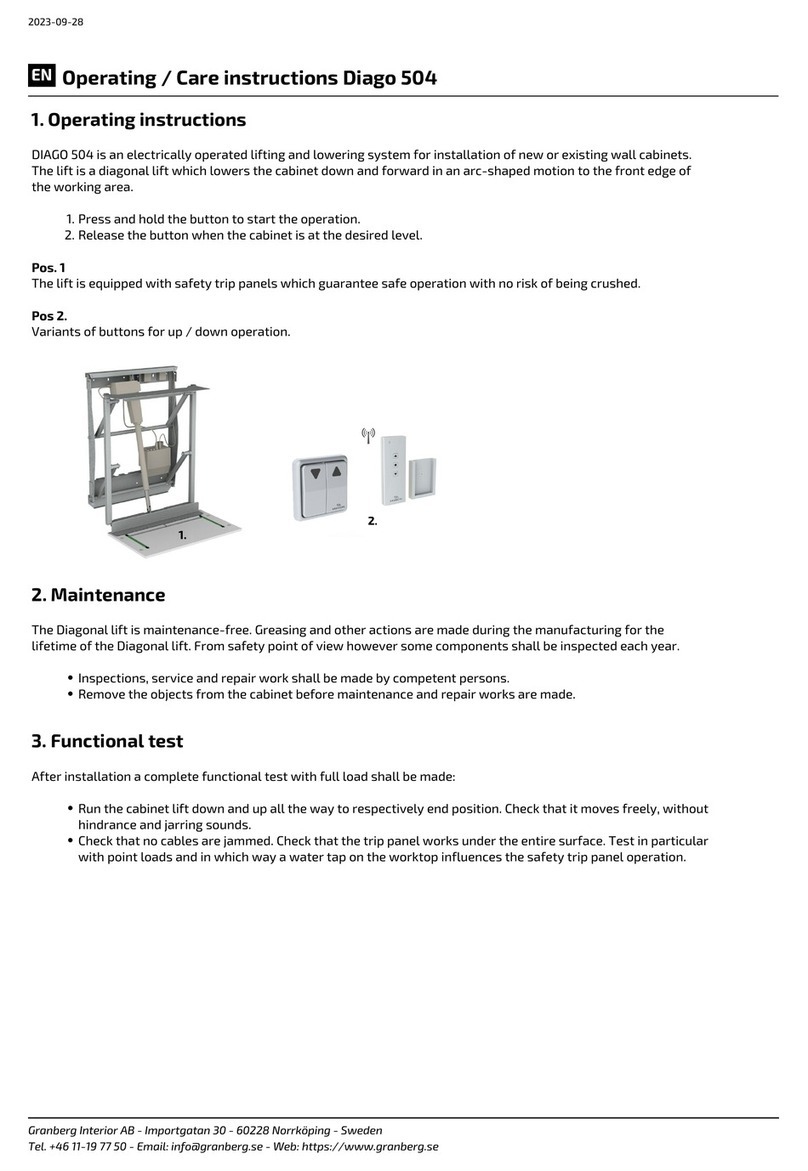
Granberg Diago 504 Operating and care instructions

Southern States
Southern States EV installation instructions

Sealey
Sealey MC454E instructions
Porta-Dock
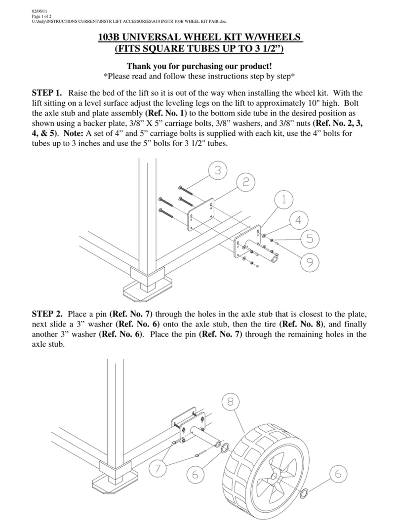
Porta-Dock 103B quick guide
TECHNOLIFT
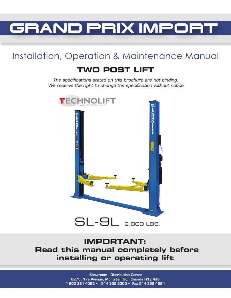
TECHNOLIFT SL-9L Installation, operation & maintenance manual
ATN
ATN Zebra 12 Operator’s and Safety Handbook
ThyssenKrupp
ThyssenKrupp Flow2 user manual

ACCO Brands
ACCO Brands ACCOLIFT series instruction manual
Halfen
Halfen DEHA KKT-U Assembly instructions
CHIEF
CHIEF CM2L40 installation instructions

Terex
Terex Genie Lift Tools Expo Installer Z-45/25 Operator's manual supplement

