EDN CMP375 Series User manual
CMP375 Series
CMP375 Series – Rev. 1.1, Issue 11/07 Page 1 of 12
User's Manual
EDN GR UP S.r.l. Via Mazzini, 10/12 – 20032 – CORMANO (M ) TALY – TEL. +39 02 66305120 FAX +39 02 61540938
C NSULT TECHNICAL SALES F R M RE DETAILED DATA SHEETS R TECHNICAL MANUAL
e-mail: [email protected] web.site: www.edngroup.com
CMP375 Series
7KW Sealed, Single-Phase, N-B ARD Chargers
for Electric Vehicles (EV, PHEV)
User's MANUAL

CMP375 Series
CMP375 Series – Rev. 1.1, Issue 11/07 Page 2 of 12
User's Manual
Table of contents
SAFETY INF RMATI N................................................................................................................................. 3
FUNCTI NAL DESCRIPTI N......................................................................................................................... 4
VERVIEW................................................................................................................................................. 4
PERATI N M DE Mode......................................................................................................................... 5
CAN Messages...................................................................................................................................... 5
SAE J1772............................................................................................................................................. 5
P WER LIMITER................................................................................................................................... 5
CHARGER STATE Definition............................................................................................................... 6
FAN UTPUT (V03).................................................................................................................................... 6
BMS UTPUT (V02)................................................................................................................................... 6
TECHNICAL SPECIFICATI N........................................................................................................................ 7
Input Data.............................................................................................................................................. 7
General Data......................................................................................................................................... 7
utputs Data......................................................................................................................................... 7
Standard Applied.................................................................................................................................. 7
Mechanical Data.................................................................................................................................... 7
C NNECT RS SPECIFICATI N.................................................................................................................... 8
C NTR L PINS SPECIFICATI N........................................................................................................ 9
GR UND (KL31).............................................................................................................................. 9
CAN BUS.......................................................................................................................................... 9
ENABLE............................................................................................................................................ 9
ALARM, ............................................................................................................................................ 9
LINE PRESENT, .............................................................................................................................. 9
CHARGER C NNECTED, D02........................................................................................................ 9
IGNITI N RUN (KL31).................................................................................................................... 10
LV ALWAYS H T (KL30)............................................................................................................... 10
C NTR L PIL T........................................................................................................................... 10
PR XIMITY DETECTI N............................................................................................................... 10
MECHANICAL DATA..................................................................................................................................... 11
REPLACEABLE PARTS................................................................................................................................ 12
WARRANTY................................................................................................................................................... 12
EDN GR UP S.r.l. Via Mazzini, 10/12 – 20032 – CORMANO (M ) TALY – TEL. +39 02 66305120 FAX +39 02 61540938
C NSULT TECHNICAL SALES F R M RE DETAILED DATA SHEETS R TECHNICAL MANUAL
e-mail: [email protected] web.site: www.edngroup.com
CMP375 Series
CMP375 Series – Rev. 1.1, Issue 11/07 Page 3 of 12
User's Manual
SAFETY INF RMATI N
Dear Customer, for your safety...
•Read carefully the instructions in this manual.
•WARNING - High DC voltages can e dangerous and lethal.
Failure to install or operate in accordance with these
instructions may result in damage to the charger or injury to
the operator.
•WARNING - The charger cannot operate without a safety
ground connection. The use of a Ground Fault Interruption
circuit is recommended.
•WARNING - Do not attempt to open the charger. There is risk
of electric shock even if the charger is unplugged. No user
servicea le components inside.
•Keep the charger from heating sources.
•The operating charger has hot surfaces. Touching the hot
charger can lead to injuries and urnings.
•If safe operation cannot e longer ensured, STOP and secure
it against operation.
•If the charger failure or malfunction may cause personal injury
or material damage, use additional safety and operational
measures. Such as limit switches, guards, etc.
•Make sure that the attery pack and the mains power line
characteristics are in the correct range with respect to the
charger's technical data.
•Charger should not e installed in a location which restricts
airflow to the unit.
•Failure to install and use the charger in accordance with this
manual and data may impair the protection provided y the
charger and void the manufacturer's warranty.
•Have the charger installed and made operational y a skilled
professional.
•Never disconnect the attery plug out of unit without reaking
the attery pack connection eforehand.
•Remove the mains plug from the mains outlet efore reaking
the attery pack circuit.
•Always disconnect mains power line after charging and
generally when the unit is not in use.
EDN GR UP S.r.l. Via Mazzini, 10/12 – 20032 – CORMANO (M ) TALY – TEL. +39 02 66305120 FAX +39 02 61540938
C NSULT TECHNICAL SALES F R M RE DETAILED DATA SHEETS R TECHNICAL MANUAL
e-mail: [email protected] web.site: www.edngroup.com

CMP375 Series
CMP375 Series – Rev. 1.1, Issue 11/07 Page 4 of 12
User's Manual
FUNCTI NAL DESCRIPTI N
VERVIEW
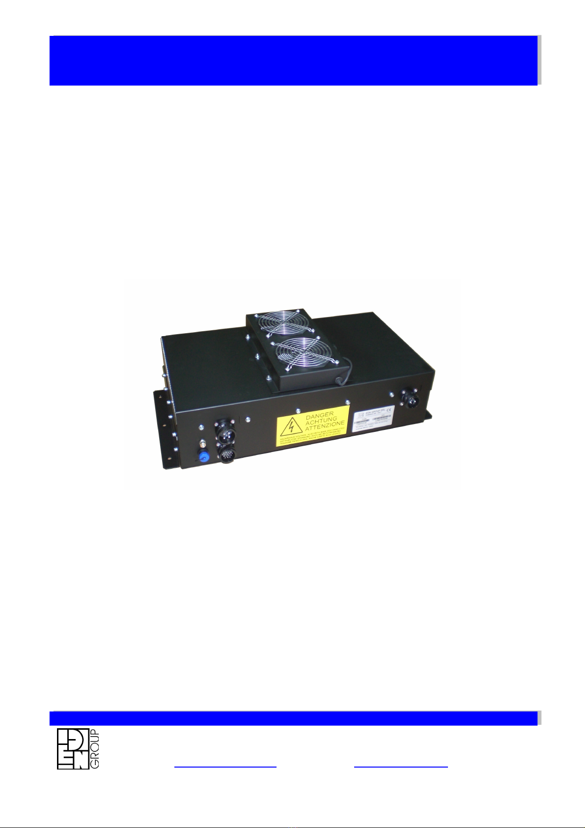
CMP375 Series is a very versatile, safe and high-tech charger for On-
Board electric vehicle (EV, PHEV) applications.
The characteristics of a CMP375 ena le the safe and powerful
charging of Lithium attery pack.
The unit contains an electrically isolated high frequency AC/DC
converter with active Power Factor Correction circuitry that efficiently
transforms the mains AC line into a fully controlled DC power for
charging the attery pack.
The control signals, isolated from attery pack (SELV), assure for
maximum personal protection and they are in compliance with the
applica le Standards.
Moreover, ena le a simple connection with the charging infrastructure
(BMS, VMU, Power Station).
An high protection degree (IP55 for the fan and IP67 for the ca inet)
com ined with a rugged design gives an exceptional usa ility in every
situation and automotive environment.
An easy CAN setup permits connecting the units in parallel to realize
stacka le and redundant solution (up to 4 unit).
CMP375 series meets the safety and EMC requirements esta lished
y the CE mark and ECE regulation.
EDN GR UP S.r.l. Via Mazzini, 10/12 – 20032 – CORMANO (M ) TALY – TEL. +39 02 66305120 FAX +39 02 61540938
C NSULT TECHNICAL SALES F R M RE DETAILED DATA SHEETS R TECHNICAL MANUAL
e-mail: [email protected] web.site: www.edngroup.com
CMP375 Series
CMP375 Series – Rev. 1.1, Issue 11/07 Page 5 of 12
User's Manual
PERATI N M DE
The charger is controlled y an external Battery Management System
(BMS) or Vehicle Management Unit (VMU) over CAN V2.0B (see
MT3594 and specific CAN manual ).
CAN Messages
A fully customized V2.0B interface (STD/EXT frame, messages, aud
rate, SAE J1939) is availa le on request.
Overview – std CAN messages:
Messages contents
Control Iout & Vout reference value, control its
Status Status of charger
Values Actual Iout & Vout values of the charger
Temperatures Internal temperature
Errors Errors & Warning
See MT3594 for details
SAE J1772
When set, allows the charger to fully couple with SAE J1772 Power
Station (EVSE SAE J1772 compliant, level 1 and 2). The charger
automatically turn on and off when SAE J1772 signal is present and
valid. A charger SLEEP mode (Imax = 15 mA drawn from KL30) is
activated when the Proximity signal is lost for more that 1 minute. The
unit wakes up when Proximity or Ignition Run is present.
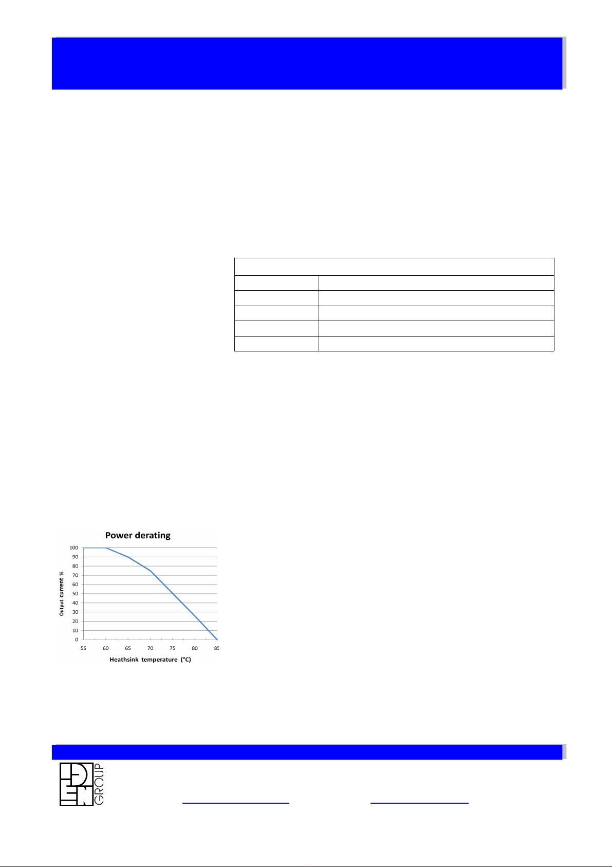
POWER LIMITER
The charger, in order to ensure safe operation, controls: output
current, output voltage, power and temperatures. The charging output
power is limited or stopped if some critical parameters limits is
reached.
In particular, in order to prevent the charger overheating, the output
current is reduced y the heatsink's (+60°C...+85°C), magnetic and
internal temperatures according to the chart.
Higher heatsink's temperature produce the unit to switch off.
EDN GR UP S.r.l. Via Mazzini, 10/12 – 20032 – CORMANO (M ) TALY – TEL. +39 02 66305120 FAX +39 02 61540938
C NSULT TECHNICAL SALES F R M RE DETAILED DATA SHEETS R TECHNICAL MANUAL
e-mail: [email protected] web.site: www.edngroup.com

CMP375 Series
CMP375 Series – Rev. 1.1, Issue 11/07 Page 6 of 12
User's Manual
CHARGER STATE Definition
The Charger has the following states:
•NOT CONNECTED – no connection from EVSE to Charge
Coupler is detected (no valid Proximity Detection signal, no
valid Control Pilot signal indicating connection, no valid AC
power is present).
•CONNECTED STAND-BY – connection detected y Proximity
detection signal or the Control Pilot or AC power on the inlet
connector (J1) ut Ena le signals (CAN, HW) are not present.
•CONNECTED CHARGING – the charger provides HV DC
output power.
FAN UTPUT (V03)
The charger has an electrically floating output +24V/1A (V03) used to
supply the FAN assem ly.
The FAN assem ly is supplied directly y the FAN+ and FAN- outputs.
The fans low only when the charger is working and the speed
depends y the charger's output current level.
BMS UTPUT (V02)
The charger provide an +12V/0.1A (V02) output that can e used to
wake up the the BMS unit.
EDN GR UP S.r.l. Via Mazzini, 10/12 – 20032 – CORMANO (M ) TALY – TEL. +39 02 66305120 FAX +39 02 61540938
C NSULT TECHNICAL SALES F R M RE DETAILED DATA SHEETS R TECHNICAL MANUAL
e-mail: [email protected] web.site: www.edngroup.com

CMP375 Series
CMP375 Series – Rev. 1.1, Issue 11/07 Page 7 of 12
User's Manual
EDN GR UP S.r.l. Via Mazzini, 10/12 – 20032 – CORMANO (M ) TALY – TEL. +39 02 66305120 FAX +39 02 61540938
C NSULT TECHNICAL SALES F R M RE DETAILED DATA SHEETS R TECHNICAL MANUAL
e-mail: [email protected] web.site: www.edngroup.com
TECHNICAL SPECIFICATI N
Input Data Reduced Power Full Power Units
Input Voltage Range 100... 185 … 274 Vac
Line Frequency 47...63 Hz
Input Current (Max value is SAE J1772 controlled ) 32 32 Aac
A sor ed Maximum Apparent Power 3840 @ 120Vac, 32Aac 7800 VA
Power Factor > 0,98
General Data Units
Protections Output over-voltage
Output over-current
Output polarity reversal
Input over-voltage
Am ient Temperature - Operating -40...+85 °C
Am ient Temperature - Full performance -25...+60
Power de-rating -4%/°C (with cold plate temperature from +60°C to +85°C)
Heat Dissipation IP55 FAN cooling
Protection Degree (enclosure) IP67
Efficiency > 90 @ from 25% to Max load %
Control interface CAN v2.0B (K it/s, STD/EXT frame and ID's adapta le)
Remote alarm Relay contacts potential free (“OR” of thermal protection, over-voltage, etc.)
Mains presence Relay contacts potential free
utputs Data Reduced Power Full Power Units
V01 Output Voltage (max) 300...750 Vdc
V01 Voltage Accuracy ± 1
V01 Output Current (max) 4,5 9,5 Adc
V01 Rated Output Power 3400 @ 120Vac, 32Aac 7200 W
V01 Parameters control CAN v2.0B
V02 Output BMS Voltage 12 Vdc
V02 Output BMS Current 0,1 Adc
V03 Output FAN Voltage 24 Vdc
V03 Output FAN Current 1,0 Adc
Standard Applied Units
General Requirements EN 61851-1, EN 61851-21, SAE J1772
EMC – Emission EN61000-3-4, CISPR 14, 16 level A
EMC – Immunity EN61000-4-1, EN61000-4-4, EN61000-4-5, EN61000-4-11, EN61000-4-3
SAFETY EN 60950-1:2002 + A11:2004, ECE regulation 100
Dielectric Withstand Voltage AC Input / P.E.:
AC Input / DC Output:
DC Output V01 / P.E.:
AC Input / SELV:
1500Vac @ 1min.
1500Vac @ 1min.
1000Vdc @ 1min.
4000Vac @ 1min.
Insulation resistance AC Input, DC Output / P.E.: > 10MΩ @ 500Vdc
Earth leakage current < 3.5 mA
Chassis Ground Stud M6
Mechanical Data Units
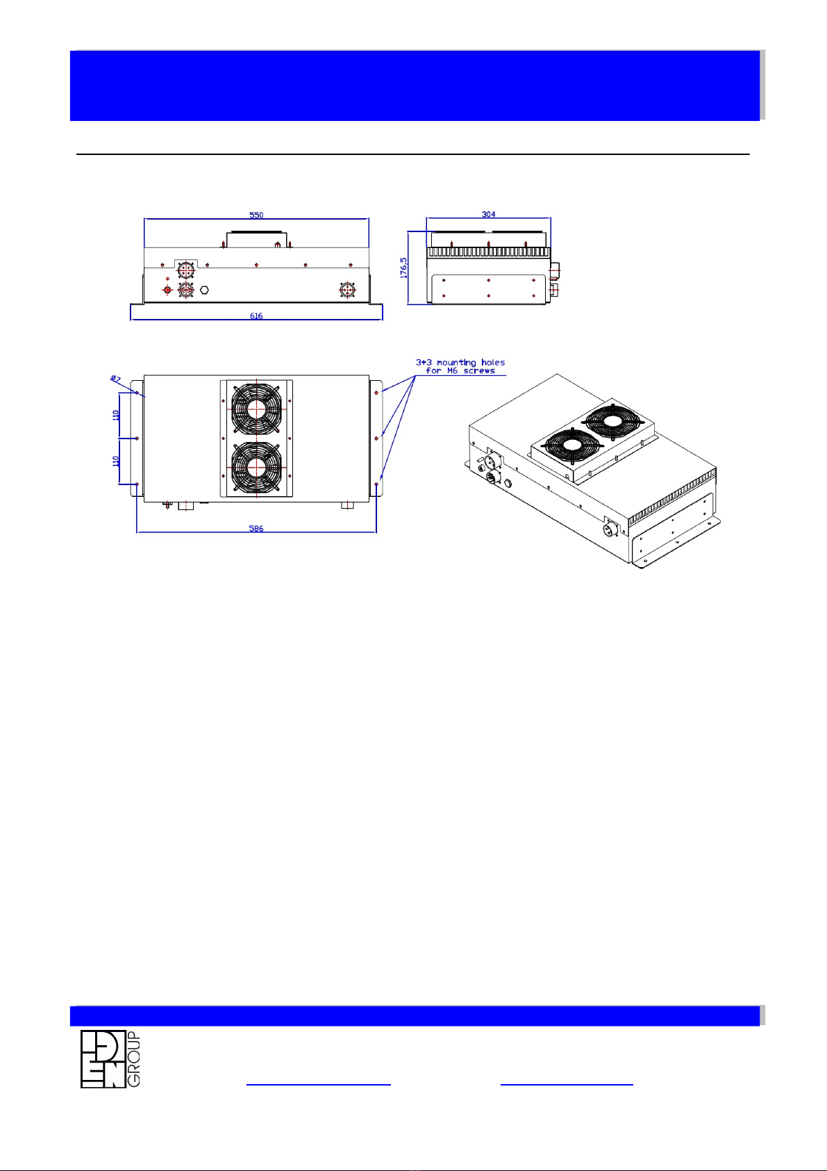
Dimensions: Width x Depth x Height 616 x 304 x 176,5 mm
Weight (ca.) 23 Kg
Case Material Aluminium (Black Polyester Powder Coating)
Case Type Box
I/O Connections AC Input :
V01 Power Output (to attery packs) :
Control signal and Interface :
IP67 MS Circular connectors
IP67 MS Circular connectors
IP67 MS Circular connectors

CMP375 Series
CMP375 Series – Rev. 1.1, Issue 11/07 Page 8 of 12
User's Manual
nector manuf
C NNECT R SPECIFICATI N
CONNECTORS DATA
Id Function Mate connector
J1 Main input connector Brand: VAN-SYSTEM Code: CVB06AC 22-22S CR F
J2 Control I/O connector Brand: VAN-SYSTEM Code: CVB06AC 20-A48S CR F
J3 Power Output connector Brand: VAN-SYSTEM Code: CVB06AC 20-4S CR F
PINS DATA: Main Input (J1) :
PIN Function J1772 AC level 1, 2 conductive coupler
A AC POWER (L1) Mains power *
B CONTROL PILOT Primary control conductor *
C PROXIMITY DETECTION Primary detection conductor to detect presence of charge connector *
D AC POWER (L2, N) Mains power *
* CHASSIS GROUND / POWER HEART (P.E.) CONNECTION - EVSE equipment grounding conductor to EV chassis ground is located on the connectors side of the enclosure
PINS DATA: Control I/O (J2) :
PIN Function
A ALARM Open Drain, active low, 24V, 1A
B LINE PRESENT Open Drain, active low, 24V, 1A
C IGNITION RUN (KL15) 8...16 volts
D CHARGER CONNECTED Open Drain, active low, 24V, 1A
E DO2 (Programma le) Open Drain, active low, 24V, 1A
F FAN- (V03) 24V, 1A
G FAN+ (V03) 24V, 1A
H BMS WAKE-UP (V02) 12V, 0,1A
J CONNECTION CONTROL LOOP (connect to pin T to START) 5V, 5mA
K ENABLE (OPEN = ON) 5V, 5mA
L GROUND (KL31) Connected to Charger Chassis groud stud
M LV Always Hot Power Battery (KL30) 8...16 volts
N CAN LOW 5V, V2.0B
P GROUND (KL31) Connected to Charger Chassis groud stud
R NOT CONNECTED -
S GROUND (KL31) Connected to Charger Chassis groud stud
T CONNECTION CONTROL LOOP (connect to pin J to START) 5V, 5mA
U CAN HIGH 5V, V2.0B
V CAN Shield Connected to Charger Chassis groud stud
PINS DATA: Power Output (J3) :
PIN Function
A INTERLOOK CONNECTION (connect to pin C for START) 5V, 5mA
B NEGATIVE POWER OUTPUT
C INTERLOOK CONNECTION (connect to pin A for START) 5V, 5mA
D POSITIVE POWER OUTPUT
EDN GR UP S.r.l. Via Mazzini, 10/12 – 20032 – CORMANO (M ) TALY – TEL. +39 02 66305120 FAX +39 02 61540938
C NSULT TECHNICAL SALES F R M RE DETAILED DATA SHEETS R TECHNICAL MANUAL
e-mail: [email protected] web.site: www.edngroup.com

CMP375 Series
CMP375 Series – Rev. 1.1, Issue 11/07 Page 9 of 12
User's Manual
C NTR L PINS SPECIFICATI N
GR UND (KL31)
The GROUND signal is directly
connected to the chassis ground
(Vehicle's ground) as showed.
CAN BUS
The CAN interface has the following
characteristics:
•CAN V2.0B,
•Fully isolated from attery
pack potential (SELV)
•No terminating resistor
ENABLE
The Ena le signal puts the charger in
Connected Charging state (DC output
On).
ALARM
LINE PRESENT
CHARGER C NNECTED, D02
Four Open Drain Outputs connect to
GROUND; Imax = 1 amp.
Alarm indicates when a charger's fault
is detected.
Line Present indicates when mains
AC input is more that 80Vac.
Charger Connected signal indicates
when an EVSE Charge Connector is
detected.
EDN GR UP S.r.l. Via Mazzini, 10/12 – 20032 – CORMANO (M ) TALY – TEL. +39 02 66305120 FAX +39 02 61540938
C NSULT TECHNICAL SALES F R M RE DETAILED DATA SHEETS R TECHNICAL MANUAL
e-mail: [email protected] web.site: www.edngroup.com

CMP375 Series
CMP375 Series – Rev. 1.1, Issue 11/07 Page 10 of 12
User's Manual
IGNITI N RUN (KL31)
The Ignition Run signal wakes up the
charger from SLEEP.
LV ALWAYS H T (KL30)
The LV Always Hot input supplies the
charger's logic and permits CAN
communication when AC power is not
present (SAE J1772 fully compliance).
C NTR L PIL T
SAE J1772 Control Pilot compliant
signal.
.
PR XIMITY DETECTI N
SAE J1772 Proximity Detection
compliant signal.
EDN GR UP S.r.l. Via Mazzini, 10/12 – 20032 – CORMANO (M ) TALY – TEL. +39 02 66305120 FAX +39 02 61540938
C NSULT TECHNICAL SALES F R M RE DETAILED DATA SHEETS R TECHNICAL MANUAL
e-mail: [email protected] web.site: www.edngroup.com
CMP375 Series
CMP375 Series – Rev. 1.1, Issue 11/07 Page 11 of 12
User's Manual
EDN GR UP S.r.l. Via Mazzini, 10/12 – 20032 – CORMANO (M ) TALY – TEL. +39 02 66305120 FAX +39 02 61540938
C NSULT TECHNICAL SALES F R M RE DETAILED DATA SHEETS R TECHNICAL MANUAL
e-mail: [email protected] web.site: www.edngroup.com
MECHANICAL DATA

CMP375 Series
CMP375 Series – Rev. 1.1, Issue 11/07 Page 12 of 12
User's Manual
REPLACEABLE PARTS
EDN Code Description
NF10830 Fixing Brackets
NF10840 Top fan assem ly 24V
WARRANTY
CMP375series have a warranty covering defects in materials and
workmanship for a period of 24 months from the date of purchase.
Improper use or handling of the products causes the warranty to e
void.
Technical specification are su ject to change without notice.
Take note that lethal voltages exist around this unit. EDN GROUP
cannot accept any lia ility concerning this danger.
EDN GROUP furthermore do not accept any lia ility for consequential
damages which arose from the use of this device.
WARNING
Take note that careless handling of high DC voltages can e very dangerous and lethal.
So please take time to read the manual and connect the unit properly
and call a skilled professional in any case.
EDN GR UP S.r.l. Via Mazzini, 10/12 – 20032 – CORMANO (M ) TALY – TEL. +39 02 66305120 FAX +39 02 61540938
C NSULT TECHNICAL SALES F R M RE DETAILED DATA SHEETS R TECHNICAL MANUAL
e-mail: [email protected] web.site: www.edngroup.com
Table of contents
Popular Batteries Charger manuals by other brands


IVT
IVT Voltcraft 900011 Instructions for use

Autel Robotics
Autel Robotics EVO Lite Series Guidelines

ABB
ABB HT576033 Operation manual

Steen QOS
Steen QOS SH4934 Instructions for installation and operation

Villager
Villager VCSB 24 S Original instruction manual

cabur
cabur EV EVO Stand Instruction and safety manual


