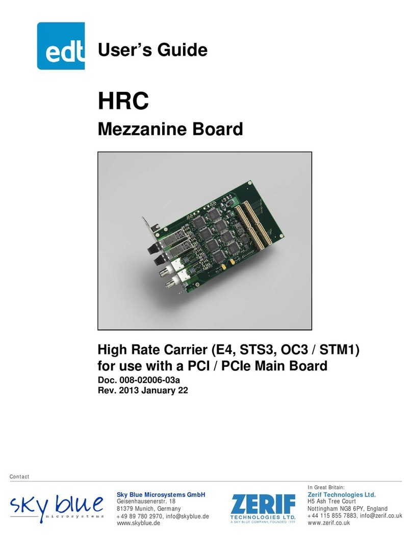
EDT PCIe8g3 S5 Series User manual

User’s Guide
PCIe8g3 S5 Family
PCIe Gen3 x8 boards with
Stratix V FPGA and 10G / 40G ports
Date: 2017 January 04
Rev.: 0001

EDT, Inc. 2
EDT | Engineering Design Team, Inc.
3423 NE John Olsen Ave
Hillsboro, OR 97124
U.S.A.
Tel: +1-503-690-1234 | Toll free (in U.S.A.): 800-435-4320
Fax: +1-503-690-1243
www.edt.com
TM
TM
EDT
and Engineering Design Team
are trademarks of Engineering Design Team, Inc. All other trademarks, service marks,
and copyrights are the property of their respective owners†.
© 1997-2019 Engineering Design Team, Inc. All rights reserved.

EDT, Inc. 3
Terms of Use Agreement
Definitions. This agreement, between Engineering Design Team, Inc. (“Seller”) and the user or distributor (“Buyer”), covers the
use and distribution of the following items provided by Seller: a) the binary and all provided source code for any and all device
drivers, software libraries, utilities, and example applications (collectively, “Software”); b) the binary and all provided source code
foranyandall configurableor programmabledevices (collectively,“Firmware”); andc) thecomputer boardsand allother physical
components (collectively, “Hardware”). Software, Firmware, and Hardware are collectively referred to as “Products.” This
agreementalso coversSeller’spublished LimitedWarranty (“Warranty”)and allother publishedmanualsand productinformation
in physical, electronic, or any other form (“Documentation”).
License. Seller grants Buyer the right to use or distribute Seller’s Software and Firmware Products solely to enable Seller’s
HardwareProducts. Seller’sSoftware andFirmwaremust beused onthe samecomputer asSeller’sHardware.Seller’sProducts
and Documentation are furnished under, and may be used only in accordance with, the terms of this agreement. By using or
distributing Seller’s Products and Documentation, Buyer agrees to the terms of this agreement, as well as any additional
agreements (such as a nondisclosure agreement) between Buyer and Seller.
Export Restrictions. Buyer will not permit Seller’s Software, Firmware, or Hardware to be sent to, or used in, any other country
except in compliance with applicable U.S. laws and regulations. For clarification or advice on such laws and regulations, Buyer
should contact: U.S. Department of State, Washington, D.C., U.S.A.
Limitation of Rights. Seller grants Buyer a royalty-free right to modify, reproduce, and distribute executable files using the
Seller’s Software and Firmware, provided that: a) the source code and executable files will be used only with Seller’s Hardware;
b)Buyer agreesto indemnify,hold harmless,and defendSellerfromandagainstanyclaims orlawsuits, includingattorneys’ fees,
that arise or result from the use or distribution of Buyer’s products containing Seller’s Products. Seller’s Hardware may not be
copied or recreated in any form or by any means without Seller’s express written consent.
No Liability for Consequential Damages. In no event will Seller, its directors, officers, employees, or agents be liable to Buyer
for any consequential, incidental, or indirect damages (including damages for business interruptions, loss of business profits or
information, and the like) arising out of the use or inability to use the Products, even if Seller has been advised of the possibility
of such damages. Because some jurisdictions do not allow the exclusion or limitation of liability for consequential or incidental
damages, the above limitations may not apply to Buyer. Seller’s liability to Buyer for actual damages for any cause whatsoever,
and regardless of the form of the action (whether in contract, product liability, tort including negligence, or otherwise) will be
limited to fifty U.S. dollars ($50.00).
Limited Hardware Warranty. Seller warrants that the Hardware it manufactures and sells shall be free of defects in materials
and workmanship for a period of 12 months from date of shipment to initial Buyer. This warranty does not apply to any product
that is misused, abused, repaired, or otherwise modified by Buyer or others. Seller’s sole obligation for breach of this warranty
shall be to repair or replace (F.O.B. Seller’s plant, Beaverton, Oregon, USA) any goods that are found to be non-conforming or
defective as specified by Buyer within 30 days of discovery of any defect. Buyer shall bear all installation and transportation
expenses, and all other incidental expenses and damages.
Limitation of Liability. In no event shall Seller be liable for any type of special consequential, incidental, or penal damages,
whether such damages arise from, or are a result of, breach of contract, warranty, tort (including negligence), strict liability, or
otherwise. All references to damages herein shall include, but not be limited to: loss of profit or revenue; loss of use of the goods
or associated equipment; costs of substitute goods, equipment, or facilities; downtime costs; or claims for damages. Seller shall
not be liable for any loss, claim, expense, or damage caused by, contributed to, or arising out of the acts or omissions of Buyer,
whether negligent or otherwise.
No Other Warranties. Seller makes no other warranties, express or implied, including without limitation the implied warranties
of merchantability and fitness for a particular purpose, regarding Seller’s Products or Documentation. Seller does not warrant,
guarantee, or make any representations regarding the use or the results of the use of the Products or Documentation or their
correctness, accuracy, reliability, currentness, or otherwise. All risk related to the results and performance of the Products and
Documentation is assumed by Buyer. The exclusion of implied warranties is not permitted by some jurisdictions. The above
exclusion may not apply to Buyer.
Disclaimer. Seller’sProducts andDocumentation, includingthis document,aresubjecttochange withoutnotice. Documentation
does not represent a commitment from Seller.

EDT, Inc. 4
Contents
Contents.................................................................................................................................................................... 4
Overview................................................................................................................................................................... 7
Related Resources....................................................................................................................................... 8
Care and Cautions....................................................................................................................................... 8
Installation and the EDT Installation Package ..........................................................................................................9
The PCD Device Driver................................................................................................................................ 9
Firmware: FPGA Configuration (.bit) Files................................................................................................... 9
Applications and Utilities............................................................................................................................ 10
Building or Rebuilding an Application......................................................................................................... 11
Configuring the S5 .................................................................................................................................................. 11
Unit Number............................................................................................................................................... 11
FPGA ......................................................................................................................................................... 12
Initialization and Setup............................................................................................................................................ 13
Initializing Memory and Data Path ............................................................................................................. 13
Initializing Ports.......................................................................................................................................... 13
Querying the Transceivers.........................................................................................................................14
Time Code.................................................................................................................................................. 14
Framing................................................................................................................................................................... 14
Hardware ................................................................................................................................................................ 15
Block Diagrams.......................................................................................................................................... 15
Ports and LED Status Indicators................................................................................................................16
Registers, UI ........................................................................................................................................................... 18
0x00–0x7F Indirect..................................................................................................................................... 18
0x00 Command ................................................................................................................................... 18
0x03 Interrupt Status........................................................................................................................... 18
0x04 Interrupt Enable.......................................................................................................................... 18
0x0D Exended Configuration...............................................................................................................19
0x0F Configuration .............................................................................................................................. 19
0x10–11 DMA Channel Enable........................................................................................................... 20
0x16–17 Least Significant Bit First ...................................................................................................... 20
0x18–19 Underflow.............................................................................................................................. 20
0x1A–1B Overflow............................................................................................................................... 20
0x60–62 Extended Indirect Register Address ....................................................................................21
0x63 Extended Indirect Register Data ................................................................................................21
0x64 Serial Master Interface Status ....................................................................................................21
0x65 Serial Master Interface Read [7–0].............................................................................................22
0x66 Serial Master Interface Register Address [7–0]..........................................................................22
0x67 Serial Master Interface Write [7–0] ............................................................................................. 22
0x68 Serial Master Interface Read [15–8]...........................................................................................22
0x69 Serial Master Interface Register Address [15–8]........................................................................22
0x6A Serial Master Interface Write [15–8]........................................................................................... 23
0x6B Reference Clock Control ............................................................................................................ 23
0x6C Sync Trigger Control and Status................................................................................................23
0x6D SPI Data..................................................................................................................................... 23
0x6E SPI Status and Control............................................................................................................... 24
0x6F SPI Strobe.................................................................................................................................. 24
0x7C–7D FPGA Configuration File Design ID .................................................................................... 24
0x7E FPGA Configuration File Version String.....................................................................................24
0x7F Board ID [Reserved]...................................................................................................................25
Registers, UI ........................................................................................................................................................... 26

EDT, Inc. 5
0x000000–0x7FFFFF BAR1 Memory-Mapped.......................................................................................... 26
0x000010 Data Path and Memory Control .......................................................................................... 26
0x000014 Memory Status....................................................................................................................26
0x000018 W PRBS [Reserved] ........................................................................................................... 27
0x00001C W PRBS 2 [Reserved]........................................................................................................27
0x000024 Memory Loop Size .............................................................................................................27
0x000028 Memory Information............................................................................................................ 27
Registers, Port: Ports 0–3 (SFPs)...........................................................................................................................28
0x80–0x9F Indirect..................................................................................................................................... 28
0x80, 88, 90, 98 SFP Configuration and Status.................................................................................. 28
0x82, 8A, 92, 9A Port Status............................................................................................................... 28
0x87, 8F, 97, 9F Port Information........................................................................................................ 29
Registers, Port: Ports 0–3 (SFPs)...........................................................................................................................30
0x800000–0x837FFF BAR1 Memory-Mapped ..........................................................................................30
0x800000, 810000, 820000, 830000 Receive Framer Status and Control .........................................30
0x800004, 810004, 820004, 830004 Receive Filter............................................................................30
0x800008, 810008, 820008, 830008 Transmit Framer Control [Reserved] ........................................ 31
0x80000C, 81000C, 82000C, 83000C Line Rate / Protocol Control ..................................................31
0x800010, 810010, 820010, 830010 Synchronization Control............................................................31
0x800014, 810014, 820014, 830014 Frame Statistics Count Control.................................................32
0x800018, 810018, 820018, 830018 Transmit National Byte .............................................................32
0x80001C, 81001C, 82001C, 83001C Transmit Test Pattern.............................................................32
0x800020, 810020, 820020, 830020 Last B1 Error.............................................................................33
0x800024, 810024, 820024, 830024 B1 Error Count..........................................................................33
0x800028, 810028, 820028, 830028 B2 Error Count..........................................................................33
0x80002C, 81002C, 82002C, 83002C M1 Error Count.......................................................................33
0x800030, 810088, 820088, 830088 Loss of Frame Count................................................................ 34
0x800034, 810034, 820034, 830034 Pattern Error Count...................................................................34
0x80003C, 81003C, 82003C, 83003C Demux Bitmask ...................................................................... 35
0x800040, 810040, 820040, 830040 Demux Bitmask Readback .......................................................36
0x800060, 810060, 820060, 830060 Detailed Port Status..................................................................36
0x800064, 810064, 820064, 830064 Transceiver Reconfiguration Address and Control...................36
0x800068, 810068, 820068, 830068 Transceiver Reconfiguration Write Data...................................37
0x80006C, 81006C, 82006C, 83006C Transceiver Reconfiguration Read Data ................................ 37
0x800074, 810074, 820074, 830074 Frequency Counter Enable.......................................................37
0x800078, 810078, 820078, 830078 Receive Frequency Counter.....................................................37
0x80007C, 81007C, 82007C, 83007C Transmit Frequency Counter..................................................38
0x800080, 810080, 820080, 830080 PRBS Mode..............................................................................38
0x800084, 810084, 820084, 830084 PRBS Control 0 .......................................................................38
0x800088, 810088, 820088, 830088 PRBS Control 1 .......................................................................39
0x80008C, 81008C, 82008C, 83008C PRBS Control 2 [Reserved]....................................................40
0x800090, 810090, 820090, 830090 PRBS Control 3 [Reserved]......................................................40
0x800094, 810094, 820094, 830094 PRBS Control 4 [Reserved]......................................................40
Registers, Port: Port 4 (QSFP)................................................................................................................................41
0xA0–0xA7 Indirect.................................................................................................................................... 41
0xA0 QSFP Configuration and Status.................................................................................................41
0xA1 Port Enable.................................................................................................................................41
0xA2 Port Status..................................................................................................................................41
0xA3 QSFP Status 2 [Reserved].........................................................................................................41
0xA7 Port Information .........................................................................................................................42
Registers, Port: Port 4 (QSFP/+) ............................................................................................................................43
0x840010–0x840098 BAR1 Memory-Mapped...........................................................................................43
0x840010 Synchronization Control......................................................................................................43
0x840014 Frame Count Control [Reserved]........................................................................................43

EDT, Inc. 6
0x840060 Detailed Port Status............................................................................................................ 43
0x840064 Transceiver Reconfiguration Address and Control.............................................................44
0x840068 Transceiver Reconfiguration Address and Control.............................................................44
0x84006C Transceiver Reconfiguration Address and Control ............................................................44
0x840074 Frequency Counter Enable................................................................................................. 44
0x840078 Receive Frequency Counter...............................................................................................44
0x84007C Transmit Frequency Counter .............................................................................................45
0x840080 PRBS Mode........................................................................................................................45
0x840084 PRBS Control 0 .................................................................................................................45
0x840088 PRBS Control 1 .................................................................................................................. 46
0x84008C PRBS Control 2 [Reserved] ...............................................................................................46
0x840090 PRBS Control 3 [Reserved]................................................................................................46
0x840094 PRBS Control 4 [Reserved]................................................................................................47
Revision Log ........................................................................................................................................................... 48

PCIe8g3 S5 Family Overview
EDT, Inc. 2017 January 04 7
PCIe8g3 S5 Family
Overview
The PCIe8g3 S5 (“S5”) family is a group of multiport, multirate interfaces. Currently this family includes two versions...
• The S5 10G – so named because it can support up to four 10G transceivers.
• The S5 40G – so named because it can support one 40G transceiver, plus two 10G transceivers.
Each version includes...
• One Altera Stratix V GX FPGA, with multiple options available;
• One eight-lane PCIe Gen 3 DMA interface;
• Two independent 4 GB banks of DDR3 DRAM, for a total of 8 GB;
• Four programmable oscillators (one per port);
• Support for a jitter-attenuated recovery clock; and
• A variety of transceiver options.
Table 1shows the transceiver options (by port) for each version.
Table 1. S5 10G and 40G – options by port
S5 Port DMA channel Transceiver Wavelength(s) Signal(s)*
10G 0 0 SFP 1550, 1310, 850 nm 1GbE; OC3/12/48 (STM1/4/16); OTU1
SFP+ 1550, 1310 nm 10GbE; OC 192 (STM64); OTU2/2e/2f
SFP+ 850 nm 10GbE only
1 1 [same as port 0]
2 2 [same as port 0]
3 3 [same as port 0]
40G 0 0 SFP 1550, 1310, 850 nm 1GbE; OC3/12/48 (STM1/4/16); OTU1
SFP+ 1550, 1310 nm 10GbE; OC 192 (STM64); OTU2/2e/2f
SFP+ 850 nm 10GbE only
1 1 [same as port 0]
4 0 (when sel_port = 4) QSFP+ 850 nm 40GbE
* SONET (OC3/12/48) and SDH (STM1/4/16) signal names are used interchangeably.
For signal standards, see Related Resources on page 8.
For port locations and other board features, see Hardware on page 15.

PCIe8g3 S5 Family Overview
EDT, Inc. 2017 January 04 8
Related Resources
Tofind product-specific informationthat is relatedto aparticularEDT product,go to www.edt.comand open therelevant
product page. There you’ll see links to that product’s datasheet (specifications), user’s guide, and other resources.
The resources may be helpful or necessary for your applications.
Care and Cautions
Although EDT products are built to specifications which allow them to withstand a variety of extreme conditions, they
are still high-performance components which require proper care for best results. To protect them and your equipment,
follow all recommended instructions for care and cautions, including those in the EDT-provided static discharge kit.
For links to datasheet specifications and EDT static discharge kit instructions, see Related Resources.
EDT Resources
• Application programming interface (API) www.edt.com/api/
• Installation packages (Windows, Linux, Mac) www.edt.com/software
• PCIe8g3 S5-10G datasheet (specifications) www.edt.com/pcie8g3s5-10g.html
• PCIe8g3 S5-40G datasheet (specifications) www.edt.com/pcie8g3s5-40g.html
• Time Distribution datasheet (specifications) / user’s guide www.edt.com/timedist.html
• Static Discharge Kit instructions www.edt.com/static
Third-Party Resources
Standards / Specifications
• PCI Express (PCIe) www.pcisig.com
•IRIG-B irigb.com
• International Telecommunications Union (ITU) / Optical Transport Network (OTN) /
G.709/Y.133103/2003 www.itu.int
• Ethernet framing (IEEE 802-3) www.ieee802.org/3/
Parts
• FPGA: Altera Stratix V GX www.altera.com

PCIe8g3 S5 Family Installation and the EDT Installation Package
EDT, Inc. 2017 January 04 9
Installation and the EDT Installation Package
To physically install your S5 board, follow the steps below while referring to Hardware on page 15.
1. Since each transceiver can be unique, notate the position of each transceiver on your S5 board so you can return
each one to its proper place later.
2. Remove the transceivers to enable the board to be inserted into the host system.
3. Insert the board into the host system.
4. Working through the back panel on the host system, return each transceiver to its original position on the S5 board.
NOTE We recommend powering off the board before replacing any transceiver, despite manufacturers’ claims that
transceivers are hot-swappable.
Now you’re ready to review the resources included in the EDT installation package. In addition to the files listed below,
custom FPGA configuration files can be requested.
The PCD Device Driver
Your EDT installation package contains the PCD device driver – the software that runs on the host computer and allows
the host operating system to communicate with the S5. The driver is loaded into the kernel at installation and thereafter
runs as a kernel module. The driver name and subdirectory is specific to each supported operating system, and the
installation script automatically installs the appropriate device driver in the appropriate way for your operating system.
Firmware: FPGA Configuration (.bit) Files
Your EDT installation package includes firmware in the form of FPGA configuration (.bit) files. The correct .bit file
for your specific S5 board and FPGA is located and loaded as below.
If you need to reload the firmware due to corruption or an update, see Configuring the S5 on page 11.
To find the correct FPGA
configuration (.bit) file for... Look in the flash subdirectory
bearing your FPGA part # For the .bit file
named Which
is loaded...
The FPGA on your S5 board flash/FPGApart# pe8s5_4p.bit Automatically, from flash memory

PCIe8g3 S5 Family Installation and the EDT Installation Package
EDT, Inc. 2017 January 04 10
Applications and Utilities
In addition to the above resources, the EDT installation package includes application and utility files that you can use
to initialize and configure the board, access the registers, and perform basic testing. In many cases, C or C++ source
is provided so that you can use the files as starting points to write your own applications. The most commonly useful
files are described below.
NOTE For a link to the latest installation packages, see Related Resources on page 8. For new installations, use the latest
package. For existing applications, to avoid version problems, upgrade only if you have a specific reason to do so.
These S5-specific files are included in the libs5 or libocx directory of your EDT installation package...
fourp Utility to set up and initialize the S5.
fourp.cpp Source file for the fourp utility.
EdtS5Xcvr.cpp C++ object describing EDT Stratix 5 FPGA’s transceiver.
EdtS5Xcvr.h Include file for the above C++ object.
EdtS5Mem.cpp C++ object describing EDT Stratix 5 DDR3 memory and data flow.
EdtS5Mem.h Include file for the above C++ object.
EdtS5.cpp C++ object describing any EDT board based on Stratix 5 FPGA.
EdtS5.h Include file for the above C++ object.
Edt4P.cpp C++ object describing EDT S5 board.
Edt4P.h Include file for the above C++ object.
edt_fourp.h Include file.
In the future, the S5 is scheduled to be supported by such additional applications as...
OCXSnap Example application that captures data from the S5 board and transfers it to disk
for testing or verification.
OCXSnap.cpp C source for OCXSnap.
OCXPlay Example application that outputs the data captured by OCXSnap from the disk for
testing or verification.
OCXPlay.cpp C source for OCXPlay.
ReadXFPSFP Example application that queries the state of the transceiver modules. For details,
see Initializing Ports on page 13.
ReadXFPSFP.cpp C source for ReadXFPSFP.
EdtSFP.cpp C library routines used by ReadXFPSFP or available for you to use in your own
application.
EdtSFPPlus.cpp C library routines used by ReadXFPSFP or available for you to use in your own
application.
Sample Applications
rd16 For DMA channels – performs simple multichannel ring buffer input.
wr16 For DMA channels – performs simple multichannel ring buffer output.
simple_read Performs DMA input without using ring buffers. Data is therefore subject to
interruptions, depending on system performance.
simple_write Performs DMA output without using ring buffers. Data is therefore subject to
interruptions, depending on system performance.

PCIe8g3 S5 Family Configuring the S5
EDT, Inc. 2017 January 04 11
simple_getdata Servesasanexampleof avarietyof DMA-relatedoperations,includingreadingthe
data from the connector interface and writing it to a file, as well as measuring input
rate.
simple_putdata Serves as an example of a variety of DMA-related operations, including reading
data from a file and writing it out to the connector interface.
test_timeout In typical operation, timeouts cancel DMA transfers. This application exemplifies
giving notification of timeouts, without canceling DMA.
Utilities
gstemp Utility for monitoring the temperature of the S5.
pdb Enables interactive reading and writing of the UI FPGA registers.
set_si570 Programs the S5 reference clock(s) to specific frequencies used by the S5 FPGA
for input and output.
timing_test Tests the timecode input.
Building or Rebuilding an Application
In your EDT installation package, executable and PCD source files are in the top-level directory. Therefore, if you need
to build or rebuild an application, run make in that directory.
Windows users must install a C compiler; we recommend the Microsoft Visual C compiler for Windows. Linux users can
use the gcc compiler typically included with the Linux installation. If you use Windows and you wish to use gcc,
contact [email protected].
After you build or rebuild an application, use the --help command line option for a list of usage options and
descriptions.
Configuring the S5
The S5 has one FPGA, called the PCIe FPGA. This section explains how to...
1. Find the unit number (by default, 0) assigned to your S5 board by your system.
2. Configure the FPGA with the appropriate FPGA configuration file.
3. Configure the physical ports and the DMA channels.
To implement these steps and conduct loopback testing (see Basic Testing [main section - was between Framing and
Hardware - no looptest now, but will be later] on page 49), use this section.
To begin data acquisition, further initialization is required (see Initialization and Setup on page 13).
Unit Number
To see which EDT unit(s) are in your host system and to find their unit numbers, run...
pciload
...with no arguments, and the screen will display information about each one.

PCIe8g3 S5 Family Configuring the S5
EDT, Inc. 2017 January 04 12
FPGA
At power-on, the firmware (FPGA configuration or .bit file) is installed automatically via nonvolatile flash memory.
Typically you do not need to reconfigure or update the firmware unless...
• you are asked to do so by EDT during a support call or email exchange;
• you install a new driver; or
• the firmware becomes corrupted.
To verify the loading of the correct FPGA configuration file for your S5 board...
1. Navigate to the directory in which you installed the driver. The default locations are...
— For Windows, \EDT\pcd
— For Linux or Mac, /opt/EDTpcd
2. At the prompt, enter...
pciload verify
...to compare the FPGA configuration file in the installation package with the one already loaded in flash memory.
If multiple boards are installed, enter the unit number after the -u option...
pciload -u unit number verify
If the dates and revision numbers match, there is no need to upgrade. If they differ, you can proceed through the
steps below to upgrade the flash memory.
3. At the prompt, enter...
pciload update
4. Shut down the operating system; turn the host computer off, and then on again. The board reloads firmware from
flash memory only during powerup. Thus, after running pciload, the new FPGA configuration file is not in the
FPGA until the system has been power-cycled; simply rebooting is not adequate.

PCIe8g3 S5 Family Initialization and Setup
EDT, Inc. 2017 January 04 13
Initialization and Setup
PCIe8g3 S5 boards can be initialized and set up with the fourp utility. The recommended sequence is:
1. Initialize the DDR3 memory and set up the data path.
2. Initialize the ports as needed.
NOTE Some setup (such as of the memory and data path) affects all channels, so implement setup with caution.
Initializing Memory and Data Path
To prepare for DMA, the data path must be initialized. Doing so includes setting the data path direction, determining
whether data will be directed to DMA, and verifying that the DDR3 memory PHY has been initialized.
In the default FPGA configuration file provided with your S5 board, the two DDR3 memory banks are divided into two
logical memory banks. In register 0x000010 Data Path and Memory Control, when port 0, 1, 2, or 3 is set, each port
thus set is assigned a logical memory bank; when port 4 is set, then the four logical memory banks are combined into
a single logical bank. In the same register, the latter result can be achieved with the fourp utility by entering...
fourp -rm -p 0 -D -rx
...where the flags have the following effects...
• The -rm flag resets the DDR3 PHY.
• The -p 0 flag sets the memory for ports 0, 1, 2, and 3.
• The -D flag sets the data path for DMA.
• The -rx flag sets the data path for receiving data.
NOTE The -D flag always should be used with either the -rx or the -tx flag (-rx and -tx are mutually exclusive)
and will affect all ports.
Initializing Ports
Each port can be set up and used independently by using the fourp utility and adding the flags...
-p x// to determine which port is configured;
-R x// to determine which rate is set.
For example, you could enter these three commands, in any sequence...
fourp -p 0 -R stm64
fourp -p 1 -R otu2f
fourp -p 2 -R stm1
...in order to set port 0 to STM64, port 1 to OTU2f, and port 2 to STM1.
NOTE When you specify a rate, the fourp utility does not verify whether a port’s transceiver can support that rate.
Therefore, you must be aware of which transceiver is in each port (the board can read this information for you) and
what each transceiver’s capabilities are.
Using the fourp utility in this way will set the respective port's reference clock and reconfigure the FPGA's SERDES
appropriately; however, it will not set up the relevant port’s framing register (0x800000, 810000, 820000, 830000
Receive Framer Status and Control) or demux bitmap register (0x80003C, 81003C, 82003C, 83003C Demux Bitmask),
nor will it enable the relevant channel for DMA in registers 0x00 Command and 0x10–11 DMA Channel Enable.

PCIe8g3 S5 Family Framing
EDT, Inc. 2017 January 04 14
Querying the Transceivers
To query the transceiver on a specified port, you can use fourp -p xwith these flags...
-w // to query the received optical power
-C // to query the temperature
For example, you could enter such commands as...
fourp -p 0 -C // to query port 0 for received optical power
fourp -p 1 -w // to query port 1 for temperature
...without disrupting the other ports or the DMA.
For details, see the manufacturer’s website for the transceivers you are using (see Related Resources on page 8).
Time Code
The S5 uses the same timecode interface as the EDT Time Distribution board. For details, see these registers...
• Register 0x6D SPI Data
• Register 0x6E SPI Status and Control
• Register 0x6F SPI Strobe
...and consult the Time Distribution user’s guide (Related Resources on page 8).
Framing
The S5 default firmware (FPGA configuration file) supports framing capabilities as described below.
For 10GbE and 40GbE, currently only clear-bit data is supported.
For OTN and OC / STM, framing headers are included in the data transferred during DMA. If framing is enabled, the
board searches and locks onto incoming SONET / SDH frames after detecting the presence of A1 and A2 header
patterns at 125 ms intervals. The algorithm sequence is:
1. Search. The board searches for A1 and A2 header patterns until it sees a match; then it goes to Check.
2. Check. The board checks for three consecutive SONET / SDH frames at 125-microsecond intervals with the A1
and A2 header patterns in the proper position, before declaring Lock.
3. Lock. Once locked, incoming SONET / SDH frames are collected and forwarded to the host. The board continues
to check for the A1 and A2 header patterns, and remains in this state until the A1 and A2 header patterns are lost.
When the patterns are lost, it enters the Flywheel state.
4. Flywheel. If the A1 and A2 header patterns are not seen for three consecutive frames, the board returns to Search;
if it finds them, it returns to Lock. SONET / SDH frames are collected and forwarded to the host in this state as well.

PCIe8g3 S5 Family Hardware
EDT, Inc. 2017 January 04 15
Hardware
The S5 works as a standalone board. Block diagrams and ports for both versions (10G and 40G) are shown below.
Block Diagrams
Figure 1and Figure 2show the respective architecture of the 10G version and the 40G version.
Figure 1. S5 10G
Figure 2. S5 40G
Bank 0: 4 GB DDR3 expansion connector
external
power
(optional)
LED
for FPGA
configuration
status
Si570
Si570
Si570
Not to scale; generic
representation only
PCIe
DMA
to / from
host
Port 0 (SFP/+)
Port 1 (SFP/+)
Si
5375
FPGA
Bank 1: 4 GB DDR3
UC:
time
code
CPLD
LEDs
boot
select
Lemo
Si570
Port 2 (SFP/+)
Port 3 (SFP/+)
Bank 0: 4 GB DDR3 expansion connector
external
power
(optional)
LED
for FPGA
configuration
status
Si570
Si570
Si570
Not to scale; generic
representation only
PCIe
DMA
to / from
host
Port 0 (SFP/+)
Port 1 (SFP/+)
Si
5375
FPGA
Bank 1: 4 GB DDR3
UC:
time
code
CPLD
LEDs
boot
select
Lemo
Port 4 (QSFP+)

PCIe8g3 S5 Family Hardware
EDT, Inc. 2017 January 04 16
Ports and LED Status Indicators
Figure 3and Figure 4show closeup images of the connectors and the LED status indicators.
Figure 3. S5 10G ports and LED status indicators
Figure 4. S5 40G ports and LED status indicators
Each LED indicates the status of its respective port – namely, whether the port is ready to receive, is receiving, and is
framing a signal. If a port is working properly in all three areas, its LED is steady green. If not, its LED will be blinking.
Table 2summarizes the LED behaviors.
Table 2. LED behaviors
LED behavior FPGA receive clock locked / ready to receive? Signal being received? Signal being framed?
Dim blinking No No No
Bright blinking Yes Yes No
Bright steady Yes Yes Yes
Port 0:
TX / RX
Port 1:
TX / RX Lemo
connector
Port 2:
TX / RX Port 3:
TX / RX
LEDs are enumerated
from bottom (0) to top:
– LED 3 = port 3
– LED 2 = port 2
– LED 1 = port 1
– LED 0 = port 0
Port 0:
TX / RX
Port 1:
TX / RX Lemo
connector
Port 4:
TX / RX
LEDs are enumerated
from bottom (0) to top:
– LED 3 = port 4
– LED 2 = not used
– LED 1 = port 1
– LED 0 = port 0

APPENDIX A: Registers for PCIe8g3 S5 Hardware
EDT, Inc. 2017 January 04 17
APPENDIX A:
Registers for PCIe8g3 S5
For the PCIe8g3 S5 10G/40G, the registers are divided into two main categories and register spaces:
• the user interface (UI) register space, for functions that are not port-specific; and
• the port register space, for functions that are port-specific.
Each space contains both indirect and BAR1 memory-mapped registers, and the port register space is further divided
so each port has its own indirect and BAR1 registers. The addresses are shown in Table 3.
Table 3. Addresses – UI and port registers (indirect and BAR1 memory-mapped)
The port registers are defined for port 0, and since each of the other ports has identical registers within its respective
memory space, a C macro is included in edt_stratix5.h to help you locate a specific register related to a specific
port. The macro, which works for both indirect and BAR1 memory-mapped addresses, is defined as...
STRATIX5_REGXL8(register_address, port_number)
...with the italicized variables being replaced by the appropriate register address and port number, as shown in the
access information provided with each register below.
Indirect BAR1 memory-mapped
UI registers
(non–port-specific)
Any port 0x00–0x7F 0x000000–0x7FFFFF
Port registers
(port-specific)
Port 0 0x80–0x87 0x800000–0x807FFF
Port 1 0x88–0x8F 0x810000–0x817FFF
Port 2 0x90–0x97 0x820000–0x827FFF
Port 3 0x98–0x9F 0x830000–0x837FFF
Port 4 0xA0–0xA7 0x840000–0x847FFF

APPENDIX A: Registers for PCIe8g3 S5 Registers, UI
EDT, Inc. 2017 January 04 18
Registers, UI
0x00–0x7F Indirect
0x00 Command
0x03 Interrupt Status
0x04 Interrupt Enable
Access / Notes: 8-bit read-write / PCD_CMD
Bit Access Name Description
7–4 RW PCD_STAT_INT_EN Enables interrupts as defined in registers 0x03 Interrupt Status and 0x04 Interrupt Enable.
3RW CMD_EN Set this bit to enable the required DMA channels in 0x10–11 DMA Channel Enable for DMA. When
clear, resets all DMA channels, flushes all FIFOs, and clears all under- and overflow bits.
2–0 – – Reserved.
Access / Notes: 8-bit read-only / PCD_STAT
This register is connected to 1Hz test interrupt as an example of interrupts generated by the UI FPGA
on the main board.
Bit Access Name Description
7–4 R only PCD_STAT_INT Interrupt bits for the status bits. If the corresponding bit is asserted in 0x00 Command, then the
corresponding bit of these four can be asserted to cause a PCI bus interrupt.
The PCI bus interrupt then is caused when the corresponding PCD_STAT signal [bits 3–0] is asserted.
To reset the interrupt, disable and re-enable the appropriate PCD_STAT_INT_EN bit [7–4] in 0x00
Command.
3–0 R only PCD_STAT The state of user-definable STAT input signals as last sampled.
Access / Notes: 8-bit read-write / PCD_STAT_POLARITY
This register is connected to 1Hz test interrupt as an example of interrupts generated by the UI FPGA
on the main board.
Bit Access Name Description
7–5 – – Reserved.
4RW PCD_STAT_INT_
ENA Provides global enable or disable for all interrupt bits [7–4] in 0x03 Interrupt Status above, allowing the
driver to disable and re-enable them in one operation without altering their states. A value of 1 enables
the interrupts; a value of 0 disables them.
3–0 –[no name] Reserved.

APPENDIX A: Registers for PCIe8g3 S5 Registers, UI
EDT, Inc. 2017 January 04 19
0x0D Exended Configuration
0x0F Configuration
Access / Notes: 8-bit read-write / PCD_EXT_CONFIG
Registers 0x0D, 0x0F, and 0x16 all can affect how data is ordered.
Bit Access Name Description
7–1 –[no name] Reserved.
0RW WSWAP Wordswapbit;swapstwo32-bitwordsinone64-bitdataword,sothatword0is transferred before word
1. Does not change the position of the bits within each word.
Access / Notes: 8-bit read-write / PCD_CONFIG
Registers 0x0D, 0x0F, and 0x16 all can affect how data is ordered.
Bit Access Name Description
7–4 – – Reserved.
3RW SSWAP Short swap bit; swaps the two 16-bit short words in one 32-bit data word, so that short 0 is transferred
before short 1. Does not change the order of the bits within each short.
2–1 – – Reserved.
0RW BSWAP Byte swap bit; swaps bytes 0 and 1, and also bytes 2 and 3, in a 32-bit data word, so that the bytes are
positioned 1, 0, 3, 2. Does not change the position of the bits within each byte.
Below is the structure of a 64-bit data word, with no swapping in effect.
Bits: 63–56 55–48 47–40 39–32 31–24 23–16 15–8 7–0
Bytes: 7 6 5 4 3 2 1 0
Shorts: 3 2 1 0
Words: 1 0
Below are the data ordering sequences achieved by setting or unsetting, in various combi-
nations, the bits WSWAP, SSWAP, and BSWAP.
WSWAP SSWAP BSWAP Resultant Byte Order
0 0 0 7, 6, 5, 4, 3, 2, 1, 0
0 0 1 6, 7, 4, 5, 2, 3, 0, 1
0 1 1 4, 5, 6, 7, 0, 1 2, 3
1 1 1 0, 1, 2, 3, 4, 5, 6, 7
0 1 0 5, 4, 7, 6, 1, 0, 3, 2
1 0 0 3, 2 1, 0, 7, 6, 5, 4

APPENDIX A: Registers for PCIe8g3 S5 Registers, UI
EDT, Inc. 2017 January 04 20
0x10–11 DMA Channel Enable
0x16–17 Least Significant Bit First
0x18–19 Underflow
0x1A–1B Overflow
Access / Notes: 16-bit read-write / SSD16_CHEN
Bit Access Name Description
15–0 RW CH_ENABLE[15–0] Set or clear the appropriate bit to enable or reset the corresponding DMA channel:
- Set bit 12 to transmit data to port 4; clear to reset.
- Set bit 11 to transmit data to port 3; clear to reset.
- Set bit 10 to transmit data to port 2; clear to reset.
- Set bit 9 to transmit data to port 1; clear to reset.
- Set bit 8 to transmit data to port 0; clear to reset.
- Set bit 4 to receive data from port 4; clear to reset.
- Set bit 3 to receive data from port 3; clear to reset.
- Set bit 2 to receive data from port 2; clear to reset.
- Set bit 1 to receive data from port 1; clear to reset.
- Set bit 0 to receive data from port 0; clear to reset.
Access / Notes: 16-bit read-write / SSD16_LSB
Registers 0x0D, 0x0F, and 0x16 all can affect how data is ordered.
Bit Access Name Description
15–0 RW LSB_FIRST[5–0] When set for a DMA channel, the least significant bit of the 32-bit data word is first, and the most
significant bit is last; when clear, the most significant bit of a 32-bit word is first.
Access / Notes: 16-bit read-only / SSD16_UNDER
Bit Access Name Description
15–0 R only UNDERFLOW[12–0] A value of 1 in a bit indicates that the corresponding DMA channel’s internal FIFO has underflowed
since the channel was last enabled. Underflow causes the corresponding DMA channel to transmit the
last valid byte repeatedly until it receives new DMA data. To reset, clear and reenable the appropriate
channel (see 0x00 Command and 0x10–11 DMA Channel Enable).
Access / Notes: 16-bit read-only / SSD16_OVER
Bit Access Name Description
15–0 R only OVERFLOW[12–0] A value of 1 in a bit indicates that the corresponding DMA channel’s internal FIFO has overflowed since
the channel was last enabled. Data received while the FIFO is in overflow is discarded. To reset, clear
and reenable the appropriate channel (see 0x00 Command and 0x10–11 DMA Channel Enable).
This manual suits for next models
4
Table of contents
Other EDT PCI Card manuals
Popular PCI Card manuals by other brands
ZyXEL Communications
ZyXEL Communications ZyAIR B-300 Quick installation guide
Ratoc Systems
Ratoc Systems WLTL19105.1 user guide
Advantech
Advantech PCIE-1752 user manual
MiraBox
MiraBox HSV323 user manual
National Instruments
National Instruments IMAQ PXI-1409 Getting started
Lava
Lava QUATTRO-PCI 3.3V datasheet
