manuals.online logo
Brands
  1. Home
  2. •
  3. Brands
  4. •
  5. Advantech
  6. •
  7. PCI Card
  8. •
  9. Advantech PCLS-848-P User manual

Advantech PCLS-848-P User manual

PCLS-848-P
IEEE-488 INTERFACE CARD
PASCA SUPPORT PACKAGE
USER'S MANUAL
Part No. 2003848030 Rev. A2
Printed in Taiwan Sep. 1991
PCLS-848-P
IEEE-488 INTERFACE CARD
PASCAL SUPPORT PACKAGE
USER’S MANUAL
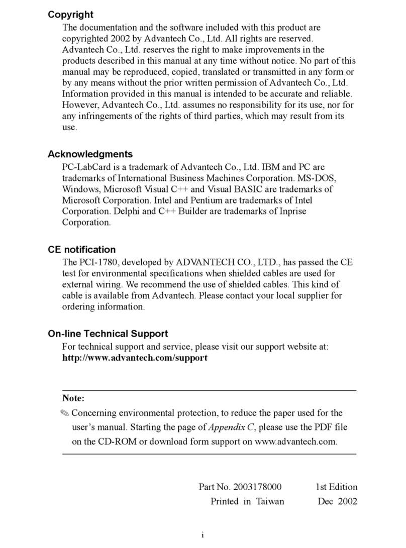
This documentation and software routines contained in the
PCLS-848-P software diskette are copyrighted 1989 by the
Advantech Co., Ltd. All rights are reserved. Advantech
Co., Ltd. reserves the right to make improvements in the
products described in this manual at any time without
notice.
No part of this manual may be reproduced, copied,
translated or transmitted, in any form or by any means
without the prior written permission of Advantech Co., Ltd.
Information provided in this manual is intended to be
accurate and reliable. However, Advantech Co., Ltd.
assumes no responsibility for its use; nor for any infringe-
ments of rights of third parties which may result from its
use.
PC-LabCard is a trademark of Advantech Co., Ltd. IBM
and PC are trademarks of International Business Machines
Corporation. MS-DOS and MS-PASCAL are trademarks of
Microsoft Corporation. TURBO PASCAL is a trademark of
Borland Inc. Intel is a trademark of Intel Corporation. Nl
PC-II is a trademark of National Instruments Corporation.
Contents
CHAPTER 1. GENERAL INFORMATION .............................................1
1.1. Introduction to the Product ......................................................................... 1
1.2. Description of the Documentation .............................................................. 2
CHAPTER 2. INSTALLATION .................................................................5
2.1. Inspection .................................................................................................... 5
2.2. Switch and Jumper Setting ......................................................................... 5
2.2.1. VO Base Address and Wait State Sethng ......................................................... 6
2.2.2. Firmware Address Setting ................................................................................. 7
2.2.3. Operating Mode Setting ..................................................................................... 8
2.2.4. DMALevel Setting ............................................................................................. 9
2.2.5. Interrupt Level (IRQ) Setting .............................................................................. 9
2.3. Installmg the Card 2.3.1. Preparation ........................................................ 9
2.3.2. Installing the Card into a PC ............................................................................ 10
2.3.3. Function Check ............................................................................................... 11
CHAVIJER 3. PROGRAM~NGREFERENCE.......................................15
3.1. Introduction ............................................................................................... 15
3.2. Using the IEEE-488 Drivers for Microsoft Pascal .................................... 16
3.3. Using the IEEE 488 Drivers for Turbo Pascal .......................................... 18
3.4. The IEEE488 Procedures and Functions ................................................. 20
3.4.1. icabort ............................................................................................................. 21
3.4.2. iedevclr ........................................................................................................... 22
3.4.3. iedevice ........................................................................................................... 23
3.4.4. ieenter ............................................................................................................. 24
3.4.5. ieentera ........................................................................................................... 25
3.4.6. iecol ................................................................................................................ 27
3.4.7. ieinit ................................................................................................................ 29
3.4.8. iello ................................................................................................................. 32
3.4.9. ielocal .............................................................................................................. 33
3.4.10. ieoutput ........................................................................................................... 34
3.4.11. ieouta .............................................................................................................. 35
3.4.12. ieppoll ............................................................................................................. 37
3.4.13. ieppollc ............................................................................................................ 38
3.4.14. ieppollu ........................................................................................................... 40
3.4.15. ieremote .......................................................................................................... 41
3.4.16. ieseg ............................................................................................................... 42
3.4.17. iesend ............................................................................................................. 43
3.4.18. iespoll .............................................................................................................. 45
3.4.19. iestatus ........................................................................................................... 46
3.4.20. ietimout ........................................................................................................... 48
3.4.21. ietrig ................................................................................................................ 49
CHAPTER 4. PROGRAMMINGEXAMPLES.......................................51
4.1. Interactive Data Transfer .......................................................................... 51
4.2. Set the IEEE 48S Printer t ........................................................................ 55
4.3. Voltage Measurement with DVM .............................................................. 57
4.4. ADSOO PMU Programming ..................................................................... 60
4.5. Multiple Device Triggering ........................................................................ 64
CHAPI.ER 5. ADVANCEDPROGRAMMINGTECHIQUES ...............67
5.1. Direct Memory Aocess (DMA) .................................................................. 67
5.2. Transfer Speed ......................................................................................... 69

5.3. Interrupt ..................................................................................................... 70
5.4. More about the Procedure iesend( ) ......................................................... 71
CHAPTER 6. DIGITAL OUTPUT...........................................................73
CHAPTER 7. THEORY OF OPERATION.............................................75
7.1. Introduction ............................................................................................... 75
7.2. Block Diagram Description ....................................................................... 75
CHAPTER 8. TROUBLE SHOOTING...................................................79
8.1. Introduction ............................................................................................... 79
8.2. Periodic Maintenance ............................................................................... 79
8.3. Troubleshooting Procedure ....................................................................... 79
8.4. Part Iist ...................................................................................................... 81
CHAPTER 9. BUS TUTORIAL ...............................................................83
9.1. General Bus Description ........................................................................... 83
9.2. Bus Structure ............................................................................................ 84
9.2.1. IEEE 488 Connector Pin Assignment .............................................................. 84
9.2.2. IEC-25 Connector Pin Assignment ................................................................. 84
9.3. Management Iines .................................................................................... 85
9.4. Bus Commands ........................................................................................ 86
9.5. Service Request and Serial Pollmg .......................................................... 87
9.6. Parallel Polling .......................................................................................... 87
9.7. Code Summary ......................................................................................... 88
9.8. Handshake lines ....................................................................................... 90
9.9. Other Bus Iines ......................................................................................... 92
9.10. Bus Operating Considerations .................................................................. 92
CHAPTER 10. ASCO TABLE..................................................................93
CHAPTER 11. NEC7210 READ/WRITE REGISTERS........................95
CHAPTER 12. SUMMARYOF PROCEDURES AND FUNCIIONS ...97
12.1. IEEE488 Procedures for hlicrosoft Pascal ............................................... 97
12.2. IEEE-488 Procedures for Turbo Pascal ................................................... 99
Figures
Figuree 7-1 PCL-848A/B Block Diagram ......................................................... 77
CHAPTER 1 GENERAL INFORMATION
1
CHAPTER 1. GENERAL INFORMATION
1.1. Introduction to the Product
The PCL-848A/B MULTIFUNCTION IEEE-488 INTERFACE CARD is a valuable
addition to your PC that allows you to communicate with over 2000 products, made
by over 200 manufacturers, in over 14 countries. The IEEE-488-1978 standard that
this IEEE-488 card implements is the most widely used international standard for
information transfer between computer and electronic instruments.
There are numerous publications and articles that may be used in conjunction with
this manual to assist you to understand the interface standard. The IEEE reference
document may be ordered by writing to the IEEE Service Center, 445 Hoes Lane,
Piscataway, NJ 08854, USA.
The IEEE-488 interface card provides the hardware (electrical and mechanical) and
software required for you to interface your PC to the IEEE-488 bus. The software is
packaged in read-only-memory (firmware) and on a diskette to provide versatile and
easy-to-use IEEE-488 procedures for your Pascal language. Firmware cannot be
accidentally erased or overwritten and it is always available for use by application
programs. This manual provides a programming reference (Chapter 3.) and program-
ming techniques (Chapter 4. and 5.) to assist you in writing your own application
programs.
The key features of this interface card include:
*Operating in one of the two modes (switch selectable).
Mode A: Compatible with the PCL-748 IEEE-488 interface card and use the same
IEEE-488 function set.
Mode N:Software compatible with National Instrument PC-II and IBM-PC GPIB
adaptor and use the driver and software developed for them.
*Implementation of the entire IEEE-488 standard.
*Powerful and easy-to-use software command set. Fewer argu ments and simple
initialization.
*On-board RAMfor working space. No system memory space is needed for the
IEEE-488 interface operation.
2PCLS-848-P User's Manual
*Built-in 16 bit digital output port provides a convenient and economical solution for
signal switching and digital control applications. The D/O port is compatible with
the daughter boards: PCLD-785 Relay Output Board, PCLD-786 SSR & Relay
Driver Board and PCL-789 Amplifier & Multiplexer Board.
*The software can change the PC printer port to an IEEE-488 device. The PrtSc
(print screen) key, all print statements, word processing and spreadsheet programs
that use printer driver in BIOS can use IEEE-488 printers.
*High speed direct memory access (DMA) with the ability to handle 64K byte
arrays.
*Programmable system controller, active controller or device functions.
*All device functions, addresses, interrupt conditions, and parallel poll responses are
programmable.
*DIP switch selectable wait states (0/2/4/6 wait states) to ensure the compatibility to
very high speed PC’s.
*PCL-848A offers the connectors of the IEEE-488 standard while PCL-848B uses
the 25 pin D type connectors for the IEC-625 standard.
*Each device on the IEEE-488 bus can be assigned with its own terminator.
1.2. Description of the Documentation
Information in this manual is given at several levels of detail and is organized to allow
you work through the TUTORIAL, PROGRAMM ING REFERENCE and PRO-
GRAMMINGEXAMPLES chapters.
If you have no IEEE-488 experience, go to Chapter 9 after this chapter. The IEEE-488
TUTORLAL in Chapter 9 is designed to give you a thorough understanding of how
the IEEE-488 General Purpose Interface Bus (GP-IB) works. Topics in the TUTORI-
AL should be read in sequence if you have no IEEE-488 background and intend to
write application programs. With a solid understanding of the basic IEEE-488
concepts, followed by returning to the PROGRAMMING REFERENCE, and the
PROGRAMMINGEXAMPLES, you should be able to program almost any IEEE-
488 bus system without interface problems.
CHAPTER 1 GENERAL INFORMATION
3
If you are familiar with the basic concepts of the IEEE-488 bus you may want to
begin reading Chapter 3 PROGRAMMINGREFERENCE. This chapter describes the
statement syntax and techniques to use the IEEE-488 driver. Chapter 4 PROGRAM-
MINGEXAMPLES will show you how the procedures are used in typical applica-
tions and also provide you with useful program examples for your own applications.
If you want to know more details about this IEEE-488 interface card, please refer to
Chapter 5 ADVANCED PROGRAMMING TECHNIQUES. This chapter tells you
how to set DMA, how to modify transfer speed and how to use interrupts.
This manual is intended to be accurate and is organized to give you a quick reference
for programming ideas and the concepts of the IEEE-488 bus.
4PCLS-848-P User's Manual
CHAPTER 2 INSTALLATION
5
CHAPTER 2. INSTALLATION
2.1. Inspection
When unpacking, check the unit for signs of shipping damage (damaged box, scratches,
dents, etc). If there is any damage to the unit or it fails to meet specifications, notify
your local sales representative immediately.
2.2. Switch and Jumper Setting
This IEEE-488 interface card has two DIP switch (SW1 and SW2), one slide switch
(SW3) and three jumpers (JP1, JP2 and JP3). The setting must be coincident with the
application program.
Figure2.2.Locationofswitches and jumpers
6PCLS-848-P User's Manual
2.2.1. VO Base Address and Wait State Sethng
The I/O ports base address and the number of wait states are selectable by the 8
position DIP switch SW1. The base address can be set anywhere in the I/O address
area from hex 200 to hex 3F0 and the wait states can be set to 0, 2, 4, or 6. Refer to
Figure 2.2. for the locations of the DIP switches SW1. Factory settings of these
switches are hex 2B0 and zero wait state.
This multifunction interface card takes 16 addresses of I/O port following the base
address. The digital output port takes the addresses of BASE+0and BASE+1 and the
IEEE-488 interface takes the addresses from BASE+8 to BASE+15. When using the
IEEE-488 gt driver routines, the IEEE-488 interface base address must be set to
BASE+8 where BASE is the setting of DIP switch SW1. The default address of the
IEEE-488 interface is hex 2B8.
The switch settings for various base addresses and wait states are illustrated as below:
Note: - 0N = 0, 0FF = 1
- 1..8 are switch position
- W0..W1 correspond to wait state
- A4..A8 correspond to address lines of the PC bus
- * means factory setting
Switch position (SW1)
1 2 3 4 5 Occupied
A8 A7 A6 A5 A4 Addresses
00000200-20F
0 0 0 0 1 210-21F
•
•
•
010112B0-2BF
•
•
111103E0-3EF
111113F0-3FF
*
CHAPTER 2 INSTALLATION
7
Switch position (SW1)
7 8 Wait state(s)
W1 W0
O O O
O 1 2
1 0 4
1 1 6
2.2.2. Firmware Address Setting
The IEEE-488 interface driver routine is stored in the on-board EPROM. The memory
address of this firmware can be selected by SW2. The memory segment of the
firmware can be from hex 8000 to hex FC00. Factory setting is hex D000.
The range of these locations is out of the 640K system memory of the IBM PC, PC/
XT and PC/AT. However, choice of this location must be made to avoid any conflict
with other interface cards. When two or more IEEE-488 interface cards are used in one
PC, the location settings must be different in order to have different working space
although the firmware code is the same.
The SW2 positions 1 to 5 determine the address bits A18 to A14. Address bit A19 is
always 1. Address bits below A13 (included) are not cared.
*
8PCLS-848-P User's Manual
Memory Location Segment SW2-1 SW2-2 SW2-3 SW2-4 SW2-5
(hex) Al8 A17 A16 A15 A14
8000 0 0 0 0 0
8400 0 0 0 0 1
8800 0 0 0 1 0
•
•
Reserved A000 0 1 0 0 0
•
•
CRT display B000 0 1 1 0 0
•
•
Factory setting D000 1 0 1 0 0
•
•
System ROM F000 1 1 1 0 0
FC00 1 1 1 1 1
* 0 : ON 1 : OFF
This multifunction IEEE-488 interface card takes 10K bytes of the memory space
including 8K byte ROM and 2K byte RAM. The starting address of the working
RAM is offset 8K bytes from the ROM starting address.
2.2.3. Operating Mode Setting
SW3 is a slide switch to select the operating mode. When it is set to “A”, this card is
compatible with the easy-to-use PCL-748 IEEE-488 interface card except there is no
real time clock. When SW3 is set to “N”, this card becomes Nl PC-II compatible.
It depends on the users which mode is selected. If the software package is already
developed for PC-II, then mode “N” can be used to eliminate the software effort.
However, for new software developing, mode “A” is recommended to get all the
benefit of PCL-848A/B. The PCL-848A/B does not offer the software driver to use
mode “N” and this manual offers the information for mode “A” operation only.
CHAPTER 2 INSTALLATION
9
2.2.4. DMALevel Setting
The PCL-848A/B is designed to permit DMA(Direct Memory Access) data transfer
between IEEE-488 bus and the system RAM of the PC. The DMAlevel is set by JP1
and JP2. The JP1 is for DACK signal 3! path while the JP2 is for DRQ. The settrugs
of JP1 and JP2 must be coincident. For example, if the JP1 is set to DACK3, then JP2
must be set to DRQ 3.
2.2.5. Interrupt Level (IRQ) Setting
The PCL-848A/B is designed to permit access to interrupt level 2 up to level 7 and
the interrupt is initiated by the NEC7210 GP interface controller. The selection is
made by setting JP3.
Note: Although the IRQ level can be set from IRQ 2 to IRQ 7 on the
board, the firmware supports IRQ 2, 3, 5, and 7 only.
2.3. Installmg the Card 2.3.1. Preparation
Discharge any static electricity by touching the back of the system s~ unit before you
handle the board. You should avoid contact with e)3 materials that create static
electricity such as plastic, vinyl, and styrofoam.
The IEEE-488 interface card is setup at the factory of default setting:
10 PCLS-848-P User's Manual
Jumper/Switch Selection Default setting
SW1 1-5 I/O port base address Hex 2B0
SW1 7-8 Wait states 0
SW2 Firmware base address Hex D000
SW3 Operating mode A
JP1 DACK level 1
JP2 DRQ level 1
JP3 IRQ level 7
Refer to Section 2.2. for other configurations.
2.3.2. Installing the Card into a PC
The procedure to install the IEEE-488 interface card is as following:
1. Turn off the computer and any peripheral devices (such as printers and monitors).
2. Disconnect the power cord and any other cables from the back of the computer.
Turn the system unit so the back of the unit faces you.
3. Remove the system unit cover (See your computer user’s guide if necessary).
4. Locate the expansion slots at the rear of the unit and choose any unused slot.
5. Remove the screw that secures the expansion slot cover to the system unit. (Save
the screw to secure the IEEE-488 interface card retaining bracket).
6. Carefully grasp the upper edge of the IEEE-488 interface card. Align the hole in the
retaining bracket with the hole on top of the expansion slot, and align the gold
striped edge connector with the expansion slot socket. Press the board firmly into
the socket.
7. Replace the screw in the expansion slot retaining bracket.
8. Replace the system unit cover. Connect the cables you removed in step 2.
CHAPTER 2 INSTALLATION
11
2.3.3. Function Check
Confirm proper operation by connecting an IEEE-488 instrument to the bus and
attempting to operate it with a demo program written in Pascal.
Here is an example that uses an HP3478A digital voltmeter and a short Pascal
program. If an HP3478A is not available and you have p~another IEEE-488 instru-
ment, you need to modify the instrument programming code in the program source.
The program files MSP DEMO.EXE and TBP_DEMO.PAS are in the diskette
attached with this package. The source code of these demo programs are listed after
the test steps.
1. Connect the HP3478A DVM to the IEEE-488 bus connector of this card on the
back of the PC with a standard IEEE-488 cable. On the PCL-848B, the connector is
25 pin D type defined by IEC-625 and a PCL-15488-2 IEC-625 to IEEE-488 cable
must be used.
2. Set the device address of the HP3478A DVM to 23.
3. Turn on the HP3478A DVM and the PC.
4. Put the Demo/Library diskette into drive a:.
5. For Microsoft Pascal: Execute the program MSP DEMO.EXE by typing in
A:MSP_DEMO <return> For Turbo Pascal: Enter the Turbo Pascal and load the
source file TBP_DEMO.PAS. Press ‘R’ to run this program.
6. The CRT will display the 10 readings measured by the HP3478A DVM and thus
confirm proper operation.
If the system fails this test, check for these common problems:
12 PCLS-848-P User's Manual
1. The instrument requires a special terminator. Check the instruments instruction
manual and Chapter 4 of this manual.
2. The programming command syntax for the instrument may be incorrect. Check the
examples in the instrument manual.
3. Check all electrical connections.
4. The memory segment hex D000 is occupied by other add-on cards. Remove these
cards if you can. Otherwise, change the DIP switch SW2 and the program for a new
address such as 17;\ hex E000.
5. The I/O port addresses hex 2B0 to 2BF are occupied by other add-on cards.
Remove these cards if you can. Otherwise, change the DIP switch SW1 and the
program for a new address such as hex 2A0.
Contact your local sales representative for further assistance.
Demo Program for Microsoft Pascal
program demol(input,output);
procedureieseg(progseg:word);extern;
procedure ieinit(ioport,myaddr,setting:integer);extern;
procedure ieoutput(addr:integer;var outstr:lstring);extern;
procedure ieenter(addr:integer;var instr:lstring);extern;
varoutstr,instr: lstring(l00);
addr,i,ioport,myaddr,setting: integer;
begin
addr := 23;
ieseg(16#D000);
ioport :=16Y2B8; myaddr :=21; setting :=0;
ieinit(ioport,myaddr,setting);
outstr := ‘FlTlNSRA’;
ieoutput(addr,outstr);
for i := 1 to 10 do
begin ieenter(addr,instr);
writeln(i,’ ‘,instr);
end;
end.
CHAPTER 2 INSTALLATION
13
Demo Program for Turbo Pascal
program demol(input,output);
{$I TBPGPIB.INC}
varoutstr,instr: str;
addr,i,ioport,myaddr,setting: integer;
begin
addr := 23;
ioport :=$2B8; myaddr :=21; setting :=0;
ieinit(ioport,myaddr,setting);
outstr := ‘FlTlNSRA’;
ieoutput (addr,outstr);
for i := 1 to 10 do
begin instr:=’
ieenter(addr,instr);
writeln(i,’ ‘,instr);
end;
end.
14 PCLS-848-P User's Manual

Other Advantech PCI Card manuals

Advantech PCI-COMM Series User manual

Advantech

Advantech PCI-COMM Series User manual

Advantech PCIE-1763AH User manual

Advantech

Advantech PCIE-1763AH User manual

Advantech PCI-1753 User manual

Advantech

Advantech PCI-1753 User manual

Advantech UNO-P166 Installation and operation manual

Advantech

Advantech UNO-P166 Installation and operation manual

Advantech PCI-1706U User manual

Advantech

Advantech PCI-1706U User manual

Advantech PCIE-1754 User manual

Advantech

Advantech PCIE-1754 User manual

Advantech PCIE-1753 User manual

Advantech

Advantech PCIE-1753 User manual

Advantech PCI-1625U User manual

Advantech

Advantech PCI-1625U User manual

Advantech MIC-3756 User manual

Advantech

Advantech MIC-3756 User manual

Advantech PCM-3641I Installation and operation manual

Advantech

Advantech PCM-3641I Installation and operation manual

Advantech PCI-1712 Installation and operation manual

Advantech

Advantech PCI-1712 Installation and operation manual

Advantech PCI-1680U User manual

Advantech

Advantech PCI-1680U User manual

Advantech PCI-1202 User manual

Advantech

Advantech PCI-1202 User manual

Advantech DVP-7635HE User manual

Advantech

Advantech DVP-7635HE User manual

Advantech PCIE-1802 User manual

Advantech

Advantech PCIE-1802 User manual

Advantech DSPC-8682 User manual

Advantech

Advantech DSPC-8682 User manual

Advantech PCI-1710U-DE User manual

Advantech

Advantech PCI-1710U-DE User manual

Advantech PCI-1755 User manual

Advantech

Advantech PCI-1755 User manual

Advantech PCI-1733 Installation and operation manual

Advantech

Advantech PCI-1733 Installation and operation manual

Advantech PCIE-1803 Installation and operation manual

Advantech

Advantech PCIE-1803 Installation and operation manual

Advantech PCI-1751U User manual

Advantech

Advantech PCI-1751U User manual

Advantech PCIE-1884 Installation and operation manual

Advantech

Advantech PCIE-1884 Installation and operation manual

Advantech MIC-3756 User manual

Advantech

Advantech MIC-3756 User manual

Advantech PCM-2312 User manual

Advantech

Advantech PCM-2312 User manual

Popular PCI Card manuals by other brands

Gembird CHM-02 user manual

Gembird

Gembird CHM-02 user manual

Amfeltec Corp. Flexible MiniPCI Express to PCI Bus Adapter Hardware manual

Amfeltec Corp.

Amfeltec Corp. Flexible MiniPCI Express to PCI Bus Adapter Hardware manual

HP 435508-B21 Quickspecs

HP

HP 435508-B21 Quickspecs

Hauppauge WinTV-HVR-1265 Quick installation guide

Hauppauge

Hauppauge WinTV-HVR-1265 Quick installation guide

ORiNG PCard-E 041L-D4 Series Quick installation guide

ORiNG

ORiNG PCard-E 041L-D4 Series Quick installation guide

Matrox Vio Installation and Hardware Reference

Matrox

Matrox Vio Installation and Hardware Reference

AudioCodes SmartWORKS NGX Quick install

AudioCodes

AudioCodes SmartWORKS NGX Quick install

Xilinx Alveo U50 user guide

Xilinx

Xilinx Alveo U50 user guide

Digicom 10/100 user guide

Digicom

Digicom 10/100 user guide

Gemtek WMIA-165G user guide

Gemtek

Gemtek WMIA-165G user guide

Rosewill RC-301E user manual

Rosewill

Rosewill RC-301E user manual

Supermicro AOC-STGN-i2S user manual

Supermicro

Supermicro AOC-STGN-i2S user manual

NuDAQ PCI-7230 user guide

NuDAQ

NuDAQ PCI-7230 user guide

YASKAWA VS-616G5 Series instructions

YASKAWA

YASKAWA VS-616G5 Series instructions

NETGEAR WG311v2 - 54 Mbps Wireless PCI Adapter installation guide

NETGEAR

NETGEAR WG311v2 - 54 Mbps Wireless PCI Adapter installation guide

Buffalo WLI2-PCI-G54S Quick setup guide

Buffalo

Buffalo WLI2-PCI-G54S Quick setup guide

ANTAIRA MSC-202ALP installation guide

ANTAIRA

ANTAIRA MSC-202ALP installation guide

Wiligear WMR-400 Operation manual

Wiligear

Wiligear WMR-400 Operation manual

manuals.online logo
manuals.online logoBrands
  • About & Mission
  • Contact us
  • Privacy Policy
  • Terms and Conditions

Copyright 2025 Manuals.Online. All Rights Reserved.