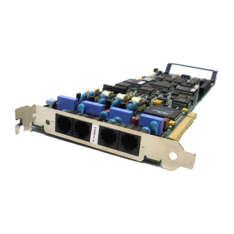
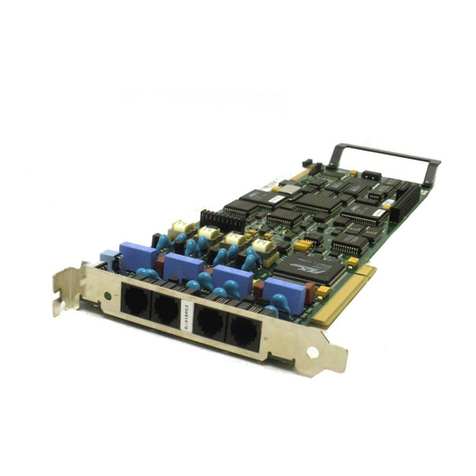
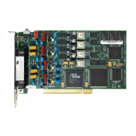
Dialogic D/41JCT-LS Use and care manual

Dialogic PCI and Euro PCI Linecards
Installation and Replacement
S p a r e P a r t s D o c u m e n t

ii D i a l o g i c P C I L i n e c a r d s
1081-50821-00 Rev 01 October 2011
Edition Note
This is the first edition of the Dialogic®PCI and Euro PCI Linecards Installation and
Replacement Spare Parts Document. Information in this document applies to OneBox systems
with version 5.0 and later.
P/N 1081-50821-00 Rev 01 © October 2011
Copyright Notice
© 2011 Aastra®Technologies Limited. All rights reserved.
This document contains proprietary information, which is protected by copyright.
No part of this document may be reproduced or transmitted in any form or by any means,
electronic or mechanical, including photocopying, recording, or by any information storage
and retrieval system, or translated into another language, without the prior written consent of
Aastra Technologies Limited, Concord, Ontario, Canada.
NOTICE
The information in this document is subject to change without notice.
Aastra MAKES NO WARRANTY OF ANY KIND WITH REGARD TO THIS MATERIAL,
INCLUDING, BUT NOT LIMITED TO, THE IMPLIED WARRANTIES OF
MERCHANTABILITY AND FITNESS FOR A PARTICULAR PURPOSE. Aastra shall not be
liable for errors contained herein, neither for incidental nor for consequential damages in
connection with the furnishing, performance, or use of these materials.
Aastra Technologies Limited
Concord, Ontario, Canada.
Trademarks
Aastra OneBox and Aastra are registered trademarks Aastra Technologies Limited.
Dialogic is a registered trademark of Dialogic Corporation.
Windows is a registered trademark of Microsoft Corporation.
All other products, brand names, or companies mentioned in this document may be
trademarks or registered trademarks of their respective companies.

D i a l o g i c P C I L i n e c a r d s i i i
1081-50821-00 Rev 01 October 2011
Table of Contents
Preface...................................................................................................................................... v
References.............................................................................................................................v
Help........................................................................................................................................v
Online Books.........................................................................................................................vi
Document Conventions.........................................................................................................vi
Frequently Used Terms .........................................................................................................vi
Overview................................................................................................................................... 1
Electrostatic Discharge (ESD) Warning ................................................................................. 1
Gathering Tools and Equipment............................................................................................. 1
Dialogic D/41JCT-LS and D/41JCT-LS Euro PCI Linecard Technical Specifications........... 2
Cabling D/41JCT-LS Linecards to the Telephone System...................................................... 3
Dialogic D/42JCT-U and D/82JCT-U PCI Linecard Technical Specifications........................ 5
D/42JCT-U Linecard.............................................................................................................. 5
D/82JCT-U Linecard.............................................................................................................. 6
Understanding D/42 and D/82 Linecard Identification............................................................ 7
Cabling D/42JCT-U and D/82JCT-U PCI Linecards to the Telephone System....................... 7
Dialogic D/120JCT-LS and D/120JCT-LS Euro PCI Linecard Technical Specifications....... 9
Cabling D/120JCT-LS PCI Linecards to the Telephone System............................................10
Dialogic D/240JCT-T1 PCI Linecard Technical Specifications.............................................12
Cabling D/240JCT-T1 PCI Linecards to the Telephone System............................................13
Dialogic D/480JCT-T1 PCI Linecard Technical Specifications.............................................15
Cabling D/480JCT-T1 PCI Linecards to the Telephone System............................................17
Preparing Dialogic PCI Linecards for Installation.................................................................18
Assigning the Linecard Identification Number.......................................................................18
Configuring the Default Line State (D/41 and D/120 only) ....................................................19
Removing the Slot Retainer Bracket.....................................................................................19
Installing Dialogic PCI Linecards in the Platform.................................................................20
Installing the H.100 Bus Cable .............................................................................................21

iv D i a l o g i c P C I L i n e c a r d s
1081-50821-00 Rev 01 October 2011
Installing Dialogic Software ...................................................................................................22
Configuring Dialogic PCI Linecards in Dialogic Configuration Manager - DCM.................23
Appendix A—Manually Adding a Linecard to the Configured Devices List........................25
Addendum B—Configuring the D/42JCT or D/82JCT for Your Station Set Emulation .......26

D i a l o g i c P C I L i n e c a r d s v
1081-50821-00 Rev 01 October 2011
Preface
This document is written for Aastra certified OneBox technicians who are experienced with
OneBox and are familiar with its procedures and terminology. This book assumes you are
familiar with OneBox and the Microsoft Windows®operating system.
This installation guide consists of the following parts:
An Overview of the Dialogic PCI linecards
Dialogic D/41 JCT PCI linecard specifications and configurations
Dialogic D/42 and D/82 JCT PCI linecard specifications and configurations
Dialogic D/120 JCT PCI linecard specifications and configurations
Dialogic D/240 JCT PCI linecard specifications and configurations
Dialogic D/480 JCT PCI linecard specifications and configurations
Installing the linecard in the Call Server platform
Configuring the linecard for service in the Call Server platform
References
Information that is more current may be available from the following sources:
World Wide Web—http://www.dialogic.com
NOTE For a list that provides information for registering Dialogic linecards in many
countries, contact Dialogic or retrieve a copy of their Global Product Approvals list from
their website.
The following Aastra documents are available for your reference:
Installing OneBox
Administering OneBox
Removing and Installing Dialogic and Aculab Software Support Components system
installation manual
Help
The primary source of information about OneBox is the online help available within any of its
administrative utilities. You can consult Help by taking one of the following steps:
Click the Help button in the dialog box or window in which you are working
Press the F1 key at any time.
Selecting the Index and Contents tabs from the Help menu causes Help to display an index
system and table of contents that cross-references all OneBox Help files, enabling installers,
and system administrators to pinpoint the information they need with as little time and effort as
possible.

vi D i a l o g i c P C I L i n e c a r d s
1081-50821-00 Rev 01 October 2011
Online Books
Included on the OneBox Telephony Server DVD is a catalog of technical documentation. Refer
to the appropriate technical documentation for additional application and installation information.
Aastra produces technical documentation in Adobe Acrobat PDF format and requires the Adobe;
Acrobat Reader program to view it. You can download the program from http://www.adobe.com.
Document Conventions
The following conventions apply to information in this guide:
Bold font
Indicates text you type; enter the information exactly as shown. It also
indicates buttons and commands that you click or select from menus.
Italics
Italics are used to introduce or emphasize a term. In addition, titles of other
documents are shown in italics.
Mono-space
Indicates XML blocks, XML element and attribute names, Parameter names,
structure names, code elements within text, errors, error numbers, and error
strings, PBX commands and programming examples
WARNING A warning paragraph advises you of circumstances that can result in the loss of
data, harm to the telephony server platform, or personal harm.
IMPORTANT An important paragraph gives decision-making information or informs you of the
order in which tasks need to be completed.
NOTE Anote gives additional information, provides an explanation, or indicates an exception to
the information in the preceding text.
Frequently Used Terms
The terms System Server and Call Server refer to an organization’s computer platforms that
have OneBox software installed and are dedicated for use as the organizations unified
messaging servers.
The term Telephony Server refers generically to the System Server platform, the Call Server
platform, or both. The term is most often used to describe a software or hardware installation or
configuration practice where the role of the server platform is not specifically expressed.

D i a l o g i c P C I L i n e c a r d s 1
1081-50821-00 Rev 01 October 2011
Overview
This document describes how to install or replace one or more Dialogic®PCI or Euro PCI
linecards in a Call Server platform. The information in this document pertains to platforms
running OneBox version 5.0 and later.
Specific information pertaining to each type of linecard is contained within a separate section of
this document for each linecard type. General information about the Dialogic PCI linecard such
as installing the card in the system and installing Dialogic software is located in the section
specific to the required task.
Aastra recommends that you read the section specific to the linecard you are installing, and
then read remainder of the document before disassembling the hardware.
IMPORTANT Hardware conflicts and configuration issues can occur between hardware devices
installed in a computer platform. Because Aastra sells Dialogic PCI linecards as a kit for
installation in computer platforms that we have not tested, the compatibility of these cards in
your computer platform cannot guaranteed. Aastra can offer troubleshooting advice and
assistance to the best of its knowledge and ability. However, you are ultimately responsible for
resolving all hardware conflicts and configuration issues in the platform.
NOTE Dialogic ISA linecards are not supported in OneBox versions 5.0 and later. If ISA
linecards are installed in the platform, they must be removed.
Electrostatic Discharge (ESD) Warning
Computer components are extremely sensitive to electrostatic discharge (ESD). You must wear
an anti-static wrist strap and install the linecard at an ESD-safe workstation. Do not open the
static-protective container until necessary. Before removing the linecard from the static-
protective container, touch the container to a grounded, unpainted metal surface for at least two
seconds (this drains the static electricity from the container and from your body). Turn off and
unplug your computer before removing the case.
Gathering Tools and Equipment
Before you begin disassembling the Call Server platform, verify that you have the following
required tools and equipment:
OneBox Telephony Server DVD
One or more Dialogic PCI or Euro PCI linecards specific to the telephony resources you
are installing
H.100 bus cable to connect multiple PCI cards
New Feature file or License key to add additional lines
Linecord adapters, if necessary
2 D i a l o g i c P C I L i n e c a r d s
1081-50821-00 Rev 01 October 2011
Dialogic D/41JCT-LS and D/41JCT-LS Euro PCI
Linecard Technical Specifications
Table 1 lists the technical specifications for the Dialogic D/41JCT-LS and D/41JCT-LS Euro
linecards approved for use with OneBox. Figure 1 shows the general layout of these linecards.
NOTE Your local telephone company may require some of these specifications. For example, in
the United States, some telephone companies require an FCC registration number if the
linecard is connected directly to central office (CO) lines. Contact your local telephone company
for its requirements.
Table 1: D/41JCT-LS and D/41JCT-LS Euro Technical Specifications
Feature
Specification
Number of Ports
1—4; the OneBox port assignment is determined by the linecard
identification number
Dialing
DTMF
FCC registration number
US: EBZUSA-75385-VM-T
Analog network interface
On-board loop start interface circuits
Voice coding
PCM
Host interface bus
Standard PCI, 3.3-volt or 5-volt slots
Figure 1: Layout of the D/41-JCT-LS PCI linecard
SW30
H.100 Bus Connector
SW4
PCI Connector
Slot Retainer Bracket

D i a l o g i c P C I L i n e c a r d s 3
1081-50821-00 Rev 01 October 2011
Cabling D/41JCT-LS Linecards to the Telephone System
Once the D/41JCT-LS linecard are installed in the platform, you can cable the platform to the
telephone system. OneBox assigns port numbers in ascending order based on the linecard
identification number. For example, a D/41JCT-LS linecard to which you assigned the linecard
ID 1 is assigned line numbers 1–4; a D/41JCT-LS linecard to which you assigned the linecard ID
2 is assigned line numbers 5-8 (Figure 2). Refer to the topic, ―Assigning the Linecard
Identification Number‖ for information on assigning the linecard ID. Keep this assignment
scheme in mind when connecting each D/41JCT-LS linecard to the telephone system.
Figure 2: Line assignment scheme for the D/41JCT-LS linecard
There are four RJ-11 connectors on the rear bracket of the D/120JCT-LS linecards. Figure 3
shows the pin-out of these modified connectors.
Pin 4: Tip 1
Pin 3: Ring 1
Figure 3: Pin-outs of the modified RJ-11 connector
D/41JCT-LS linecards require RJ-11 connectors to interface with the telephone system. You
may need linecord adapters to connect to the Cal Server platform depending on the type of line
interface installed at your site. If linecord adapters are required and not included with the
linecards, please contact your Customer Service representative.
Linecard
ID#1
Linecar
d
ID# 2
Line 1
Line 5
Line 2
Line 6
Line 3
Line 7
Line 4
Line 8

4 D i a l o g i c P C I L i n e c a r d s
1081-50821-00 Rev 01 October 2011
To cable D/41JCT-LS linecards…
Plug the linecords from the telephone system into the RJ-11 connectors on the D/41JCT-LS.
Or,
If the provided telephone line interface is not an RJ-11 connector, plug the linecords into the
appropriate linecord adapter, and then plug the RJ-11 linecord(s) of the adapter into the RJ-11
connector of the D/41JCT-LS.

D i a l o g i c P C I L i n e c a r d s 5
1081-50821-00 Rev 01 October 2011
Dialogic D/42JCT-U and D/82JCT-U PCI
Linecard Technical Specifications
D/42JCT-U Linecard
The D/42JCT-U linecard is essentially a lower-cost, half-capacity version of the D/82JCT-UNIV
linecard.
Table 2 lists the technical specifications for the Dialogic D/42JCT-U PCI linecard approved for
OneBox. Figure 4 shows the general layout of these linecards.
Table 2: D/42JCT-U linecard Technical Specifications
Feature
Specification
Number of ports
Total ports/system
Maximum boards/system
4 ports per linecard
16 (if only D/42JCT-U are installed)
4 linecards
Telecommunications
registrations
US: EBZUSA-34995-CE-T
Canada: IC: 885 10638A
Analog network interface
On-board loop start interface circuits
Voice coding
PCM (supports OKIADPCM, G.711 µ-law, G.711 A-law, PCM
and GSM codecs)
Host interface bus
Standard PCI, 3.3-volt or 5-volt slots
Figure 4: Layout of the D/42JCT-U PCI linecard
H.100 Bus Connector
Board ID Display
36-pin Connector
Retainer Slot Bracket
PCI Connector
Rear Bracket

6 D i a l o g i c P C I L i n e c a r d s
1081-50821-00 Rev 01 October 2011
D/82JCT-U Linecard
Dialogic provides versions of the D/82 linecard to support both 3.3-volt and 5-volt PCI buses.
The 5-volt version is referred to as the D/82JCT-U. Because the 3.3-volt version is also
compatible with 5-volt buses, Dialogic refers to it as the D/82JCT-U-PCI-UNIV linecard. In this
document the abbreviated term, D/82JCT-UNIV refers to the same linecard.
Table 3 lists the technical specifications for the Dialogic D/82JCT-U PCI linecard approved for
OneBox. Figure 5 shows the general layout of these linecards.
Table 3: D/82JCT-U linecard Technical Specifications
Feature
Specification
Number of ports
Total ports/system
Maximum boards/system
8 ports per linecard
64
8 linecards
Telecommunications
registrations
US: EBZUSA-34995-CE-T
Canada: IC: 885 10638A
Analog network interface
On-board loop start interface circuits
Voice coding
PCM (supports OKIADPCM, G.711 µ-law, G.711 A-law, PCM
and GSM codecs)
Host interface bus
Standard PCI, 5-volt slots only (D/82JCT-U)
Standard PCI, 3.3-volt or 5-volt slots (D/82JCT-UNIV)
Figure 5: Layout of the D/82CT-U PCI linecard
PCI Connector
H.100 Bus Connector
Slot Retainer Bracket
Board ID Display
36-pin Connector
Rear Bracket

D i a l o g i c P C I L i n e c a r d s 7
1081-50821-00 Rev 01 October 2011
Understanding D/42 and D/82 Linecard Identification
Before installing a Dialogic D/42JCT-U or D/82JCT-U PCI linecard in the Call Server platform,
familiarize yourself with the board identification numbering scheme of these cards. Each D/42 or
D/82 linecard is assigned a Board ID number automatically as the Call Server platform starts.
After the start-up sequence has finished, the Board ID appears on a two-character LED display
located on the card’s rear bracket.
NOTE The interval between system start-up and the Board ID appearing on the LED display
varies with system configurations. You may have to wait up to several minutes for the Board ID
to appear.
Cabling D/42JCT-U and D/82JCT-U PCI Linecards to the
Telephone System
Each D/42 or D/82 linecard connects to the telephone system through a Dialogic D/82-U PBX
interface cable assembly as shown in Figure 6. A cable assembly ships with each D/42 or D/82
linecard.
NOTE The cable assembly is less than 18 inches (45.7 cm). A 25-pair cable with RJ-21
Amphenol ends may be required to connect to the telephone system’s distribution frame.
Figure 6: Cabling a D/42 or D/82 linecard to the telephone system
To cable Dialogic D/42JCT-U, D/82JCT-U, or D/82JCT-UNIV linecards to the telephone
system…
Attach the 25-pair male RJ-21 plug to the wired RJ-21 connector of the telephone
system.
Attach the mini-D 36-pin plug to the mini-D 36-pin connector on the rear bracket of the
linecard.
NOTE Country-specific linecord adapters may be required to connect the Call Server platform to
the telephone system. If these adapters are required and not included with the linecards, please
contact a telecom equipment supplier in your area.
Table 4 details the wiring connections for both 4-wire and 2-wire digital stations. The 4-wire
stations use both the odd and even wire pairs, while the 2-wire stations connect to the even
numbered pairs only. Note that because the D/42JCT-U linecard has half the capacity of the
D/82 linecards, it uses only the first four 4-wire or 2-wire pairs in the D/82-U cable assembly.

8 D i a l o g i c P C I L i n e c a r d s
1081-50821-00 Rev 01 October 2011
Table 4: Dialogic D/42 and D/82 wire connections
Pair
Color
4-wire
2-wire
Usage
1
White/Blue
T (Port 1)
D/42 and D/82 linecards
Blue/White
R (Port 1)
D/42 and D/82 linecards
2
White/Orange
T1 (Port 1)
T (Port 1)
D/42 and D/82 linecards
Orange/White
R1 (Port 1)
R (Port 1)
D/42 and D/82 linecards
3
White/Green
T (Port 2)
D/42 and D/82 linecards
Green/White
R (Port 2)
D/42 and D/82 linecards
4
White/Brown
T1 (Port 2)
T (Port 2)
D/42 and D/82 linecards
Brown/White
R1 (Port 2)
R (Port 2)
D/42 and D/82 linecards
5
White/Slate
T (Port 3)
D/42 and D/82 linecards
Slate/White
R (Port 3)
D/42 and D/82 linecards
6
Red/Blue
T1 (Port 3)
T (Port 3)
D/42 and D/82 linecards
Blue/Red
R1 (Port 3)
R (Port 3)
D/42 and D/82 linecards
7
Red/Orange
T (Port 4)
D/42 and D/82 linecards
Orange/Red
R (Port 4
D/42 and D/82 linecards
8
Red/Green
T1 (Port 4)
T (Port 4)
D/42 and D/82 linecards
Green/Red
R1 (Port 4)
R (Port 4)
D/42 and D/82 linecards
9
Red/Brown
T (Port 5)
D/82 linecards only
Brown/Red
R (Port 5)
D/82 linecards only
10
Red/Slate
T1 (Port 5)
T (Port 5)
D/82 linecards only
Slate/Red
R1 (Port 5)
R (Port 5)
D/82 linecards only
11
Black/Blue
T (Port 6)
D/82 linecards only
Blue/Black
R (Port 6)
D/82 linecards only
12
Black/Orange
T1 (Port 6)
T (Port 6)
D/82 linecards only
Orange/Black
R1 (Port 6)
R (Port 6)
D/82 linecards only
13
Black/Green
T (Port 7)
D/82 linecards only
Green/Black
R (Port 7)
D/82 linecards only
14
Black/Brown
T1 (Port 7)
T (Port 7)
D/82 linecards only
Brown/Black
R1 (Port 7)
R (Port 7)
D/82 linecards only
15
Black/Slate
T (Port 8)
D/82 linecards only
Slate/Black
R (Port 8)
D/82 linecards only
16
Yellow/Blue
T1 (Port 8)
T (Port 8)
D/82 linecards only
Blue/Yellow
R1 (Port 8)
R (Port 8)
D/82 linecards only

D i a l o g i c P C I L i n e c a r d s 9
1081-50821-00 Rev 01 October 2011
Dialogic D/120JCT-LS and D/120JCT-LS Euro
PCI Linecard Technical Specifications
Table 5 lists the technical specifications for the Dialogic D/120JCT-LS and D/120JCT-LS Euro
PCI linecards approved for use with OneBox. Figure 7 shows the general layout of these
linecards.
NOTE Your local telephone company may require some of these specifications. For example, in
the United States, some telephone companies require an FCC registration number if the
linecard is connected directly to central office (CO) lines. Contact your local telephone company
for its requirements.
Table 5: D/120JCT-LS Technical Specifications
Feature
Specification
Number of Ports
1—12; the Call Server port assignment is determined by the linecard
identification number
Dialing
DTMF
FCC registration
number
US: EBZUSA-34827-KX-N
Analog network
interface
On-board loop start interface circuits
Voice coding
PCM
Host interface bus
Standard PCI, 5-volt slots only (D/120JCT-LS)
Standard PCI, 3.3-volt or 5-volt slots (D/120JCT-LS Euro)
Standard PCI, 3.3-volt or 5-volt slots (D/120 JCT-LS Rev 2)
Figure 7: Layout of the D/120JCT-LS PCI linecard
SW100
H.100 Bus Connector
Slot Retainer Bracket
PCI Connector
SW1

10 D i a l o g i c P C I L i n e c a r d s
1081-50821-00 Rev 01 October 2011
Cabling D/120JCT-LS PCI Linecards to the Telephone System
Once the D/120JCT-LS linecards are installed in the platform, you can cable the platform to the
telephone system. OneBox assigns port numbers in ascending order based on the linecard
identification number. For example, a D/120JCT-LS linecard to which you assigned the linecard
ID 1 is assigned line numbers 1–12; a D/120JCT-LS linecard to which you assigned the linecard
ID 2 is assigned line numbers 13-24 (Figure 8). Refer to the topic, ―Assigning the Linecard
Identification Number‖ for information on assigning the linecard ID. Keep this line number
scheme in mind when connecting each D/120JCT-LS linecard to the telephone system.
Linecard ID#1
Linecard ID# 2
Line 1 & 2
Line 13 & 14
Line 3 & 4
Line 15 & 16
Line 5 & 6
Line 17 & 18
Line 7 & 8
Line 19 & 20
Line 9 & 10
Line 21 & 22
Line 11 & 12
Line 23 & 24
Figure 8: The OneBox line assignment scheme for D/120JCT-LS linecard
There are six modified RJ-14 connectors on the rear bracket of the D/120JCT-LS linecards.
Figure 9 shows the pin-out of these modified connectors.
Pin 6: Earth Recall 2 (not used in US)
Pin 5: Ring 2
Pin 4: Tip 1
Pin 3: Ring 1
Pin 2: Tip 2
Pin 1: Earth Recall 2 (not used in US)
Figure 9: Pin-outs of the modified RJ-14 connector
NOTE Pins 1 and 6 are not used in the United States and should not be connected to the
telephone system. The connectors on the rear bracket of the D/120JCT-LS linecard accept
linecords equipped with standard RJ-14 connectors.
Depending on the type of telephony interface provided for connectivity to the telephone network,
you may require linecord adaptors to connect the Call Server platform to the telephone system.
If linecord adaptors are required but not included with the linecards, contact your Customer
Service Representative.

D i a l o g i c P C I L i n e c a r d s 11
1081-50821-00 Rev 01 October 2011
To cable D/120JCT-LS linecards…
Plug the linecords from the telephone system into the RJ-14 connectors on the D/120JCT-LS
(Figure 5).
Or,
If the provided telephone line interface is not an RJ-14 connector, plug the linecords into the
appropriate linecord adapter, then plug the RJ-14 linecord(s) of the adapter into the RJ-14
connector of the D/120JCT-LS.

12 D i a l o g i c P C I L i n e c a r d s
1081-50821-00 Rev 01 October 2011
Dialogic D/240JCT-T1 PCI Linecard Technical
Specifications
Each Dialogic D/240JCT-T1 linecard provides voice channel support for one T1 link or span.
Installations that use ―robbed-bit‖ signaling, such as most OneBox applications, the 1.544-
megabit-per-second bit stream carried by each T1 span typically contains twenty-four 64-kilobit-
per-second voice channels, plus some additional signaling bits. The physical cabling for each T1
span includes two pairs of wires (transmit and receive), one pair for each direction in which the
bit stream must travel.
Although T1 spans can be fitted with connectors of various types, the end of the span that
connects to the D/240 card must have an RJ-48C connector on it. The section, ―Cabling
D/240JCT-T1 PCI Linecards to the Telephone System‖ later in this document provides a pin-out
of the RJ-48C connector for your reference.
Table 6 lists the technical specifications for the Dialogic D/240JCT-T1 PCI linecards approved
for use with OneBox. Figure 10 shows the general layout of the D/240JCT-T1 linecards.
NOTE Your local telephone company may require some of these specifications. For example, in
the United States, some telephone companies require an FCC registration number if the
linecard is connected directly to central office (CO) lines. Contact your local telephone company
for its requirements.

D i a l o g i c P C I L i n e c a r d s 13
1081-50821-00 Rev 01 October 2011
Table 6: D/240JCT-T1 Technical Specifications
Feature
Specification
Number of Ports
(Channelization)
1-24 (channel order); the correlation between channelization and
OneBox ports is determined by the linecard identification number
Dialing
DTMF
FCC registration number
US: EBZUSA-20078-XD-N
Framing Type
D4, also known as Superframe (SF)
Digital network interface
On-board DSX-1 interface
Line Coding RX and TX
AMI
Ringer Equivalence
0.0A
Supervisory signal
2 or 4-wire wink start E&M (the recommended and default
signaling)
2 or 4-wire immediate start (requires manual configuration)
FXS immediate start (requires manual configuration)
T-1 signaling
Robbed bit
T-1 span support
Full 24 time-slots (partial and fractional T1 are not supported)
Timing synchronization
Loop timing (external clock)
Other Equipment
(Required if you are
connecting directly to the
PSTN)
A CSU is required.A DSU may also be required depending on the
capabilities of the CSU. The CSU must have an RJ-48C connector
to connect to the D/240JCT-T1 linecard.
Voice coding
PCM
Host interface bus
Standard PCI, 5-volt slots only
Standard PCI, 3.3-volt or 5-volt slots
Figure 10: Layout of the D/240JCT-T1 PCI linecard
Cabling D/240JCT-T1 PCI Linecards to the Telephone System
OneBox assigns port numbers in ascending order based on the linecard identification number.
For example, a D/240JCT-T1 linecard to which you assigned the linecard ID 1 is assigned line
PCI Connector
Slot Retainer Bracket
SW100
H.100 Bus Connector
RJ-48C

14 D i a l o g i c P C I L i n e c a r d s
1081-50821-00 Rev 01 October 2011
numbers 1–24; a D/240JCT-T1 linecard to which you assigned the linecard ID 2 is assigned line
numbers 25-48. Refer to the topic, ―Assigning the Linecard Identification Number‖ for
information on assigning the linecard ID. Keep this line assignment scheme in mind when
connecting each D/240JCT-T1 linecard to the telephone system.
There is one RJ-48C connector on the rear bracket of each D/240JCT-T1 linecard. These are
120-Ohm high impedance connectors. Figure 11 shows the pin-out of these modified
connectors.
Pin 8: Shield
Pin 7 Shield
Pin 6: Reserved
Pin 5: TX Tip (T1)
Pin 4: TX Ring (R1)
Pin 3: Reserved
Pin 2: RX Tip (T
Pin 1: RX Ring (R)
Figure 11: Pin-out of the RJ-48C connector
This manual suits for next models
8
Table of contents
Other Dialogic PCI Card manuals

Dialogic
Dialogic D/41ESC Use and care manual

Dialogic
Dialogic D/4PCI Use and care manual

Dialogic
Dialogic D/4PCI Use and care manual

Dialogic
Dialogic DM/N Series Instructions for use

Dialogic
Dialogic Brooktrout TR1034 BRI User manual

Dialogic
Dialogic Diva User manual

Dialogic
Dialogic Brooktrout TR1034 Instruction Manual

Dialogic
Dialogic Brooktrout TruFax User manual

Dialogic
Dialogic DM/V1200A-4E1-PCI Instructions for use

Dialogic
Dialogic Brooktrout TR1034 BRI User manual