Edwards iGx User manual

A546–00–880
Issue E Original
Instruction Manual
iGX Dry Pumping Systems
Description Item Number
iGX100L 200 V – 230 V 50/60 Hz A546-10-958
iGX100L 380 V – 460 V 50/60 Hz A546-10-959
iGX100L 200 V – 230 V 50/60 Hz SS A548-10-958
iGX100L 380 V – 460 V 50/60 Hz SS A548-10-959
iGX600L 200 V – 230 V 50/60 Hz A546-30-958
iGX600L 380 V – 460 V 50/60 Hz A546-30-959
iGX600L 200 V – 230 V 50/60 Hz SS A548-30-958
iGX600L 380 V – 460 V 50/60 Hz SS A548-30-959
iGX100N 200 V – 230 V 50/60 Hz A546-11-958
iGX100N 380 V – 460 V 50/60 Hz A546-11-959
iGX100N 200 V – 230 V 50/60 Hz SS A548-11-958
iGX600N 200 V – 230 V 50/60 Hz A546-31-958
iGX600N 380 V – 460 V 50/60 Hz A546-31-959
Description Item Number
iGX1000N 200 V – 230 V 50 Hz A546-81-958
iGX1000N 380 V – 460 V 50 Hz A546-81-959
iGX1000N 200 V – 230 V 50/60 Hz SS A548-81-958
iGX1000N 200 V - 230 V 50/60 Hz SS A543-81-958
iGX100M 200 V – 230 V 50/60 Hz A546-12-958
iGX100M 380 V – 460 V 50/60 Hz A546-12-959
iGX100M 200 V – 230 V 50/60 Hz SS A548-12-958
iGX100MTi 200 V – 230 V 50/60 Hz A546-48-958
iGX100MTi 380 V – 460 V 50/60 Hz A546-48-959
iGX100MTi 200 V – 230 V 50/60 Hz SS A548-48-958
iGX100MTi 200 V – 230 V 50/60 Hz SS A543-48-958
iGX600M 200 V – 230 V 50/60 Hz A546-32-958
iGX600M 380 V – 460 V 50/60 Hz A546-32-959
iGX600M 200 V – 230 V 50/60 Hz SS A548-32-958
iGX600M 200 V – 230 V 50/60 Hz SS A543-32-958

This product has been manufactured under a quality system certified to ISO9001:2008
Declaration of Conformity
We, Edwards Limited,
Crawley Business Quarter,
Manor Royal,
Crawley,
West Sussex, RH10 9LW, UK
declare under our sole responsibility, as manufacturer and person within the EU authorised
to assemble the technical file, that the product(s)
iGX100L 200-230V 50/60Hz A546-10-958 iGX1000N 200-230V 50/60Hz A546-81-958
iGX100L 380-460V 50/60Hz A546-10-959 iGX1000N 380-460V 50/60Hz A546-81-959
iGX100L 200-230V 50/60Hz SS A548-10-958 iGX1000N 200-230V 50/60Hz SS A548-81-958
iGX100 380-460V 50/60Hz SS A548-10-959 iGX100M 200-230V 50/60Hz A546-12-958
iGX600L 200-230V 50/60Hz A546-30-958 iGX100M 380-460V 50/60Hz A546-12-959
iGX600L 380-460V 50/60Hz A546-30-959 iGX100M 200-230V 50/60Hz SS A548-12-958
iGX600L 200-230V 50/60Hz SS A548-30-958 iGX100MTi 200-230V 50/60Hz A546-48-958
iGX600L 200-230V 50/60Hz SS A548-30-959 iGX100MTi 380-460V 50/60Hz A546-48-959
iGX100N 200-230V 50/60Hz A546-11-958 iGX100MTi 200-230V 50/60Hz SS A548-48-958
iGX100N 380-460V 50/60Hz A546-11-959 iGX600M 200-230V 50/60Hz A546-32-958
iGX100N 200-230V 50/60Hz SS A548-11-958 iGX600M 380-460V 50/60Hz A546-32-958
iGX600N 200-230V 50/60Hz A546-31-958 iGX600M 200-230V 50/60Hz SS A548-32-958
iGX600N 380-460V 50/60Hz A546-31-959
to which this declaration relates is in conformity with the following standard(s) or other
normative document(s)
EN1012-2:1996, A1: 2009 Compressors and Vacuum Pumps. Safety Requirements.
VacuumPumps
EN61010-1: 2010 Safety Requirements for Electrical Equipment for Measurement,
Control and Laboratory Use. General Requirements
EN 61326-1: 2006 Electrical equipment for measurement, control and laboratory
Use. EMC requirements. General requirements.
UL61010A: 2002 Safety requirements for electrical equipment for measurement,
Control and laboratory use – Part 1: General requirements
SEMI S2-0703 Environmental Health and Safety Guideline for semiconductor
Manufacturing Equipment.
and fulfils all the relevant provisions of
2006/42/EC Machinery Directive
2006/95/EC Low Voltage Directive
2004/108/EC Electromagnetic Compatibility (EMC) Directive
Note: This declaration covers all product serial numbers from the date this Declaration was
signed onwards.
Mr Mark Hope, Global Technical Support Manage
r
Date and Place
P200-01-960 Issue C
21.10.2013, Burgess Hill
P601-00-700
IssueD
Product Information for China
Equipment types:
iH Vacuum Pump Range GX Vacuum Pump Range DiHxK Vacuum Pump Range
iF Vacuum Pump Range iHxK Vacuum Pump Range DiFxK Vacuum Pump Range
iGX Vacuum Pump Range iFxK Vacuum Pump Range EPX Vacuum Pump Range
iPX Vacuum Pump Range iQ/QDP/QMB Vacuum Pump Ranges iL Vacuum Pump Range
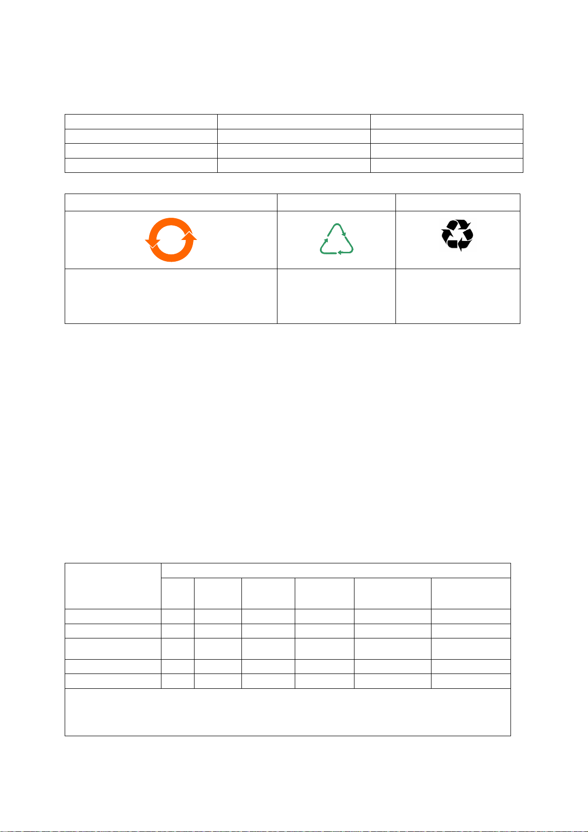
Product Label Overshipper Label Pallet Marking
2020
CBCB NWNW
Indicates toxic or hazardous substance contained
in at least one of the homogeneous materials used
for this part is above the limit requirement in
SJ/T11363-2006.
Environmental Protection Use Period is 20 years.
Recyclable Cardboard Recyclable Natural Wood
Materials Content Declaration & Environmental Protection Use Period
The Chinese regulatory requirement on the Control of Pollution Caused by Electronic Information Products No. 39
(also known as ‘China RoHS’) mandates that manufacturers of certain categories of electronic products sold in
China after 1st March 2007 –
Mark the product and packaging
Define the Product’s Environment Protection Use Period (EPUP)
Provide a Materials Content Declaration.
Environmental Protection Use Period (EPUP)
This is the period in years during which the toxic or hazardous substances or elements contained in this product
will not leak or mutate under normal operating conditions so that the use of such electronic information products
will not result in any severe environmental pollution, any bodily injury or damage to any assets.
The Environmental Protection Use Period is 20 years for this product.
For the purposes of EPUP, normal operating conditions are considered to be use in accordance with the product’s
instruction manual.
Materials Content Declaration
Toxic or Hazardous Substances and Elements
Part name Lead
(Pb) Mercury
(Hg) Cadmium
(Cd)
Hexavalent
Chromium
(Cr VI)
Polybrominated
biphenyls (PBB)
Polybrominated
diphenyl ethers
(PBDE)
Cartridge O O X XOO
Enclosure O OXXOO
Electronics and
Controls XOXXOO
Cooling system O OXXOO
Purge system O OXXOO
O: Indicates that this toxic or hazardous substance contained in all of the homogeneous materials for this
part is below the limit requirement in SJ/T11363-2006.
X: Indicates that this toxic or hazardous substance contained in at least one of the homogeneous materials
used for this part is above the limit requirement in SJ/T11363-2006.
Note 1. Table applies to all product types listed above.

This page has been intentionally left blank.

© Edwards Limited 2014. All rights reserved. Page i
Edwards and the Edwards logo are trade marks of Edwards Limited.
Contents
A546–00–880 Issue E
Contents
Section Page
1 Introduction .......................................................................................1
1.1 Scope and definitions ................................................................................................... 1
1.2 Applications ............................................................................................................... 2
1.3 The iGXL system ......................................................................................................... 2
1.4 Priority of control ........................................................................................................ 4
1.5 Active utility control .................................................................................................... 5
2 Technical Data ....................................................................................7
2.1 General technical data .................................................................................................. 7
2.2 Electrical Data ........................................................................................................... 8
2.3 Loading .................................................................................................................... 8
2.4 Connections ............................................................................................................... 9
2.5 General Data ............................................................................................................10
3 Installation ....................................................................................... 11
3.1 Locate the dry pumping system ......................................................................................12
3.2 Lubrication ...............................................................................................................13
3.3 Connect the iGX system to the vacuum/exhaust system and interstage connection (if fitted) ............13
3.4 Connect to the factory extraction system (optional) .............................................................14
3.5 Connect the nitrogen supply (if provided) ..........................................................................14
3.5.1 Flammable/pyrophoric materials ....................................................................................14
3.5.2 Gas Purges ...............................................................................................................15
3.6 Leak-test the iGX system ..............................................................................................15
3.7 Connect the electrical supply .........................................................................................16
3.8 Connect an additional RF earth (ground) (optional) ..............................................................18
3.9 Connect to the emergency stop circuit .............................................................................18
3.10 Connect the cooling water hoses .....................................................................................19
3.11 Accessories ...............................................................................................................19
3.12 Commission the iGX system ...........................................................................................20
3.13 Install additional safety equipment ..................................................................................22
4 Operation ........................................................................................ 23
4.1 Start-up ..................................................................................................................23
4.2 Status indicators ........................................................................................................24
4.3 Manual shut-down ......................................................................................................24
4.4 Automatic shut-down ..................................................................................................25
4.5 Unplanned shutdown and alarms .....................................................................................25
4.6 Emergency stop .........................................................................................................25
4.7 Restart the pump after an emergency stop or automatic shut-down ..........................................26
4.8 Single equipment monitor (SEM) .....................................................................................26
5 Maintenance ..................................................................................... 27
5.1 Safety and maintenance frequency ..................................................................................27
5.2 Relocate the system for maintenance ...............................................................................28
5.3 Draining the cooling water ............................................................................................29
5.4 Cleaning the pump ......................................................................................................30
6 Transportation, Storage and Disposal ....................................................... 31
6.1 Transportation ..........................................................................................................31
6.2 Storage ...................................................................................................................31
CG 01/14

A546–00–880 Issue E
Page ii © Edwards Limited 2014. All rights reserved.
Edwards and the Edwards logo are trade marks of Edwards Limited.
Contents
6.3 Disposal ...................................................................................................................31
7 Service, Spares and Accessories .............................................................. 33
7.1 Introduction .............................................................................................................33
7.2 Service ....................................................................................................................33
7.3 Ordering accessories ...................................................................................................34
For return of equipment, complete the HS Forms at the end of this manual.
Illustrations
Figure Page
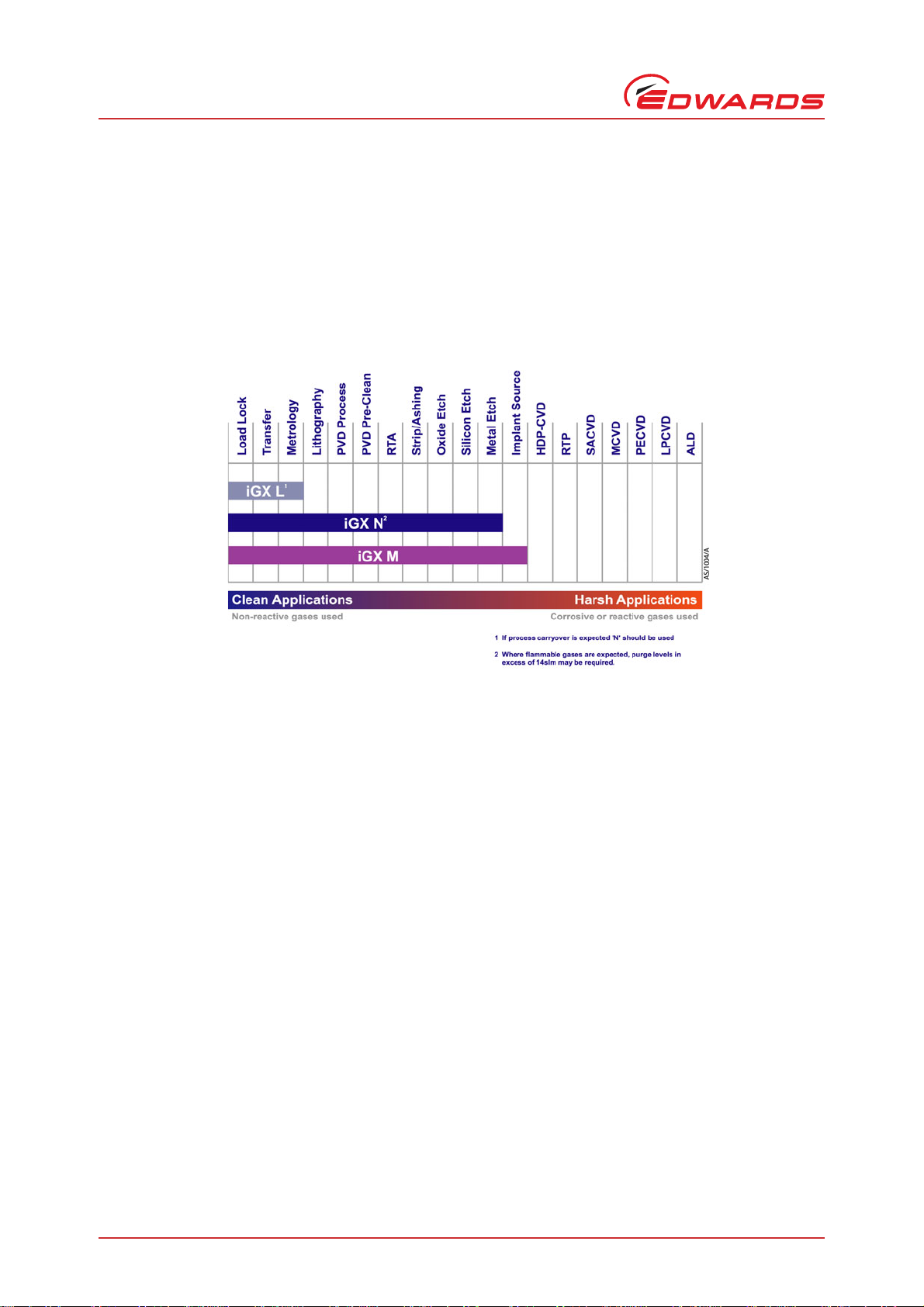
1 iGX Applications chart .................................................................................................. 2
2 The controls/connectors ................................................................................................ 3
3 The rear status panel LED indicators ................................................................................. 4
4 The front panel controls ................................................................................................ 4
5 Priority of control ........................................................................................................ 5
6 Centre of gravity and levelling foot loads ........................................................................... 8
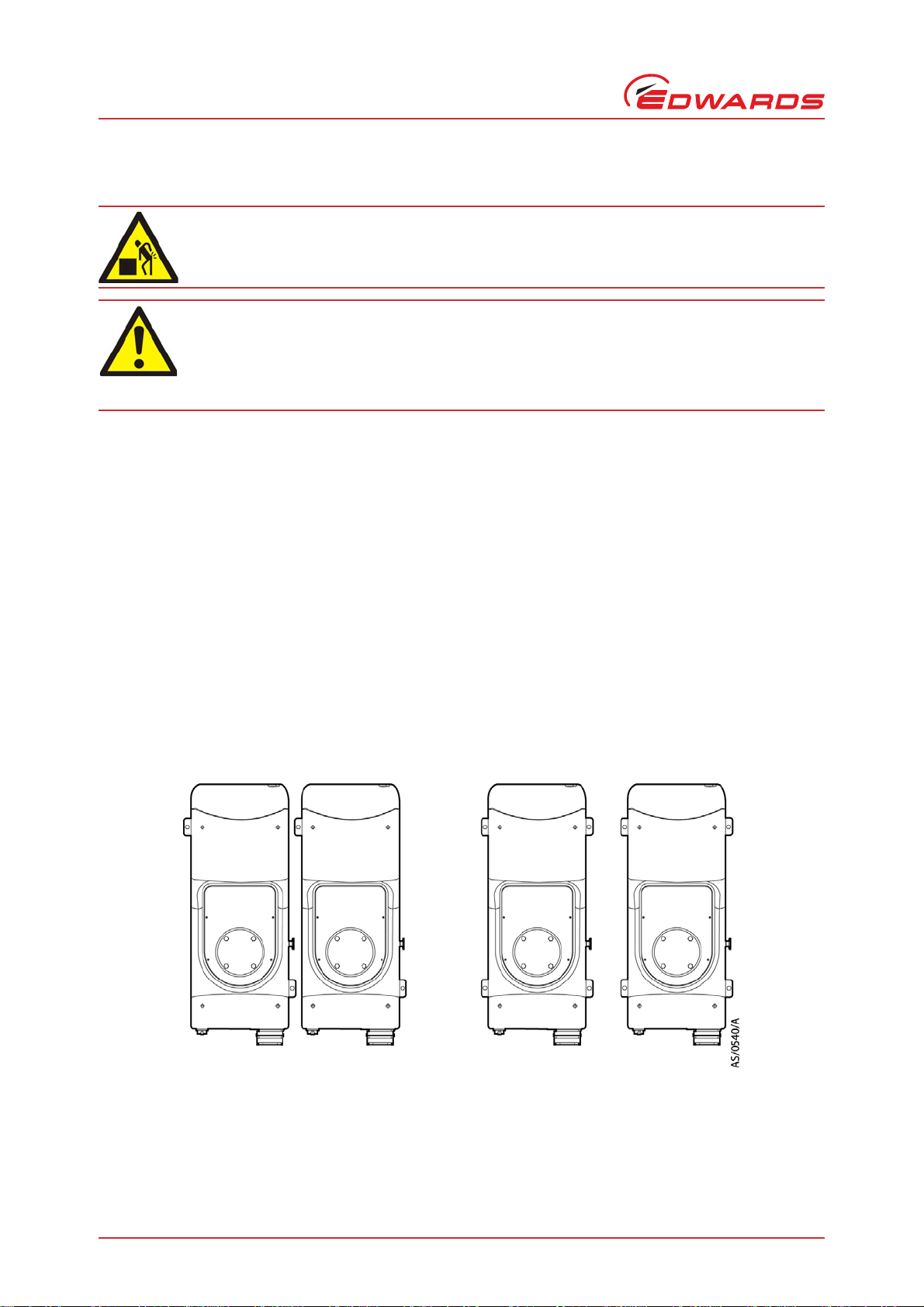
7 System arrangment to reduce effective footprint (if required) .................................................12
8 High and low volt coding pin arrangement .........................................................................17
9 Method for connecting phase wires ..................................................................................18
10 Connections to emergency stop circuit (systemable) .............................................................18
11 Installing 3/8" quick connect fittings (provided) ...................................................................20
12 Gas module access panel ..............................................................................................21
13 Flow tube (14 slm) ......................................................................................................21
14 Flow tube (4 slm) .......................................................................................................22

© Edwards Limited 2014. All rights reserved. Page iii
Edwards and the Edwards logo are trade marks of Edwards Limited.
Contents
A546–00–880 Issue E
Tables
Table Page
1 Technical data ........................................................................................................... 7
2 Technical data ........................................................................................................... 7
3 Electrical data ............................................................................................................ 8
4 Centre of gravity and levelling foot loads (Refer to Figure 6) .................................................... 8
5 iGX connector types ..................................................................................................... 9
6 Technical data ..........................................................................................................10
7 Safety sensors ...........................................................................................................25
8 Accessories ...............................................................................................................34
Associated publications
Publication title Publication number
Vacuum pump and vacuum system safety P400–40–100
Trademark credits
Fomblin®is a registered trademark of Ausimont SpA.

This page has been intentionally left blank.
A546–00–880 Issue E
Page iv © Edwards Limited 2014. All rights reserved.
Edwards and the Edwards logo are trade marks of Edwards Limited.

© Edwards Limited 2014. All rights reserved. Page 1
Edwards and the Edwards logo are trade marks of Edwards Limited.
Introduction
A546–00–880 Issue E
1Introduction
1.1 Scope and definitions
This manual provides installation, operation and maintenance instructions for the Edwards iGX dry pumping systems.
The pump must be used as specified in this manual. Read this manual before installing and operating the pump.
Important safety information is highlighted as WARNING and CAUTION instructions; these instructions must be
obeyed. The use of WARNINGS and CAUTIONS is defined below.
CAUTION
Cautions are given where failure to observe the instruction could result in damage to the equipment, associated
equipment and process.
The units used throughout this manual conform to the SI international system of units of measurement
The following warning labels are on the pump:
WARNING
Warnings are given where failure to observe the instruction could result in injury or death to
people.
Warning – refer to accompanying
documentation. Warning – risk of electric shock.
Warning – hot surfaces. Warning – moving parts present.
Warning – heavy object. Warning - pressurised.
RF earth (ground). Protective earth (ground).
Warning - use protective equipment. Warning - Risk of explosion.
A546–00–880 Issue E
Page 2 © Edwards Limited 2014. All rights reserved.
Edwards and the Edwards logo are trade marks of Edwards Limited.
Introduction
The pressurised and risk of explosion warnings only appear in this manual.
Material Safety Data Sheets for chemicals supplied by Edwards can be obtained by contacting Edwards.
1.2 Applications
If using the iGX system on an application for which it is not suitable (refer to Figure 1), the warranties may invalidate.
If in doubt, contact Edwards for advice as to the suitability of the iGX system for any particular application.
Figure 1 - iGX Applications chart
1.3 The iGXL system
Pumping a chemical that will attack the materials in contact with these process materials may, over time, result in
the internal contents of the pump becoming exposed to the external environment, which may constitute a safety
hazard. If in doubt, contact Edwards for advice as to the suitability of this pump for any particular application.
It is also a feature of this pump design that process gases are contained within the gearbox. This pump is not suitable
for use with flammable, hazardous, toxic or corrosive gases or material.
© Edwards Limited 2014. All rights reserved. Page 3
Edwards and the Edwards logo are trade marks of Edwards Limited.
Introduction
A546–00–880 Issue E
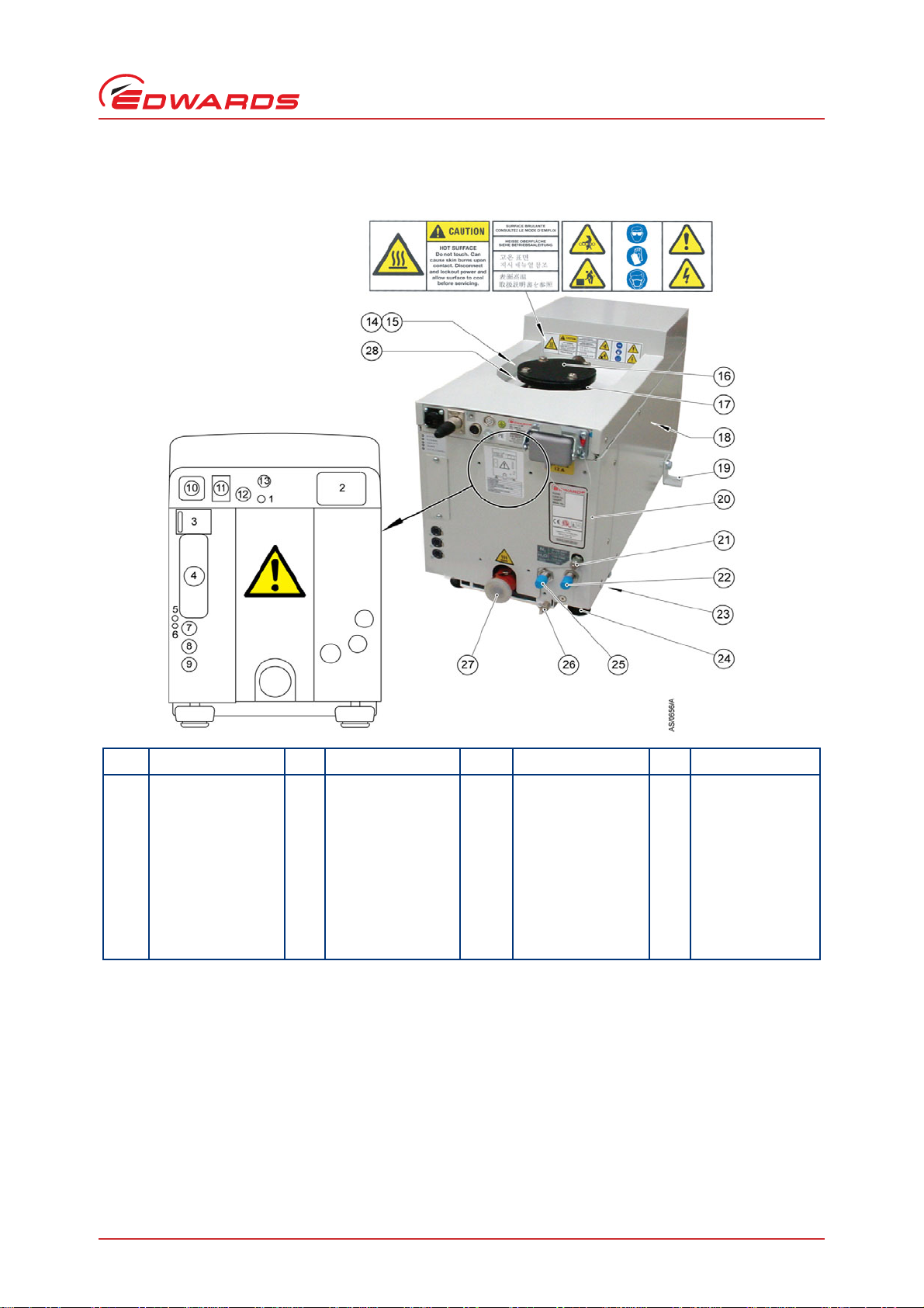
Figure 2 - The controls/connectors
Item Control/connector
identification Item Control/connector
identification Item Control/connector
identification Item Control/connector
identification
1 Protective earth (ground)
M5 8Comms2-LONmodule
connection 15 Lifting eyebolt 22 cooling water supply
connection
2 Electrical supply
connection 9 Comms 1 - System control/
PDT 2 connection 16 Pumped gas inlet
connection 23 Castors (3 off)
3 Rear status panel 10 Gate valve interface (EMO
on T variant) 17 RF earth (ground) cable 24 Levelling feet (4 off)
4 Comms 4 - MicroTIM
connection (if fitted) 11 EMS* 18 Interstage connection (if
fitted) 25 cooling water return
connection
5 Ethernet active LED 12 Accessory module
interface*
*not on T variants
19 Seismic bracket (if fitted, 4
off) 26 RF earth (ground) stud M6
6 Ethernet installed LED 13 GRC interface* 20 Gas Module access panel 27 Exhaust gas outlet
connection
7Comms3Ethernet
connection 14 Extraction port 21 Nitrogen purge port 28 Leak-test port

A546–00–880 Issue E
Page 4 © Edwards Limited 2014. All rights reserved.
Edwards and the Edwards logo are trade marks of Edwards Limited.
Introduction
Figure 3 - The rear status panel LED indicators
Figure 4 - The front panel controls
1.4 Priority of control
The iGX system can be controlled by a number of modules: the Pump Display Terminal (PDT), from the tool through
the MicroTIM, or from the front panel local control membrane (refer to Figure 4). Only one of these can have control
of the iGX system at any one time. That is, once one of these has control of the iGX system, control requests from
the other are denied.
The PDT indicates who is in control. LEDs are also provided on the rear panel, front panel or PDT, which illuminate
to indicate 'in control'. Please refer to Figure 5.
Item Indication
1 Power OK (green)
2 Running (green)
3 Warning (Amber)
4Alarm(Red)
5 Tool control (Green)
Item Indication Item Indication
1 EMS button*
*Not on T variants
6 Alarm LED (red)
2 Start button 7 Warning LED (amber)
3 Stop button 8 Running LED (green)
4 AUC LED (green) 9 Power OK LED (green)
5 Local control button/LED (green) 10 Comms 5 pump display terminal
(PDT 1) connection

© Edwards Limited 2014. All rights reserved. Page 5
Edwards and the Edwards logo are trade marks of Edwards Limited.
Introduction
A546–00–880 Issue E
1.5 Active utility control
Active Utility Control (AUC) is available on the iGX system. This function reduces the power of the iGX system while
on stand-by. The power reduction is achieved by reducing the rotational speed of the iGX pump. This function also
reduces the nitrogen purge of M variant systems while in stand-by mode.
Advanced Active Utility Control (AAUC) is also available. This function, in addition to AUC, can reduce the water flow
of the iGX system while on stand-by, therefore allowing further reductions in power. Contact Edwards for advice.
The AUC functionality is controlled by the on/off process signal from the Tool Interface Module (TIM).
Figure 5 - Priority of control
1. PDT 1
2. PDT 2
3. System controller
4. Tool
5. Front panel
6. None in control
Take
Release

A546–00–880 Issue E
Page 6 © Edwards Limited 2014. All rights reserved.
Edwards and the Edwards logo are trade marks of Edwards Limited.
This page has been intentionally left blank.

© Edwards Limited 2014. All rights reserved. Page 7
Edwards and the Edwards logo are trade marks of Edwards Limited.
Technical Data
A546–00–880 Issue E
2TechnicalData
2.1 General technical data
Table 1 - Technical data
Type Characteristics 100 300 600 1000 Units
General Dimensions (L x W x H)*
*Refer to Web for installation drawings
695 x 280
x 395 695 x 280
x 695 695 x 280
x 695 695 x 280
x 695 mm
Mass (excluding packaging) 120 200 220 230 kg
Noise level (at ultimate)†
†Check valve accessory fitted
< 60 < 55 < 55 < 55 dB(A)
Vibration level at inlet < 1.5 < 1.5 < 1.5 < 1.5 mm s-1
Vibration to the floor (when docked) < 0.05 < 0.05 < 0.05 < 0.05 mm s-1
Initial force to push the pump 0.06 0.09 0.10 0.11 kN
Sustained force to push the pump 0.04 0.06 0.07 0.07 kN
Warm up time to nominal pumping
performance 15 15 15 15 minute
s
Minimum warm up time to process gas
pumping 2222hours
Performance Typical to peak pumping speed (no gas
purge/cold pump) 100 300 600 800 m3h-1
Ultimate (shaft seal purge only) 0.005 0.0007 0.0007 0.0007 mbar
Water-cooling
system Minimum flow rate required 1 2 2 2 l min-1
Typical heat removed from the system 1 1.6 1.6 1.7 kW
Connections Pump inlet flange (bolted) ISO63 ISO63 ISO100 ISO100
Exhaust gas outlet NW25 NW25 NW25 NW25
Extraction port 50 50 50 50 mm dia
Table 2 - Technical data
Type Characteristics L N M Units
Gas system Nitrogen supply pressure range 2.5 to 6.9 2.5 to 6.9 bar gauge
Stability of supply 1.4 1.4 bar gauge
Nitrogen supply quality <0.01 <0.01 m
Nitrogen flow rate 14 44 slm
Gas module pressure 2 2 bar gauge
Pressure transducer accuracy 0.04 @ 0.41 bar gauge
Mass flow transducer accuracy 4.3 slm
Interstage (I) Peak pumping speed, interstage 25 25 m3h-1
Ultimate, interstage 0.1 0.5 mbar
Pump interstage flange NW16 NW16

A546–00–880 Issue E
Page 8 © Edwards Limited 2014. All rights reserved.
Edwards and the Edwards logo are trade marks of Edwards Limited.
Technical Data
2.2 Electrical Data
2.3 Loading
Figure 6 - Centre of gravity and levelling foot loads
Table 3 - Electrical data
Supply voltage and frequency 200/230 50/60 Hz 380/460 50/60Hz
100 300 600 1000 100 300 600 1000
Fullload(A) 122222228141414
Booster motor rating (kW) 1.9 1.9 1.9 1.9 1.9 1.9
Pump motor rating (kW) 1.9 1.9 1.9 1.9 1.9 1.9 1.9 1.9
Table 4 - Centre of gravity and levelling foot loads (Refer to Figure 6)
100 300 600 1000
Centre of gravity
A510 510 510 510
B246 266 243 243
C103 107 108 108
D216 216 216 216
E167 287 311 310
Levelling foot loads
126 45 56 56
235 58 55 55
328 43 61 61
431 54 48 48

© Edwards Limited 2014. All rights reserved. Page 9
Edwards and the Edwards logo are trade marks of Edwards Limited.
Technical Data
A546–00–880 Issue E
2.4 Connections
Table 5 - iGX connector types
Description Mating connector description/
external supply rating Internal supply rating
PDT1 XLR type 5-way plug 24 V d.c. 0.75 A
Mains connection Weidmuller HDC 16D free socket, PG21, 6
mm2
stranded wire, 13-18 mm cable OD
Ethernet connection Standard RJ45 type or Neutrik Ethercon
RJ45 IEE802.3 10BaseT Ethernet
LON module connection XLR type 4-way plug 24 V d.c. 0.75 A
PDT2 XLR type 5-way plug 24 V d.c. 0.75 A
Gate valve interface*
*Not on T variant
CPC 9-way plug, standard gender, socket
contacts 24 V d.c. (48 V peak), 100 mA
EMO (on T variant only)
6 - common and 7 - normally closed CPC 7-way plug, standard gender, socket
contacts 30 V d.c. 0.5 A
EMS* XLR type 6-way plug
External emergency stop switch
1 - supply, 2 - return 24 V d.c. 100 mA
Internal emergency stop switch
3 - common, 4 - normally open 30 V a.c. 1 A
60 V d.c. 0.55 A
Comms supply
5 - supply, 6 - return 24 V d.c. 0.5 A
Accessory module interface* Preh locking DIN 8-way plug 24 V d.c. 1.3 A
GRC interface* DIN type 6-way plug
1 - Normally open and 3 - common 30 V a.c. 1 A
2 - Normally open and 4 - normally
closed 30 V d.c. 1 A
5 - Normally open and 6 - common 60 V d.c. 0.5 A

A546–00–880 Issue E
Page 10 © Edwards Limited 2014. All rights reserved.
Edwards and the Edwards logo are trade marks of Edwards Limited.
Technical Data
2.5 General Data
Table 6 - Technical data
Item Description Rating Units
Electrical Supply voltage 3-phase 200/230 V, 50/60 Hz a.c. 380/460 V,
50/60 Hz a.c. V
Recommended fuse/isolator rating Full load current rating, refer to
Table 3.
Class CC fuse rated to 600 V.
Voltage tolerance range + 10% V
Installation category II (IEC 664)
Earth leakage 6mA
Harmonic voltage distortion factor 5%
Water-cooling system Maximum supply pressure 100 psig
Minimum supply pressure 36 psig
Minimum flow rate required Refer to Table 1 l min-1
Cooling water supply temperature
range 10 - 30 °C
Maximum particle size 0.03 mm2
Acidity 6.5 to 8.0 pH
Hardness < 100 ppm
Resistivity > 1 k cm
Solids (turbidity) < 100 ppm
Materials in contact with cooling
water Stainless steel, PTFE, copper, brass
and fluoroelastomer.
Connections Cooling water ¼” BSPT male
Nitrogen ¼” tube fitting
Materials in contact with
process gas Pump, shafts and rotors Cast SG iron, steel, aluminium
Seals PTFE and fluoroelastomer
Operating conditions Intended Use: Indoor use
Ambient temperature range:
Operating +5 to +40 °C
Storage -45 to +55 °C
Relative humidity 10 to 90 %
Maximum operating altitude 2000 m
Pollution degree 2 (IEC 61010)

© Edwards Limited 2014. All rights reserved. Page 11
Edwards and the Edwards logo are trade marks of Edwards Limited.
Installation
A546–00–880 Issue E
3 Installation
Potential hazards on the dry pumping system include electricity, hot surfaces, process chemicals, Fomblin®oil,
nitrogen and water under pressure.
Detailed safety information is given in Edwards Publication Number P400-40-100 'Vacuum Pump and Vacuum System
Safety'.
Only Edwards engineers may install the dry pumping system. Users can be trained by Edwards to conduct the
tasks described in this manual, contact the local service centre or Edwards for more information.
Do not remove the temporary cover or blanking plate from the dry pumping system inlet and exhaust until
ready to connect the dry pumping system to the vacuum or exhaust-extraction system. Do not operate the
dry pumping system unless the inlet and exhaust are connected to the vacuum and exhaust-extraction
system.
Vent and purge the process system (if the dry pumping system is to replace an existing pumping system) with
nitrogen for 15 minutes before starting installation work. Refer to Section 4.
Disconnect the other components in the process system from the electrical supply so that they cannot be
operated accidentally.
Electrical, nitrogen and water supplies are all potentially hazardous energy sources. Before carrying out any
maintenance the supply of these sources should be locked and tagged out.
Route and secure cables, hoses and pipework during installation to avoid possible trip hazards.
The pump system includes provision for ventilation extraction and secondary containment of oil and water
leaks. Any unintended overflows or spills must be removed immediately to avoid risk of slips.
Obey all national and local rules and safety regulations when installing the dry pumping system. Consult
Edwards Publication Number P400-40-100 (Vacuum Pump and Vacuum System Safety) before pumping
hazardous materials. This publication is available on request: contact the supplier or Edwards.
WARNING
Obey the safety instructions in this Section and take note of appropriate precautions. Failure to
observe these instructions may result in injury to people and damage to equipment.
WARNING
The system should not be operated with the Edwards panels removed.
A546–00–880 Issue E
Page 12 © Edwards Limited 2014. All rights reserved.
Edwards and the Edwards logo are trade marks of Edwards Limited.
Installation
3.1 Locate the dry pumping system
Use the following procedure to locate the iGX system in its operating position. The iGX system must be located on a
firm, level surface, to ensure that the system is not damaged.
1. Use suitable lifting equipment (refer to Figure 2) attached to the lifting eyebolt (15) to move the iGX system
close to its final operating position.
2. Adjust the levelling feet (24) to make sure that the iGX system is level and is not supported by the castors. The
lifting eyebolt must be retained for future use with this system.
3. If required, the iGX system can be secured to the floor by fitting suitable bolts or studs (not supplied) through
the M10 docking points on the chassis.
If vibration transmission to the floor is a concern, suitable vibration isolators (not supplied) should be fitted
between the docking points and the bolt or stud, if doing this the levelling feet will need to be removed.
4. If preferred, the lifting eyebolt can be removed and replaced with the lifting eyebolt hole plug supplied with the
systems.
5. Ensure that access is possible to the emergency stop button (refer to Figure 4, item 1), if not use an iGX
Disconnect Box (refer to Section 7.3).
Figure 7 - System arrangment to reduce effective footprint (if required)
To secure the iGX in place to prevent inadvertent movement (for example, during an earthquake), take note of the
following:
The iGX system seismic brackets (Figure 2, item 19) are designed to withstand a level 4 earthquake in a
ground floor installation.
WARNING
Use suitable lifting equipment to move the system. It is too heavy to lift by hand.
WARNING
Do not exceed the topple angle of 10 ° when moving the pump. Wheel the system on its castors to
move it into its operating position. The system should only be wheeled short distances over flat
surfaces. If the floor surface is uneven or has obstacles the system should be lifted with suitable
lifting equipment.
This manual suits for next models
53
Other Edwards Laboratory Equipment manuals


