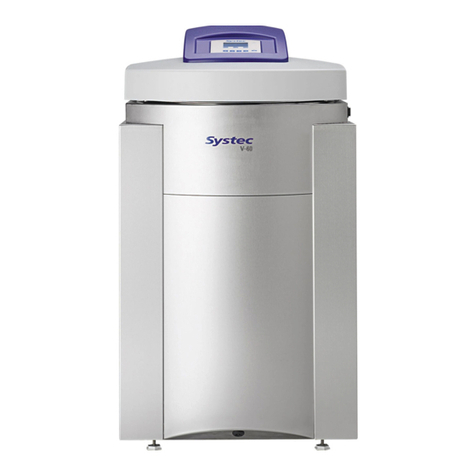
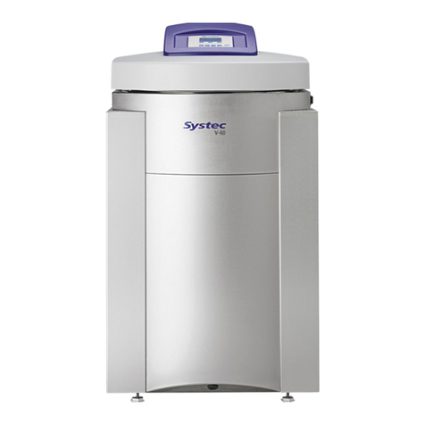
Systec V Series User manual

S
ERVICE
M
ANUAL
S
YSTEC
V/D
S
ERIES
0
51
-X
V
051
-XD
Systec GmbH
Konrad-Adenauer-Straße 15
D-35440 Linden, Germany
Tel.: +49(0)6403 67070-0
Fax.: +49(0)6403 67070-222
01.01.2015
Revision: 2.1


V/D
S
ERIES
0
Revision: 2.1
C
ONTENTS
Only for authorised service personnel!
The service and maintenance tasks described in this manual
may only be carried out by authorised service personnel.
Notes on the documentation 1
Commissioning 2
Mechanical assemblies 3
Electrical assemblies 4
Regular tests and maintenance 5
Service software 6
Troubleshooting 7
Parameters 8
Appendix:
Maintenance checklist 9


V/D
S
ERIES
1
Revision: 2.1 1-1
1 N
OTES ON THE DOCUMENTATION
Aim of this chapter
This chapter contains notes on the documentation and important safety
information.
Contents
1.1 Notes on the documentation................................................... 2
1.1.1
Associated documents................................................................................. 2
1.1.2
Type plates .................................................................................................. 2
1.1.3
Display texts ................................................................................................ 2
1.1.4
Validity of the chapters ................................................................................ 2
1.2 Safety instructions .................................................................. 3
1.3 Warning instructions and safety signs .................................... 3
1.4 Supplementary instructions .................................................... 3
1.5 Service notes.......................................................................... 4

V/D
S
ERIES
N
OTES ON THE DOCUMENTATION
1-2 Revision: 2.1
1.1 Notes on the documentation
1.1.1 Associated documents
The following documents apply in conjunction with this service manual:
−Records documenting installation, commissioning and instruction
−Service report
−Logbook (see operating manual, chapter 11, “Logbook”)
−Maintenance checklist
−Operating manual
1.1.2 Type plates
The type plates are factory fitted in the following locations:
Device Pressure chamber
V series Right side Front
D series Left side Right side
D-23 Rear, right Rear side
1.1.3 Display texts
The display texts are shown in English in this service manual.
1.1.4 Validity of the chapters
When necessary, a table at the start of the chapter indicates for which
devices the chapter applies.
Example:
V-40 – 55 V-65 – 150 X E B
D-23 D-45 D-65 – 200 X
= valid
= optional
Explanation of example: The information contained in this chapter applies
to all V and D devices in the X series, and is optional for the E series.

V/D
S
ERIES
N
OTES ON THE DOCUMENTATION
Revision: 2.1 1-3
1.2 Safety instructions
−Observe the safety instructions in the operating manual.
−Failure to do so can result in damage to the device, fire or other
hazards.
−Components may only be serviced or replaced by authorised service
engineers.
−Before any work on the device, isolate it and prevent it from being
switched on again. Pay attention to all circuit breakers, as these carry
dangerous high voltages.
−When working on the device, avoid contact with parts which move
automatically.
1.3 Warning instructions and safety signs
In addition to the basic and specific safety instructions, risks can arise
through dangerous working procedures.
These procedures are indicated as follows:
Warning
These points warn of a danger of serious or fatal injuries.
Instructions on preventing the danger must be followed. A
safety sign corresponding to the particular type of danger gives
an additional warning.
Attention
These points refer to possible material damage.
Follow the instructions exactly to prevent incorrect operation
or destruction of the device.
1.4 Supplementary instructions
In addition to the basic procedures, there are possible variations which are
indicated as follows:
Special instructions
These points provide information on additional or alternative
procedures that are possible under certain circumstances,
for example.

V/D
S
ERIES
N
OTES ON THE DOCUMENTATION
1-4 Revision: 2.1
1.5 Service notes
Pay attention to the following points when handling Teflon hoses and
screw connections:
−Do not kink the hoses.
−Avoid excess mechanical strain on the Teflon hoses.
−When reconnecting, push the hoses completely onto the fittings and
tighten the lock-nuts up to the stop.
−If white stress marks can be seen on a hose, replace it – white marks
on Teflon hoses indicate damages.
−When shortening hoses, cut at right angles using a sharp knife (do not
pinch off or crimp using side cutters or similar tools).

V/D
S
ERIES
2
Revision: 2.1 2-1
2 C
OMMISSIONING
Aim of this chapter
This chapter describes the steps for commissioning the device at the
operator's premises, from installation through staff instruction up to
handover of the logbook.
Contents
2.1 Preparing for commissioning.................................................. 3
2.1.1
Unpacking and setting up the device .......................................................... 3
D-23, D-45................................................................................................... 3
D-65 – D-200............................................................................................... 3
V series........................................................................................................ 4
2.1.2
Scope of delivery......................................................................................... 5
2.1.3
Setting up the device................................................................................... 5
2.1.4
Cleaning the surfaces.................................................................................. 5
2.2 Device connections................................................................. 6
2.2.1
VX/VE 40 – 150........................................................................................... 6
2.2.2
VB 40 – 150................................................................................................. 7
2.2.3
DX-23, DE-23 with automatic demineralised water supply option .............. 8
2.2.4
DE-23........................................................................................................... 9
2.2.5
DB-23......................................................................................................... 10
2.2.6
DX/DE-45 .................................................................................................. 11
2.2.7
DB-45......................................................................................................... 12
2.2.8
DX/DE-65 – 200 ........................................................................................ 13
2.2.9
DB-65 – 200 .............................................................................................. 14
2.3 Electrical connection............................................................. 15
2.4 Water supply......................................................................... 15
2.4.1
Testing the water quality............................................................................ 15
2.4.2
Connecting the cooling water supply (X and E series).............................. 15
2.4.3
Connecting the demineralised water supply ............................................. 16
2.4.4
Connecting the drain ................................................................................. 16
2.5 Connecting the compressed air supply................................. 16
2.6 Setting the normal pressure at the installation location......... 16
2.7 Switching the device on and off............................................ 17

V/D
S
ERIES
C
OMMISSIONING
2-2 Revision: 2.1
2.8 Performing a test run............................................................ 17
2.9 Setting parameters ............................................................... 17
2.10 Instructing the operating personnel....................................... 18
2.10.1
Supply connections ................................................................................... 18
2.10.2
Loading the device .................................................................................... 18
2.10.3
Using menus.............................................................................................. 18
2.10.4
Recognising error messages..................................................................... 18
2.10.5
Documentation software (optional)............................................................ 18
2.10.6
Changing the print intervals....................................................................... 19
2.11 Reference............................................................................. 19
Diagrams
Fig. 1: Transport with sack truck.......................................................... 4
Fig. 2: Device connections for VX/VE 40 – 150................................... 6
Fig. 3: Device connections for VB 40 – 150......................................... 7
Fig. 4: Device connections on rear of DX-23, DE-23 with automatic
demineralised water supply option............................................ 8
Fig. 5: Device connections on rear of DE-23 ....................................... 9
Fig. 6: Device connections on DB-23................................................. 10
Fig. 7: Device connections on rear of DX/DE-45 ............................... 11
Fig. 8: Device connections on DB-45................................................. 12
Fig. 9: Device connections on rear of DX/DE-65 – 200 ..................... 13
Fig. 10:Device connections on DB-65 – 200....................................... 14
Tables
Tab. 1: Quality requirements for the water used................................. 15

V/D
S
ERIES
C
OMMISSIONING
Revision: 2.1 2-3
2.1 Preparing for commissioning
2.1.1 Unpacking and setting up the device
D-23, D-45
The device should always be unpacked and set up by two
people!
Because of its size and weight, we recommend that two people
unpack and set up the device.
D-65 – D-200
The device
should always be unpacked and set up by four
people!
Because of its size and weight, we recommend that four people
unpack and set up the device.
The device is delivered in its transport packaging on a pallet.
•Remove the transport packaging.
Only lif
t the device by its base frame! Always wear safety
gloves!
Only lift the device by its base frame, not by the handles or the
recessed grips in the door. Wear safety gloves to avoid injuries
caused by sharp edges.
•Dispose of the pallet and the transport packaging in accordance with
national regulations.

V/D
S
ERIES
C
OMMISSIONING
2-4 Revision: 2.1
V series
The device should always be unpacked and set up by two
people!
Because of its size and weight, we recommend that two people
unpack and set up the device.
051
-
X
V
Fig. 1: Transport with sack truck
•Push the transport equipment (e.g. sack truck) under the left side of the
device.
Danger of damage to hoses!
There are hoses underneath the right side of the device which
may be damaged if care is not taken.

V/D
S
ERIES
C
OMMISSIONING
Revision: 2.1 2-5
2.1.2 Scope of delivery
−Device
−Operating manual
−Hoses (according to available device connections)
−Accessories (according to delivery note)
Note
Some accessories are located in the sterilisation chamber.
•Check that the scope of delivery is complete and undamaged.
2.1.3 Setting up the device
•Set up the device at the position where it will be used and align it with a
spirit level.
Separate assembly instructions for pass
-
through
autoclaves!
Pay attention to the corresponding assembly instructions when
setting up pass-through autoclaves.
2.1.4 Cleaning the surfaces
•If necessary, clean the outer surface of the housing.

V/D
S
ERIES
C
OMMISSIONING
2-6 Revision: 2.1
2.2 Device connections
2.2.1 VX/VE 40 – 150
Fig. 2: Device connections for VX/VE 40 – 150
1 Serial interface (RS-232 for connection to a PC)
2 Mains connection (3 phase, 380 – 400 V + N + PE)
3 Vacuum pump fuse
4 Compressor fuse
5 Water pump fuse
6 Safety temperature limiter (STL)
7 Compressed air (7.2 mm quick release connector, optional)
8 Demineralised water (3/4") outer thread, pressure > 1 bar
9 Cooling water (3/4") outer thread, pressure > 1 bar
10 Waste water (3/4") outer thread (drain provided by customer temperature-
resistant to 103 °C)

V/D
S
ERIES
C
OMMISSIONING
Revision: 2.1 2-7
2.2.2 VB 40 – 150
1
2
3
4
5
6
Fig. 3: Device connections for VB 40 – 150
1 Mains connection:
– VB 65 – VB 150: 3 phase, 380 – 400 V + N + PE;
– VB 40, VB 55: 230 V/50Hz
2 Inside-air fan fuse
3 Vacuum pump fuse
4 Compressor fuse
5 Safety temperature limiter (STL)
6 Waste water (3/4") outer thread (drain provided by customer temperature-
resistant to 103 °C)

V/D
S
ERIES
C
OMMISSIONING
2-8 Revision: 2.1
2.2.3 DX-23, DE-23 with automatic demineralised water supply option
A
A
5 6 7
1 3 42
9
8
10
11
12
13
Fig. 4: Device connections on rear of DX-23, DE-23 with automatic
demineralised water supply option
1 Drain connection on steam generator
2 Waste water (3/4") outer thread (drain provided by customer temperature-
resistant to 103 °C)
3 Cooling water (3/4") outer thread, pressure > 1 bar
4 Demineralised water (3/4") outer thread, pressure > 1 bar, optional
5 Compressed air (7.2 mm quick release connector), optional
6 Steam generator safety valve (DX devices only)
7 Safety valve on sterilisation chamber
8 Drain on demineralised water reservoir container
9 Drainage tap for reservoir container
10 Serial interface (RS-232 for connection to a PC)
11 Safety temperature limiter (STL)
12 Connection for Aquastop
13 Mains connection (230 V, 50/60 Hz)

V/D
S
ERIES
C
OMMISSIONING
Revision: 2.1 2-9
2.2.4 DE-23
A
A
5
1 3 42
7
6
9
8
10
Fig. 5: Device connections on rear of DE-23
1 Change-over valve for demineralised water (recirculate or drain)
2 Cooling water (3/4") outer thread, pressure > 1 bar
3 Waste water (3/4") outer thread (drain provided by customer temperature-
resistant to 103 °C)
4 Compressed air (7.2 mm quick release connector), optional
5 Safety valve on sterilisation chamber
6 Drain on demineralised water reservoir container
7 Drainage tap for reservoir container
8 Serial interface (RS-232 for connection to a PC)
9 Safety temperature limiter (STL)
10 Mains connection (230 V, 50/60 Hz)

V/D
S
ERIES
C
OMMISSIONING
2-10 Revision: 2.1
2.2.5 DB-23
A
A
1 2 4
3
5
6
7
Fig. 6: Device connections on DB-23
1 Change-over valve for demineralised water (recirculate or drain)
2 Waste water (3/4") outer thread (drain provided by customer temperature-
resistant to 103 °C)
3 Drain on demineralised water reservoir container
4 Safety valve on sterilisation chamber
5 Drainage tap for reservoir container
6 Safety temperature limiter (STL)
7 Mains connection (230 V, 50/60 Hz)

V/D
S
ERIES
C
OMMISSIONING
Revision: 2.1 2-11
2.2.6 DX/DE-45
1 3 4 5 62 7 8
9
10
11
12
13
Fig. 7: Device connections on rear of DX/DE-45
1 Cooling water (3/4") outer thread, pressure > 1 bar
2 Demineralised water (3/4") outer thread, pressure > 1 bar, optional
3 Compressed air (7.2 mm quick release connector), optional
4 Drain on demineralised water reservoir container
5 Waste water (3/4") outer thread (drain provided by customer temperature-
resistant to 103 °C)
6 Mains connection (230 V, 50/60 Hz)
7 Connection for Aquastop, optional
8 Serial interface (RS-232 for connection to a PC)
9 Fan fuse (optional)
10 Vacuum pump fuse (optional)
11 Demineralised water fuse
12 Compressor fuse
13 Safety temperature limiter (STL)

V/D
S
ERIES
C
OMMISSIONING
2-12 Revision: 2.1
2.2.7 DB-45
1 2 3
4
5
6
7
Fig. 8: Device connections on DB-45
1 Drain on demineralised water reservoir container
2 Waste water (3/4") outer thread (drain provided by customer temperature-
resistant to 103 °C)
3 Mains connection (230 V, 50/60 Hz)
4 Inside-air fan fuse
5 Demineralised water fuse
6 Compressor fuse
7 Safety temperature limiter (STL)
This manual suits for next models
18
Table of contents
Other Systec Laboratory Equipment manuals