Edwards LaserSense HSSD-2 User manual

LaserSense HSSD-2
A
spirating Smoke Detector
Installers Handbook
P/N 9-14565 (EN) • REV 02 • ISS 11ABR13

Copyright © 2013 UTC Fire and Security. All rights reserved.
Manufacture
r
Kidde Products Limited
Unit 2, Blair Way, Dawdon
Seaham, County Durham
SR7 7PP
United Kingdom
Certification 0832.
0832-CPD-1076 (Standard detector)
0832-CPD-1077 (Command module detector)
0832-CPD-1078 (Minimum display detector)
EN 54-20: 2006
Aspirating smoke detectors for fire detection and fire alarm systems
for buildings.
Class A, B, and C
Technical data: See INF48022 and INF48023 held by the
manufacturer.
Contact information For contact information, see www.airsensetechnology.com.

LaserSense HSSD-2 Aspirating Smoke Detector Installers Handbook i
Content
Important information iii
EN 54-20 compliance v
Chapter 1 Product and component descriptions 1
Introduction 2
Available software for the detector
2
Specifications 3
Standard detector 4
Stand-alone command module or command module detector 6
Standard detector interior view 7
Stand-alone command module interior view 8
Command module detector interior view 9
Detector controls and indicators 10
Display types 11
Chapter 2 Installation and assembly 13
Introduction 14
Antistatic precautions 15
General installation guidelines 15
System design 17
Mechanical installation 19
Electrical installation 22
Power supply connections 28
Demonstration mode 29
Interfacing with fire alarm panels 30
Connecting a command module to an addressable fire
panel 33
Connecting a single detector to an addressable fire panel 35
Connecting to a PC 35
Chapter 3 Programming the unit 37
Introduction 38
Entering programming mode 39
Main menu 40
Navigating through the menus 40
Detector programmable functions 42
Chapter 4 Commissioning 57
Introduction 58
Commissioning 58
Precommissioning preparation 59
Acclimation period 59
Transport time verification 60
Gross smoke testing 60

ii LaserSense HSSD-2 Aspirating Smoke Detector Installers Handbook
Chapter 5 Troubleshooting 63
Troubleshooting the detector 64
Error messages 66
Chapter 6 Maintenance 67
Introduction 68
Scheduled maintenance 68
Maintenance procedures 69
Appendix A External communications 73
Glossary 77
Index 79

LaserSense HSSD-2 Aspirating Smoke Detector Installers Handbook iii
Important information
Regulatory information
This equipment is Class III as defined in EN 60950 (i.e., this equipment is
designed to operate from Safety Extra Low Voltages and does not generate any
hazardous voltages).
As this equipment is part of a fire detection system, input power should be
supplied from an approved power supply conforming to EN 54-4 or UL/ULC and
FM standards.
In order for the installation to conform to EN 54-20, pipes must conform at least
to EN 61386-1 Class 1131.
This product has been designed to meet the following requirements:
• NFPA 72 National Fire Alarm and Signaling Code
• UL 268 Smoke Detectors for Fire Alarm Signaling Systems
• UL 268A Smoke Detectors for Duct Applications
• UL 864 Control Units for Fire Protective Signaling Systems
• CAN/ULC-S524 Installation of Fire Alarm Systems
• ULC-S527 Control Units for Fire Alarm Systems
• CAN/ULC-S529 Smoke Detectors for Fire Alarm Systems
System reacceptance test after reprogramming (UL/ULC and FM): To ensure
proper system operation, this system must be retested in accordance with
NFPA 72 after any programming change. Reacceptance testing is also required
after any addition or deletion of system components, and after any modification,
repair, or adjustment to system hardware or wiring.
Limitation of liability
To the maximum extent permitted by applicable law, in no event will UTCFS be
liable for any lost profits or business opportunities, loss of use, business
interruption, loss of data, or any other indirect, special, incidental, or
consequential damages under any theory of liability, whether based in contract,
tort, negligence, product liability, or otherwise. Because some jurisdictions do not
allow the exclusion or limitation of liability for consequential or incidental
damages the preceding limitation may not apply to you. In any event the total
liability of UTCFS shall not exceed the purchase price of the product. The
foregoing limitation will apply to the maximum extent permitted by applicable law,
regardless of whether UTCFS has been advised of the possibility of such
damages and regardless of whether any remedy fails of its essential purpose.
Installation in accordance with this manual, applicable codes, and the instructions
of the authority having jurisdiction is mandatory.
While every precaution has been taken during the preparation of this manual to
ensure the accuracy of its contents, UTCFS assumes no responsibility for errors
or omissions.

iv LaserSense HSSD-2 Aspirating Smoke Detector Installers Handbook
Advisory messages
Advisory messages alert you to conditions or practices that can cause unwanted
results. The advisory messages used in this document are shown and described
below.
WARNING: Warning messages advise you of hazards that could result in injury
or loss of life. They tell you which actions to take or to avoid in order to prevent
the injury or loss of life.
Caution: Caution messages advise you of possible equipment damage. They tell
you which actions to take or to avoid in order to prevent the damage.
Note: Note messages advise you of the possible loss of time or effort. They
describe how to avoid the loss. Notes are also used to point out important
information that you should read.
Product Symbols
This symbol appears on the main board of the unit and indicates that the
board contains static sensitive components.
This label is located on the laser chamber at the bottom right of the open
detector and signifies that the unit is a Class 1 Laser product as specified
in IEC 60825-1. The unit incorporates a Class 3B embedded laser which
must not be removed from the detector, as retinal damage may result if
the laser beam enters the eye.
This symbol indicates the Safety ground studs. These are for grounding
cable screens, etc., and should not be connected to 0V or signal earth.

LaserSense HSSD-2 Aspirating Smoke Detector Installers Handbook v
EN 54-20 compliance
The installation must be designed using PipeCAD software, which is provided
free on the CD shipped with each detector. After designing the installation
including pipes, endcaps, and sampling holes, enter the detector type. To select
the detector type, select Options, select Calculation options, and then select the
detector from the Type drop-down list.
Select Options > Calculate, or click on the calculator icon. The software will
prompt you to choose from Use set hole sizes, Best flow balance, or Max.
permissible transit time. Select the appropriate option, and then click OK. The
results for each pipe (View > Results) show calculations for each sampling hole
on the pipe with the nearest to the detector at the top of the screen, and the
endcap hole at the bottom.
For EN 54-20 compliance the transport time of the last sampling hole shall be
checked following all installation and proven to be less than or equal to that
determined by PipeCAD.
The classification of each sampling device configuration and associated
sensitivity settings are determined by the column headed Hole sensitivity %
obs/m which shows the predicted sensitivity for each hole. For the installation to
comply with EN 54-20 depending on the class of installation, each sampling hole
must be no less sensitive than the following:
Class A: 0.62% obs/m
Class B: 1.95% obs/m
Class C: 4.65% obs/m
The calculation can be further refined by leaving a working detector in the
protected area for at least 24hrs at the intended alarm factor for the installation
(this could be done before or after installation). The detector sensitivity can be
read from the “Sensitivity” figure on the histogram screen of the Remote software
supplied with each detector. Click Options > Calculation options to open the
Hole calculation options dialog box. Enter the sensitivity value obtained from the
practical test, and then click OK. The new calculated value will use the real
sensitivity from the practical test.
The PipeCAD software will determine the classification of any used configuration.
Commissioning and periodic system tests must involve smoke tests to verify that
the system performs as expected and enters Fire (Alarm) 1 alarm within the time
determined by PipeCAD from the farthest hole. The detector sensitivity must also
be inspected to ensure it has not radically fallen from the installed figure. If it has
changed for any reason, the new figure must be re-entered into PipeCAD and the
recalculated hole sensitivities must be confirmed to be within the class limits
shown above.

vi LaserSense HSSD-2 Aspirating Smoke Detector Installers Handbook
The settings of a compliant system should be recorded, as it is possible by
changing certain programmable functions to make the system non-compliant. If
functions are changed, it is recommended that the system is retested if
continuing compliance is in any doubt.
Note: For EN 54-20 compliant installations the detector requires that the flow
thresholds be set manually to ± 6% of the nominal value, after the FastLearn
phase is completed. For example, if the flow rate is 64% after the completion of
the FastLearn period, the user must manually set the low flow threshold to 58%
and the high flow threshold to 70%.

LaserSense HSSD-2 Aspirating Smoke Detector Installers Handbook 1
Chapter 1
Product and component
descriptions
Summary
This chapter provides descriptions of the detector features, specifications, and
controls and indicators.
Content
Introduction 2
Available software for the detector
2
Specifications 3
Standard detector 4
Stand-alone command module or command module detector 6
Standard detector interior view 7
Stand-alone command module interior view 8
Command module detector interior view 9
Detector controls and indicators 10
Display types 11

Chapter 1: Product and component descriptions
2 LaserSense HSSD-2 Aspirating Smoke Detector Installers Handbook
Introduction
The detector is a highly sophisticated “next generation” high sensitivity aspirating
smoke detection product that provides all the benefits of air sampling high
sensitivity smoke detection, including very early warning. Designed for easy
installation and commissioning, the detector incorporates a patented “artificial
intelligence” known as ClassiFire, which allows the detector to configure itself to
optimum sensitivity, alarm thresholds, and minimum nuisance alarms for various
environments.
The detector operates by drawing air from a protected space via a supervised
piping network in relatively small areas. The sampled air is passed through a
dust separator (filter) to remove dust and dirt before entering the laser detection
chamber. State-of-the-art electronics are used to analyse the sampled air and
generate a signal representing the level of smoke present.
ClassiFire intelligence also monitors the detector chamber and dust separator
for contamination, continually adjusting the appropriate operating parameters to
counteract the negative effects of any contamination. Aspirating smoke detectors
are unique in being able to provide a consistent level of protection in a very wide
range of environments by continuously making minor adjustments to sensitivity.
The aspirating line of detectors detects “difficult-to-detect” slow growth electrical
overload incipient fires in “difficult” environments.
Available software for the detector
The Remote Control and the SenseNET software packages are available for use
with the detector:
• Remote Control software: Provided free of charge with every detector, this
software package enables the user to set up and configure the programmable
functions of one or more detectors or Command Module from a computer
connected via an RS-232 serial cable.
• SenseNET software: SenseNET software is used to configure and manage a
large network of detectors with a simple, streamlined graphical user interface
from a computer connected to a detector or Command Module via an RS-232
serial cable to RS-485 converter interface.

Chapter 1: Product and component descriptions
LaserSense HSSD-2 Aspirating Smoke Detector Installers Handbook 3
Specifications
Caution: This equipment is only to be used in accordance with this specification.
Failure to operate the equipment as specified may cause damage to the unit,
injury, or property damage.
Specification Value
SELV rating (EN 60950) Class III
Supply voltage 21.6 to 26.4 VDC
PSU Type: conforming to EN 54-4. Electrical safety
complies with IEC 61010-1
Size 427 × 372 × 95 mm (16.8 × 14.6 × 3.7 in.)
Weight
Detector
Command module detector
Stand-alone command module
Stand-alone command module and
batteries
5.2 kg (11.5 lb.)
5.3 kg (11.6 lb.)
6.2 kg (13.6 lb.)
10.1 kg (22.3 lb.)
Operating temperature range −10 to +60ºC (EN 54-20)
32 to 100°F (0 to 38°C) (UL 268, CAN/ULC-S529,
FM)
Operating humidity range 0 to 90% noncondensing
IEC 61010-1 Pollution degree 1
IEC 61010-1 Installation Cat. II
Sensitivity range
(%obs/m)
(%obs/ft.)
Min. = 25%, Max. = 0.03% FSD
Min. = 7.62%, Max. = 0.00914% FSD
Maximum sensitivity resolution 0.0015% obs/m (0.00046% obs/ft.)
Detection principle Laser light scattering mass detection
Particle sensitivity range 0.0003 to 10 microns
Current consumption
Detector
Stand-alone command module
Command module detector
300 mA (fan speed 1)
470 mA (fan speed 8)
750 mA (fan speed 16)
450 mA
750 mA (fan speed 1)
920 mA (fan speed 8)
1.5 A (fan speed 16)
Relay contact rating 500 mA at 30 VDC
Maximum sampling pipe length 200 m (656 ft. total)
Sampling pipe inlets 4
Maximum number of sampling holes 25 per pipe (100 total)
Sampling pipe internal diameter 3/4 in. (ID) or 27 mm (OD)
Alarm levels 4 (Fire (Alarm) 2, Fire (Alarm) 1, Pre-Alarm and Aux)

Chapter 1: Product and component descriptions
4 LaserSense HSSD-2 Aspirating Smoke Detector Installers Handbook
Specification Value
Bar graph sensitivity range 0.0015 to 25% obs/m (0.00046 to 7.62 obs/ft.)
Bar graph segments 26
Chamber service intervals Greater than 8 years (depending on environment)
Dust separator (filter) replacement
intervals
Greater than 5 years (depending on environment)
Laser lifetime (MTTF) Greater than 1000 years
Programming Front panel or PC via RS-232/RS-485
Data bus cable RS-485 data cable
Data bus length 1,200 m (4,000 ft.)
IP rating IP50
Standard detector
The standard detector may be operated as a stand-alone unit, or may be part of
a network of detectors centrally monitored by a command module. It may be
programmed via its front panel, as in the standard detector and command
module versions, shown in Figure 2 on page 5 and Figure 3 on page 6.
Alternatively, the standard detector can be ordered without a front panel display
(minimum display) as shown in Figure 1 on page 5. The detectors may be
programmed remotely via the detector’s RS-485 terminals using a command
module, or via the detector’s RS-232 port using a PC running the Remote Control
software. A copy of this software is supplied with each detector.
The standard detector without a front panel display is housed in a rugged sheet
metal steel enclosure. This detector includes LEDs to indicate alarms, faults, and
normal operating conditions. The standard detector with display (and command
module) can also be ordered with the steel enclosure.
Chapter 1: Product and component descriptions
LaserSense HSSD-2 Aspirating Smoke Detector Installers Handbook 5
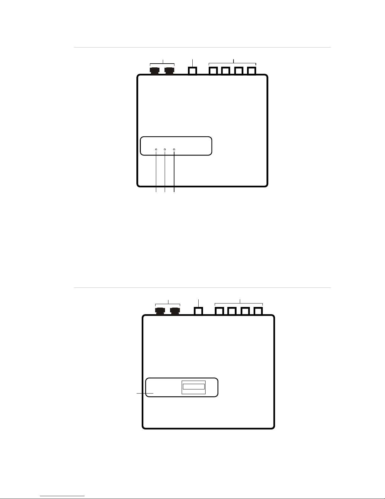
Figure
1
: Minimum display detector
(
2
)
(
3
)
(
4
)
(
1
)
(
5
)
(
6
)
(1) Cable glands
(2)
Exhaust port
(3) Sampling ports
(4) Alarm LED: Illuminates when the alarm
level has been reached and the
appropriate time delays have expired.
(5) Fault LED: Illuminates when the unit has
a fault and a fault signal is being sent to
the fire alarm panel.
(6) OK LED: Illuminates to show normal
operation when there are no faults. The
OK lamp will flash during the 15-minute
FastLearn period when the detector is
first learning about its environment.
Figure
2
: Standard detector
(2) (3)
(4)
(1)
(1) Cable glands
(2)
Exhaust port
(3)
Sampling ports
(4)
Front panel display

Chapter 1: Product and component descriptions
6 LaserSense HSSD-2 Aspirating Smoke Detector Installers Handbook
Stand-alone command module or command
module detector
When multiple detectors are networked together, a command module may be
used to tie all the detectors together and to provide a centralized point for
network access and programming, running diagnostics, and PC and fire panel
connection.
The command module can be mounted either inside a detector or as a stand-
alone unit in its own housing without an aspirator or smoke detection circuitry. If
detectors attached to the Command Module are mounted in different fire zones
then the Command Module must be mounted in its own housing with separate
power supply to comply with BS5839 and EN 54.
When a command module is mounted inside a detector, the Standard detector
display is replaced with a dedicated command module display. The programming
buttons and display on the front of the detector belong to the command module.
Programming at the command module is very similar to programming a detector,
the main difference being that the command module has extra functions to
control all the aspirating detectors connected in the network.
Figure
3
: Command module detector
(4)
(
2
)
(
3
)
(
1
)
(1) Cable glands
(2)
Exhaust port
(3)
Sampling ports
(4)
Front panel display

Chapter 1: Product and component descriptions
LaserSense HSSD-2 Aspirating Smoke Detector Installers Handbook 7
Standard detector interior view
Figure
4
: Standard detector interior view
(10)
(5)
(7)
(
3
)
(8)
(4)
(9)
(6)
(
2
)
(
1
)
(1)
RS-232
serial
port
(2)
Safety earth studs
(3)
1 A 5 x 20mm T-type protection fuse
(4) Dust separator (filter) removal handle
(5) Detector address DIP switch
(6)
Front panel display connectors
(7)
Display attachment screws
(8)
24 VDC power supply connections
(9)
RS-485 terminal connections
(10)
Terminal block connections

Chapter 1: Product and component descriptions
8 LaserSense HSSD-2 Aspirating Smoke Detector Installers Handbook
Stand-alone command module interior view
Figure
5
: Stand-alone command module interior view
(1) (2) (3) (4)
(5)
(6)
(7)
(1)
RS-232
serial
port
(2)
Safety earth studs
(3) 24 VDC power supply connections
(4)
500 mA 5 x 20mm T-type protection fuse
(5) Front panel display connectors
(6) Display attachment screws
(7) Terminal block connections

Chapter 1: Product and component descriptions
LaserSense HSSD-2 Aspirating Smoke Detector Installers Handbook 9
Command module detector interior view
Figure
6
: Command module detector interior view
(
1
)
(
2
)
(3)(4)(5)
(6)
(7)
(8)
(9)
(10)
(11)
(1)
RS-232
serial
port
(2)
Safety earth studs
(3) Dust separator (filter removal handle
(4)
Detector display connection
(5) Detector address DIP switches
(6) Command module display connection
(7) Display attachment screws
(8) Command module CPU board
(9) Command module CPU board -
terminal block connections
(10) Detector CPU board
(11) Detector CPU board - terminal block
connections

Chapter 1: Product and component descriptions
10 LaserSense HSSD-2 Aspirating Smoke Detector Installers Handbook
Detector controls and indicators
The standard detector and the command module detector controls and indicators
are very similar.
Figure
7
: Standard detector
(
1
)
(
2
)
(
3
)
(
4
)
(
5
)
(
6
)
(
7
)
(
8
)
(
9
)
(
10
)
Figure
8
: Command module detector
(1) The <TEST> Button starts a lamp test which makes the detector show its nominal operating
sensitivity as calculated by the ClassiFire Artificial Intelligence System.
(2) The <RESET> Button clears any latched alarms or faults and sets the status display back to
its normal operation display. To comply with national standards, detectors are supplied with
the RESET function disabled as the default.
(3) MENU Buttons are used when programming the unit, which is password-protected. See
“Navigating through the menus” on page 46, for more information. Pressing the UP or
DOWN arrow keys when not in Programming Mode (the access code has not been entered)
scrolls through the detector’s event log. Refer to “Event log” on page 61 for more information
(4) The OK Indicator illuminates to show normal operation when there are no faults. On the
command module, this means that the command module and all detectors on the loop are
operating normally.
(5) The Fault Indicator illuminates when the unit has a fault and a fault signal is being sent to
the fire alarm panel. On the command module, this also indicates a fault in a detector on the
communications loop, or in the loop itself.

Chapter 1: Product and component descriptions
LaserSense HSSD-2 Aspirating Smoke Detector Installers Handbook 11
(6) The <ISOL> Button toggles the unit‘s isolation state. When isolated, the unit cannot
generate any alarms and will signal a fault condition and the text display will show Panel
Isolate. A detector is shipped with its <ISOL> Button disabled as default. These three
buttons can be individually enabled or disabled. The factory default state of the detector is:
<TEST> button enabled and <RESET> and <ISOL> buttons disabled.
(7) Status Display (if fitted) shows all events as they happen in real time and is also used to
configure the unit.
(8) Smoke Density Indicators (scaled smoke levels) display absolutely scaled smoke levels
above 1% obscuration per metre (0.30% obscuration per foot) to a maximum of 25% obs/m
(7.62% per foot). The Alarm 2 activation level is programmed normally somewhere in this
range. The bar graph display will show a continually cycling pattern when the unit is in
FastLearn mode. On the command module display, this will occur when any unit on the
RS-485 communications loop is in FastLearn. Otherwise, the bar graph display on the
command module mimics the bar graph display on the highest-reading detector on the loop.
(9) Aux. Alarm, Pre-Alarm, Alarm (Fire), and Alarm (Fire) 2 indicators illuminate when the set
alarm level has been reached and the set time delays have expired. On a command module,
the indicators signify an alarm condition from any detector on the communications loop.
(10) Smoke Density Indicators (1 through 10) are the relatively scaled ClassiFire bar graph and
changes in steps of half a segment.
Display types
The standard detector display is a two-line LCD which allows basic programming
of the detector. See Figure 9.
Figure 9: Standard detector display
The command module display contains more information than the standard
detector display. The command module display instructs the user with graphic
symbols. See Figure 10.
Figure
10
: Command module display

Chapter 1: Product and component descriptions
12 LaserSense HSSD-2 Aspirating Smoke Detector Installers Handbook
Table of contents
Other Edwards Smoke Alarm manuals

Edwards
Edwards SIGA-270 User manual

Edwards
Edwards EST EDW2151A User manual

Edwards
Edwards SIGA-OSD Assembly instructions

Edwards
Edwards 3100738 User manual

Edwards
Edwards ModuLaser User manual

Edwards
Edwards Signature Series Assembly instructions

Edwards
Edwards EDC-M9102 User manual

Edwards
Edwards SIGA-PHS User manual

Edwards
Edwards LaserSense 100 User manual

Edwards
Edwards 562NSTT-OEM-ATT01 User manual


