Page 3 of 4 DATA SHEET E85001-0247
Not to be used for installation purposes. Issue 1
Typical Wiring
The detector mounting bases accept #18 AWG (0.75mm2), #16 (1.0mm2), #14 AWG (1.5mm2), and #12 AWG (2.5mm²) wire sizes.
Note: Sizes #16 AWG (1.0mm2) and #18 AWG (0.75mm2) are preferred for ease of installation. See Signature Loop Controller catalog
sheet for detailed wiring requirement specifications.
SIG+ SIG-
DATA-
OUT
DATA-
IN
DATA+
IN/OUT
24 Vdc in
From power supply or
previous base
Datain
From Signature controller or
previous device
24 Vdc out
To next base or EOL relay
Data out
To next Signature device
+
-
+
-
Volume setting
Default=High volume
Cut for low volume
Tone setting
Default =Temporal pattern
Cut for steady tone
+
-
+
-
To configure output volume
or tone, cut the circuit board
as shown.
Audible Detector Base, SIGA-AB4G
Term Description
1 Not Used
2 DATA IN/OUT (+)
3 DATA IN (-)
4 Not Used
5 Not Used
6 DATA OUT (-)
7 Not Used
Isolator Detector Base, SIGA-IB, SIGA-IB4
Relay Detector Base, SIGA-RB, SIGA-RB4
Term Description
1 Not Used
2 DATA IN/OUT (+)
3 Not Used
4 DATA IN (-)
4 Remote LED (-)
5 Remote LED (+)
6 Not Used
7 DATA OUT (-)
Max resistance
per wire
must not exceed
10 Ohms
DATA IN (-)
DATA IN (+)
From Signature Controller
or Previous Device
DATA OUT (-)
DATA OUT (+)
To Next Device
Remote LED
Standard Detector Base, SIGA-SB, SIGA-SB4
CONTACT RATING
1.0 Amp @ 30 VDC
(Pilot Duty)
Term Description
1 Normally-Open
2 DATA IN/OUT (+)
3 Common
4 DATA IN (-)
5 Not Used
6 Normally-Closed
7 DATA OUT (-)
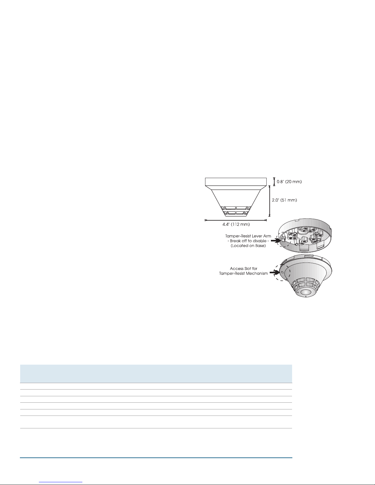
Accessories
All detector mounting bases have wiring terminals that are acces-
sible from the “room-side” after mounting the base to the electrical
box. The bases mount to North American 1-gang boxes and to 3½
inch or 4 inch octagon boxes, 1½ inches (38 mm) deep. They also
mount to European BESA and 1-gang boxes with 60.3 mm fixing
centers. The SIGA-SB4, SIGA-RB4, and SIGA-IB4 mount to North
American 4 inch square electrical boxes in addition to the above
boxes. They include the SIGA-TS4 Trim Skirt which is used to cover
the “mounting ears” on the base. The SIGA-AB4G mounts to a 4”
sqare box only.
Standard Base SIGA-SB, SIGA-SB4 - This is the basic mount-
ing base for EDWARDS Signature Series detectors. The SIGA-LED
Remote LED is supported by the Standard Base.
Relay Base SIGA-RB, SIGA-RB4 - This base includes a relay.
Normally open or closed operation is selected during installation.
The dry contact is rated for one amp (pilot duty) @ 30 Vdc. The
relay’s position is supervised to avoid accidentally jarring it out of
position. The SIGA-RB can be operated as a control relay if pro-
grammed to do so at the control panel (EST3 V. 2 only). The relay
base does not support the SIGA-LED Remote LED.
Audible Base SIGA-AB4G - This base is designed for use where
localized or group alarm signaling is required. When the detector
senses an alarm condition, the audible base emits a local alarm
signal. The optional SIGA-CRR Polarity Reversal Relay can be
used for sounding to other audible bases on the same 24 Vdc
circuit.
Relay and Audible Bases operate as follows:
- at system power-up or reset, the relay is de-energized
- when a detector is installed in the base with the power on, the
relay energizes for four seconds, then de-energizes
- when a detector is removed from a base with the power on,
the relay is de-energized
- when the detector enters the alarm state, the relay is energized.
Isolator Base SIGA-IB, SIGA-IB4 - This base includes a built-in line
fault isolator for use on Class A circuits. A detector must be installed
for it to operate. The isolator base does not support the SIGA-LED
Remote LED.
The isolator operates as follows:
- a short on the line causes all isolators to open within 23 msec.
- at 10 msec intervals, beginning on one side of the Class A
circuit nearest the loop controller, the isolators close to provide
the next isolator down the line with power.
- when the isolator next to the short closes, it reopens within
10 msec.
The process repeats beginning on the other side of the loop controller.
Remote LED SIGA-LED - The remote LED connects to the
SIGA-SB or SIGA-SB4 Standard Base only. It features a North
American size 1-gang plastic faceplate with a white finish and red
alarm LED.
SIGA-TS4 Trim Skirt - Supplied with 4 inch bases, it can also
be ordered separately to use with the other bases to help hide
surface imperfections not covered by the smaller bases.
SIGA-IB
Isolator Base
SIGA-LED
Remote LED
SIGA-RB
Relay Base
SIGA-SB
Standard Base
SIGA-AB4G
Audible Base