Trader Bear BESMOKEY4 User manual

Features
• Photoelectric.
• Suitable for ceiling or wall mounting.
• 240V~ Mains powered, 50Hz, 80mA.
• Approved to AS3786:2014.
• Active Fire listed
• 9V Replaceable battery back-up.
• Single station and / or inter-connectable up to 24 units.
• Low Battery indication.
• 4 terminal.
• Button for Test and Hush control.
• Hinged base/mounting plate for easy battery changing.
• Green a.c. mains LED.
• Red ashing battery indicator.
• Warning Siren 85dBA.
• Active Fire listed.
• Sound pattern: ISO 8201
• Anti-tamper feature.
• Large terminals in easy to install base plate.
Installation and User Manual
BESMOKEY4
Photoelectric Smoke Alarm
with Hinged Base Plate, 4 Terminals
na
ls

Before installing smoke alarm
Remove the product and packaging from the box and ensure the installer
has read through the instructions thoroughly and they are understood
before commencing installation. The installations performance and overall
safety relies on the correct procedures being followed for both connection
and positioning of the units.
Installation planning
• Recommended location of smoke alarms
Standard guidelines should be followed and locations should be
planned for optimum performance when installing the smoke alarms.
The Building Code or Australia and regional Government Legislations
provide direction.
• For optimal performance, alarms should be mounted as close to the
centre of the rooms as practical and on the ceiling for residential
applications (see diagram 2).
• Smoke alarms should be located in the vicinity of sleeping areas, bed
rooms and along the path to the exit as the sleeping quarters are
usually further from building exits.
• Smoke alarms should be mounted near each end of hallways longer
than 9 meters.
• Smoke detectors on ceiling must be installed at least 300mm away
from walls or corners (see diagram 3).
• Where it is necessary to mount smoke alarms on a wall, use the inside
wall of the room and position them between 300 and 500mm from the
ceiling. (See diagram 3).
1

• The alarm should be at least 500mm away from the apex of any angled
ceiling surface and no greater than 1500mm (see diagram 3).
• Alarms should be located in every room where electrical appliances
are used.
• Multi Story
• Alarms should be installed on every oor level.
• Stairwells can act like chimneys as smoke can rise through them, so
additional alarms should be located in these areas (see diagram 1).
Diagram 1
Diagram 2 - Suggest alarm location
Bedroom
Bedroom Bedroom
Living Room
Lounge Room
Kitchen / Dining
2

• Mobile Homes
• For modern mobile homes or caravans with ecient insulation, install
smoke alarms as recommended, refer ‘Recommended location of
smoke alarms’.
• For older and mobile homes and caravans that are not well insulated
on external surfaces compared to current standards, external
temperatures can vary to extreme heat or cold. In these cases the
smoke detector should be mounted on an inside partition between
300 and 500mm from the ceiling surface. This is to overcome the
problem where the temperature conditions on external surfaces may
create a thermal barrier where smoke may not reach the ceiling.
• If unsure of the insulation in the mobile home it is recommended to
install the alarm on an inside wall panel, and for minimum protection
install at least one alarm near bedrooms.
Note: for smoke alarm use in mobile homes it is recommended to test
them before each excursion and at least once a week during use,
particularly if travelling on rough roads.
Diagram 3
3

• Locations to avoid:
• Air-conditioner ducts or appliance outlets that create airow such as
heaters where combustion heat particles rise and spread horizontally.
• Avoid locating the smoke alarms within 1 meter as it can cause
nuisance triggering or smoke particles may be blown away from alarm.
• Avoid installation in kitchen areas as nuisance triggering can occur
from cooking fumes, heat or smoke particles rising.
• Avoid installation in damp areas or extremely humid locations where
relative humidity may reach 90%.
• Avoid installing in areas where there are large temperature variations
such as 5 to 45 degrees as performance may vary in extreme
conditions and battery life may be reduced.
• Avoid installing alarms in areas that are considered“dead air space”
where smoke will unlikely reach the alarm (see diagram 3).
• It is recommended not to locate your alarm in the garage - products of
combustion that are present when you start your vehicle may cause
nuisance triggering.
• Do not locate your alarm less than 500mm from the peak of an "A"
frame type ceiling (see diagram 3).
• Avoid dusty areas or areas where insects may infest the unit as it may
cause nuisance triggering or premature failure.
• Avoid installation in close proximity to other electrical equipment or
uorescent lights as electromagnetic interference may cause nuisance
triggering.
4
Installation
• Only wire BESMOKEY4 alarm to 240V~ 50Hz Sine wave current supply.
• There are four terminals in the supply terminal block, marked A,E,N and S.
It is important that the alarm be wired correctly to ensure correct
operation. Incorrect wiring to the Smoke Alarm will damage the unit and
void the warranty.
• All wiring must be carried out by a licenced electrician and in accordance
with AS/NZS3000 wiring rules with minimum cable size of 1mm2.
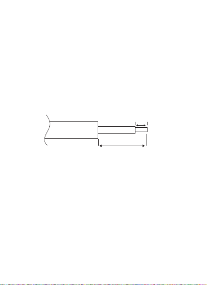
• Ensure the power is switched o, strip Active, Earth and Neutral to the
length shown and insert in correct terminals indicated on the base.
• Tighten the terminal screws fully.
• If interconnected then insert the signal cable into the “S”terminal and
tighten screws (see diagram 4).
• Clip the terminal cover closed to prevent accidental contact with live
parts.
• Fix the smoke alarm to the ceiling or mounting surface using the plugs
and screws provided.
• If the unit is replacing a larger diameter alarm, then the BESMOKEY4SK
skirt can be clipped to the baseplate to cover larger unpainted regions on
the ceiling. (See‘Skirt Instruction’ on back page).
• Clip the hinge tongue into the base plate (if it has been removed) and
install the battery (refer replacing the battery section) then pivot the
alarm closed until the clip clicks on the base plate assembly.
10mm
25mm
5
Strip Length

• Operation and Testing
• Prior to turning on mains to smoke alarm, remove the dust cover, and
ensure the back-up battery is correctly tted and is fully charged over
8.0 Volts, then close the alarm to the base assembly engaging the clip.
• Switch on power and check the green light on alarm cover is
illuminated. It should be lit when mains power is connected and
indicates the unit is correctly connected to the mounting base. The
smoke alarm will be correctly working when the green light is on and
the red light ashes periodically to show the battery is functioning.
• Press the Test/Hush button to conrm the alarm functions correctly.
• If the alarm “chirps” several times press the test button to check the
battery condition is OK.
• If the alarm continues to “chirp”and the battery is in good condition
and tted correctly, remove the alarm and return it to the supplier for
replacement.
Diagram 4
6

• Interconnection of smoke alarms
• Up to 24 units of smoke alarms may be interconnected. Due to “noise”
from electromagnetic interference, more connections should not be
undertaken.
• Do not connect the S interconnect wire to any device, except the S
interconnect terminal of smoke alarm. Otherwise, smoke alarm will be
damaged.
• Do not connect AC power wires to S interconnect terminal. These will
damage smoke alarms.
• A total maximum of 250 meters of cable can be used in
interconnecting smoke alarms.
• All “A,E,N” sub-circuit conductors including the signal conductor “S”
must be a minimum size of 1mm2with 250V rated insulation (see
diagram 5).
• Interconnected Smoke Alarms must be connected to the same
sub-circuit for “A&N”
• Do not use any wire that could later be confused with the normal
house wires for the interconnect wire. For example, green/yellow earth
wire.
• Smoke alarms should be interconnected only within the limits of a
single family dwelling. Do not interconnect alarms between dierent
living units as excessive nuisance triggering may result. Other
occupants may not be aware that smoke alarms are being tested or
that it is a nuisance alarm caused by cooking etc.
• This Smoke Alarm can only interconnect with Trader BESMOKEY4.
Interconnection with other brands or models may cause damage or
result in a shock or re risk and void warranty.
7

AENS AENS AENS
Fuse on
Circuit
Breaker
BESMOKEY4 BESMOKEY4 BESMOKEY4
Connection
to a maximum
of 24 devices
• Hush/Silence Feature
• The Smoke alarm contains a hush/silence feature within the button
labelled HUSH/TEST on the external surface of the alarm.
• If cooking particles or dust have triggered a false alarm the unit can
be temporarily silenced for 8-10 minutes by pressing the HUSH button
for 3 seconds or longer while the particles clear. If smoke continues in
the atmosphere then alarm will recommence sounding.
• Replacing the back-up battery
• Smoke alarms should have their back up batteries replaced regularly
and at least every 12 months or if the low battery signal starts
signalling.
• Use only the following 9 volt batteries for smoke alarm replacement.
Alkaline Type: ENERGIZER 522: DURACELL MN1604, MX1604; Carbon
Zinc Type: Gold Peack 1604E. These batteries can be purchased at your
local retail outlet or supermarket.
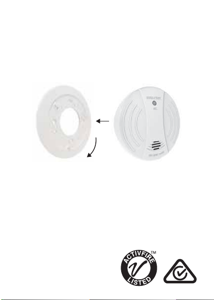
• Open the smoke alarm by pressing the “Push to Open” button (see
diagram 6).
Diagram 5
8

• Replacing the back-up battery (cont.)
• The body of the smoke alarm will pivot down on the hinge to reveal
the battery chamber.
• Remove the 9V d.c. battery from the battery recess.
• Replace the battery with a new equivalent and follow the steps below.
• When installing the new battery ensure the spring loaded battery tag
is correctly pushed down in the chamber by the battery otherwise the
body will not close on the base plate and the alarm will not function
(see diagram 6).
• Close the alarm and latch the clip back in place.
• The alarm should show the green LED lit and the Red LED ashing
periodically.
• Press the TEST function to ensure the alarm is working correctly.
Press the push button and the alarm
will open and swing down on the
hinge plate. The contacts may hold
it closed so the alarm may need some
assistance to open. Access to the battery chamber
Diagram 6
9

Troubleshooting
Function
Normal
Normal
Alarm Mode
Alarm Mode
Hush Mode
Low battery
LED status
Green ON
Red Flashing every 30
seconds.
Red light ashing every
0.5 seconds. Smoke alarm
is activated.
Red light is OFF. Smoke
alarm is activated.
Green Light ON. Red light
every 8 seconds and no
chirp.
Green ON, ashing red
light every 30 seconds.
Recommendation
Green LED indicates a.c. mains
power is present.
Red LED ashes every 30 seconds if
normal. The smoke alarm performs a
self-test every 30 seconds for the
battery and electronics.
Repeats 3 long beeps as per ISO8201
that the alarm has activated and is in
alarm mode.
Smoke alarm is in full alarm mode,
repeat 3 long beeps (ISO8201).
Other interconnected units may
have activated the alarm. Also check
other connected devices.
The “HUSH”feature has the
capability of temporarily
desensitizing the alarm circuit for
approximately 8 minutes.
Smoke alarm chirps every 30
seconds. May indicate low battery
status. Replace battery.
Develop and Escape Plan
• Familiarise everyone with the sound of the smoke alarm and train them
to exit the building when they hear the noise.
• Establish a safe place outside of the home where the occupants can
gather in case of a re such as a driveway near the road.
10

• Have a family meeting to discuss the escape plan so that everyone knows
what to do as people may be located in dierent parts of the dwelling.
• Practice the drill regularly several times a year as it will help familiarise
people for the time there is an emergency and ensure children are
trained what to do.
• It is recommended to make a oor plan and show windows and exits as
well as multiple escape routes in case there is a re in dierent parts of
the dwelling. It is also recommended to plan the escape from second
story windows where a rope or chain ladder may be needed as well as an
easy way to open them if needed to escape.
What to do if alarm sounds
• The most important thing is not to panic.
• Leave immediately by heading towards the exits identied in your escape
plan, don’t waste time collecting valuables or getting dressed. Alert small
children who may need assistance.
• Check the pathway ahead of you for re or smoke and be careful to check
the heat of internal doors before opening as there may be a re on the
other side. If the pathway is blocked by smoke or re, use an alternative
escape path.
• To prevent being overcome by smoke, stay low to the ground, if the air is
lled with smoke, breathe slowly, covering mouth and nose with a cloth.
• Once outside and in the planned safe meeting place, make sure everyone
is present.
• Call the re brigade from your neighbour’s house or mobile, not your
own home phone.
• Don’t enter back into your house until re ocials say it is OK.
11

False Alarms
• Photoelectric type smoke alarms are less prone to false alarm near
kitchen areas than older smoke alarms.
• If the alarm does sound, check for re rst. If a re is discovered, escape
quickly as per the previous section.
• If no re is present, check to see if the reasons are dust, insects, cooking
particles or excessive steam that may have caused the alarm.
Maintenance and repairs
• There are no serviceable parts within BESMOKEY4 alarm that should be
replaced by the user.
• BESMOKEY4 alarm has an expected service life of 10 years under normal
conditions.
• Trader recommends that BESMOKEY4 alarm is replaced 10 years after its
installation date.
• Disconnecting BESMOKEY4 alarm from the mounting base and/or
removing the 9V battery will render this smoke alarm inactive.
Warning: Insulation Test
• Under no circumstances must an insulation resistance test be carried out
on a circuit to which a smoke alarm is tted.
• The test could cause irreparable damage to the internal circuitry of the
smoke alarm and make it inoperative.
• The warranty would be void under such circumstances.
Note: Weekly testing is recommended!
12

Warranty and Liability
If invoice / receipt is presented, GSME will repair or replace the product (at
the option of GSME) due to any manufacturing defect, at the cost of GSME
(excluding any labour costs relating to removal or re-installation of
product, and transport costs) assuming that the product is not altered after
the date of purchase, or if it fails to operate due to improper maintenance.
• To the extent permitted by law, the liability of GSME arising from the sale
or under the terms of this limited warranty shall not in any case exceed
the cost of replacement and subject to this clause. In no case shall GSME
be liable for consequential loss or damages resulting from the failure of
the product or breach of this, or: Any other warranty, express or implied,
loss or damage caused by failure to abide by the instructions supplied in
the leaets.
• To the extent permitted by law, GSME makes no warranty, expressed or
implied, written respect to the consumer replaceable battery if any. A
product with non-serviceable built-in battery is covered under warranty
of the product.
• This warranty is provided in addition to other rights and remedies you
have under law:
Our goods come with guarantees that cannot be excluded under the
Australian Consumer Law. You are entitled to a replacement or refund for a
major failure and compensation for any other reasonably foreseeable loss
or damage. You are also entitled to have the goods repaired or replaced if
the goods fail to be of acceptable quality and the failure does not amount
to a major failure. What constitutes a major failure is set out in the
Australian Consumer Law.
13

• To make a claim under warranty, take the product (with a proof of
purchase) to the store where you purchased the product or contact GSME
expense claim in writing.
Please retain this warranty section and complete the details below. When
you claim Warranty for the product please present this section together
with the faulty product.
Model:____________________ Serial Number: _______________________
Date Of Purchase/ Installation: _________________ Invoice No:
___________
Installed By:
____________________________________________________________
_________________________________________________________
Owner's Details:
_________________________________________________________
This smoke alarm has been tested and complies to AS3786:2014
14
GSM Electrical (Australia) Pty Ltd
Level 2 142-144 Fullarton Road
Rose Park SA 5067
www.gsme.com.au
Phone: 1300 301 838
Fax: 1300 301 778
Skirt Instruction
When replacing larger diameter smoke alarms with the BESMOKEY4, the
BESMOKEY4SK skirt can be clipped onto the base plate before wiring or
installation to the ceiling, to provide a clean solution to cover any dissimilar
paint marks.
The tabs can be pushed in place and rotated to lock the alarm in place with
the skirt.
Table of contents
Other Trader Smoke Alarm manuals


Popular Smoke Alarm manuals by other brands


LST
LST GM-55000-137 Specification sheet

Red Smoke Alarms
Red Smoke Alarms R9 installation instructions

Elkron
Elkron SD610 Installation, programming and functions manual

Bosch
Bosch FMM-100 Series manual

Nexa
Nexa ZSD-109 user manual

Arrowhead Alarm Products
Arrowhead Alarm Products HM-SMOKE quick start guide