30311161 Issue 1.01
Test zone
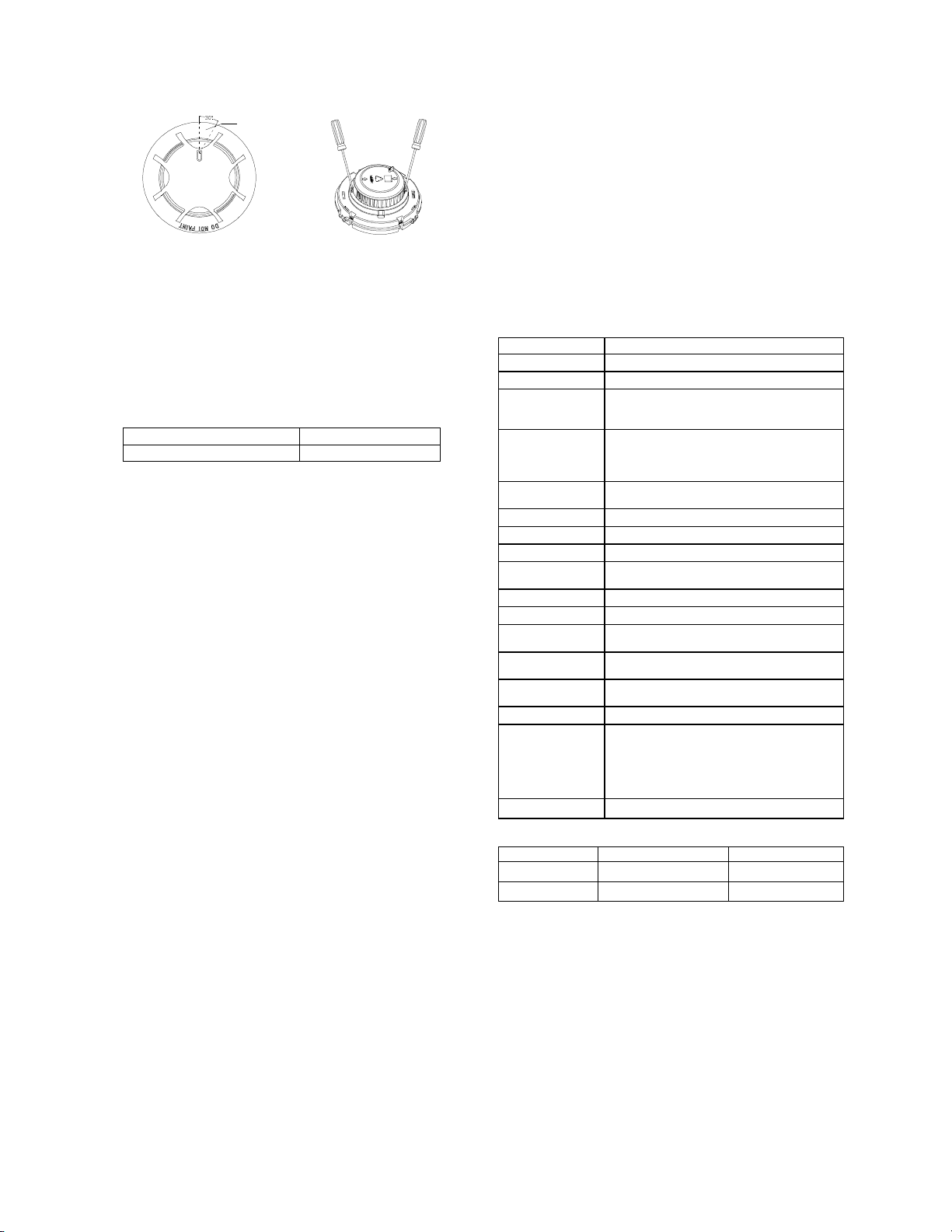
Fig. 5 Fig. 6
1) Reed Switch Testing
Magnet test zone is shown in Fig.5. Put the magnet of commission
tool close to the zone of the detector and hold on for a few seconds
until the detector generates alarm.
1) Smoke test
The Trutest model 300 Aerosol Smoke Detector Tester can be used
for smoke entry testing. Set the generator to represent 4%/ft to 5%/ft
obscuration as described in the Trutest manual. Using the bowl
shaped applicator, apply aerosol until the panel alarms.
Additionally, canned aerosol simulated smoke (canned smoke agent)
may be used for smoke entry testing of the smoke detector.
Recommended aerosol smoke products are:
Manufacturer Model
Trutest AERO400
When used properly, the canned smoke agent will cause the smoke
detector to go into alarm. Refer to the manufacturer’s published
instructions for proper use of the canned smoke agent.
2) After testing, cut off the power above 10 seconds and reset the
detector and then notify the proper authorities that the system is
back in operation.
Warning: Canned aerosol simulated smoke (canned smoke agent)
formulas will vary by manufacturer. Misuse or overuse of these
products may have long term adverse effects on the smoke detector.
Consult the canned smoke agent manufacturer’s published
instructions for any further warnings or caution statements.
When testing is complete, restore the system to normal operation
and notify the proper authorities that the system is back in operation.
Maintenance
1. The detector must be cleaned once a year to ensure normal
operation of the system.
2. Before cleaning, notify the proper authorities that the system is
undergoing maintenance and will temporarily be out of service.
Disable the zone or system undergoing maintenance to avoid
unwanted alarms.
Chamber Clearing Steps:
a) Open the top cover of detector, and draw out the sensing
chamber by slightly lifting its two sides using a straight
screwdriver, as shown in Fig. 6.
b) Use a vacuum cleaner or cleaned, compressed air to
remove dust and debris from the insect guard and the sensing
chamber. The sensing chamber can also be cleaned by clear
water and brush. Put the sensing chamber in clean water to
brush the dust inside and take out to dry it.
c) Install the sensing chamber and the top cover back.
Cautions
1. Dust covers can’t be removed until the project is put into use
formally. Take well care of dust covers for future use.
2. Dust covers effectively but not absolutely prevent dust particles
from going into detectors. So, we recommend that detectors
should be removed prior to construction, decoration, or other
activities producing dust. The proper authority should be informed
of detectors removing.
3. Be careful not to damage the detector in maintenance.
The smoke detector may not sense fire that where smoke cannot
reach it, such as in chimneys, in walls, on roofs, or on the other
side of closed doors.
4. The detector cannot monitor the place beyond protection area.
5. The detector may not warn you about fires caused by
insufficient safety measures, violent explosions, leaking gas,
improper storage of flammable materials like diluents and other
safety hazards, arson or children playing with fire.
6. The alarm of a smoke detector used in high velocity
environment will be delayed due to dilution of smoke by frequent
and fast airflow.
7. Smoke detectors have their own service life. In order to keep
the detector working in good condition, please maintain them
according to recommendations from manufacturers and relative
state standards.
8. The detectors must be tested regularly, at least once a year.
9. Smoke detectors are not to be used with detector guards
unless the combination has been evaluated and found suitable for
that purpose.
Specification
Operating Voltage 16VDC~28VDC
Standby Current ≤60μA
Alarm Current ≤55mA
Fire LED Red, periodically flash once in polling,
Periodically flash twice in fault or sensing
chamber dirty; illuminate in alarming.
Alarm Output Polarized output. Cycle 0.25S, duty ratio 1/2,
Voltage range 13V~24V(built in 10k resistor in
series, maximum output current is 2.0mA);
Max. ripple
voltage 2V(peak to peak value)
Alarm reset Instant power down (10s Min, 1.0VDC Max
Wiring Two-wire, polarity sensitive.
Sensitivity Range 1.23%~3.20% per ft
Environment
Temperature 32℉(0℃)~100℉(+37.8℃)
Relative Humidity ≤95%, non condensing
Material and color ABS, white (RAL 9016)
Ingress Protection
Rating IP2X
Dimension Diameter:100mm Height: 44.5mm (without
base)
Mounting Hole
Spacing 45mm-75mm
Weight About 110g
Compatibility EST3/3x IDC (detector capacity:19)
SIGA-UM/MAB(detector capacity:10)
RZI16-2 (detector capacity:25)
Fireshield Plus(detector capacity:25)
Listing UL268
Accessories and Tools
Model Name Remark
EDB-M01 Base Supplied separately
T-MT Commission tool Supplied separately


