EEPD BoxPC-NUCV User manual
BoxPC-NUCV|NUCR – Revision 3 - Device Reference Manual – P –
Copyright © 2019|2020 by E.E.P.D. GmbH. All rights reserved. | Rev. 3.0
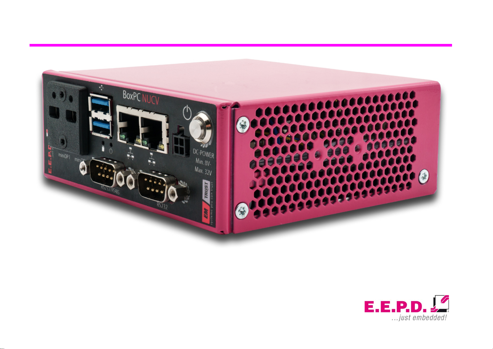
Picture shows BoxPC-NUCV with custom color option and various other options

BoxPC-NUCV|NUCR
Device Reference Manual – P – Revision 3
E.E.P.D. GmbH | Gewerbering 3 | 85258 Weichs
Copyright © 2019|2020 by E.E.P.D. GmbH. All right reserved. |
Rev.3.0
1
Manufacturer
E.E.P.D. Electronic Equipment Produktion & Distribution GmbH
Gewerbering 3
85258 Weichs
Phone.: +49 8136 2282 – 0
Fax.: +49 8136 2282 – 109
Web: https://www.eepd.de
03/2020 Version 3.0
General Notes
This user manual is for your information only.
The information contained herein has been checked carefully and is
believed to be reliable. However, E.E.P.D. GmbH gives no guarantee or
warranty concerning the accuracy of spoken information and shall not be
responsible for any loss or damage of any nature resulting from the usage of
or from reliance upon it.
We are thankful for all suggestions or improvements at any time.
E.E.P.D. GmbH reserves the right to make changes in the products or
specifications, or both, at any time without notice.
Copyright Notice
Copyright©2019|2020 E.E.P.D. GmbH. ALL RIGHTS RESERVED!
E.E.P.D. GmbH copyrights this document. You may not reproduce, transmit,
transcribe, store in a retrieval system, or translate into any language or
computer language, in any form or by any means, or otherwise, any part of
this publication without the express written permission of E.E.P.D. GmbH.
Trademark Acknowledgement
E.E.P.D.® and EMTRUST® are registered trademarks of E.E.P.D. GmbH.
All rights reserved. All other mentioned trademarks are registered
trademarks of their owners.

BoxPC-NUCV|NUCR
Device Reference Manual – P – Revision 3
E.E.P.D. GmbH | Gewerbering 3 | 85258 Weichs
Copyright © 2019|2020 by E.E.P.D. GmbH. All right reserved. |
Rev.3.0
2
Disclaimer
This document is provided for the general information of the customer. It
describes the general functionality of the system and is not considered as
assured characteristics. The written declarations in this specification are not
constituent part of any contract.
E.E.P.D. GmbH reserves the right to modify the information contained in this
manual as necessary and the customer should ensure that he has the most
recent revision of this document.
E.E.P.D. GmbH makes no warranty for the use of its products and bears no
responsibility for any errors, which may appear in this document. The
customer should be on notice that the field of personal computers is the
subject of many patents held by different parties. Customers must ensure
that they take appropriate action so that their use of the products does not
infringe upon any patents. It is the policy of E.E.P.D. GmbH to respect the
valid patent rights of third parties and not to infringe upon or assist others to
infringe upon such rights.
E.E.P.D. GmbH assumes no responsibility for circuits, descriptions and
tables within this document as far as patents or other rights of third parties
are concerned.
Life Support Applications
E.E.P.D. GmbH products are not intended for being used as critical
components in life support appliances, devices or systems in which the
failing of an E.E.P.D. GmbH product could be expected to result in personal
injury.
FCC and CE Disclaimer
E.E.P.D. GmbH gives no warranty at all that their products will meet the
FCC and CE standards when used in combination with other third party
products or when used in any other way than specified.
Limited Warranty
This product will be free from defects in workmanship and material under
normal and proper use for the period of time defined in our General Terms of
Business, effective the date of the original shipment from E.E.P.D. GmbH.
In the event of a warranty claim for defects, which appear within the
warranty period, customer shall deliver the product along with proof of
purchase to the original place of purchase, shipping prepaid. Repair,
replacement or refund of the purchase price of the defective product will be
at the sole option of the manufacturer. All transportation risks and costs in
connection with warranty service are the responsibility of the customer.
THIS WARRANTY IS IN LIEU OF ALL OTHER WARRANTIES, EXPRESS
OR IMPLIED, INCLUDING WITHOUT LIMITATION, IMPLIED
WARRANTIES OF MERCHANTABILITY AND FITNESS FOR A
PARTICULAR PURPOSE, TO ANY CUSTOMER, CONSUMER, END USER,
PURCHASER, OR OTHERWISE. IN NO EVENT SHALL MANUFACTURER
BE LIABLE FOR LOSS OF PROFITS, INDIRECT, SPECIAL, INCIDENTAL,
OR CONSEQUENTIAL DAMAGES ARISING OUT OF ANY BREACH OF
CONTRACT OR WARRANTY, NEGLIGENCE, STRICT LIABILITY OR
OTHERWISE.
The remedies for defects in this product are limited to those set forth above.
If this limitation of remedies is held by any court to be void or unenforceable,
or if no warranty is made, manufacturers liability shall in no event exceed the
purchase price of the product giving rise to the claim, regardless of whether

BoxPC-NUCV|NUCR
Device Reference Manual – P – Revision 3
E.E.P.D. GmbH | Gewerbering 3 | 85258 Weichs
Copyright © 2019|2020 by E.E.P.D. GmbH. All right reserved. |
Rev.3.0
3
such claim is brought in breach of contract or warranty, negligence, strict
liability or otherwise.
Reshipment
If you return the BoxPC system to E.E.P.D. GmbH please remove all
connections and peripheral equipment.
Protect the unit with a suitable packaging, preferably use the original
packaging.
Packaging
The BoxPC system is in a protective package to avoid damage during
transport.
This protective package should be recycled in an environmentally friendly
way after use.
Disposal of Device
At the end of the lifetime please dispose and/or recycle the
components of the device accordingly.
Customer Support
Please contact:
https://www.eepd.de/support/
Technical Support
For technical information about hardware and software please contact:

BoxPC-NUCV|NUCR
Device Reference Manual – P – Revision 3
E.E.P.D. GmbH | Gewerbering 3 | 85258 Weichs
Copyright © 2019|2020 by E.E.P.D. GmbH. All right reserved. |
Rev.3.0
4
Table of Contents
General Notes ...............................................................................................1
Symbols.........................................................................................................5
Safety Instructions .......................................................................................6
Safety of People .............................................................................................6
Device Safety..................................................................................................6
Cooling System...............................................................................................6
System Information......................................................................................7
Required Tools ...............................................................................................7
External Notice ...............................................................................................7
Software..........................................................................................................7
Options ...........................................................................................................7
Accessories ....................................................................................................8
System Features and Intended Use...............................................................8
Scope of Delivery..........................................................................................9
Type Label......................................................................................................9
System Mounting..........................................................................................9
System Dimensions......................................................................................10
DIN Rail Mounting (optional) ........................................................................12
Technical Data ............................................................................................14
Interfaces.....................................................................................................15
Connection Overview....................................................................................15
MicroSIM Card..............................................................................................16
MicroSD Card ...............................................................................................16
Power Button | Power and HDD/SSD LED...................................................17
Pin Assignment...........................................................................................18
MiniDisplay Ports..........................................................................................18
Dual-USB 3.0................................................................................................18
Gigabit Ethernet Dual-Port............................................................................19
Power Connector (DC) .................................................................................19
RS232 (optional)...........................................................................................20
RS232 / RS485 (UART / optional)................................................................20
Rear USB 3.0 Port........................................................................................21
MicroSD Slot.................................................................................................21
Commissioning...........................................................................................22
Switching on the device / Operation.............................................................22
Revision History..........................................................................................23
Index of Figures..........................................................................................24
Index of Tables............................................................................................24
List of Abbreviations..................................................................................25
BoxPC-NUCV|NUCR
Device Reference Manual – P – Revision 3
E.E.P.D. GmbH | Gewerbering 3 | 85258 Weichs
Copyright © 2019|2020 by E.E.P.D. GmbH. All right reserved. |
Rev.3.0
5
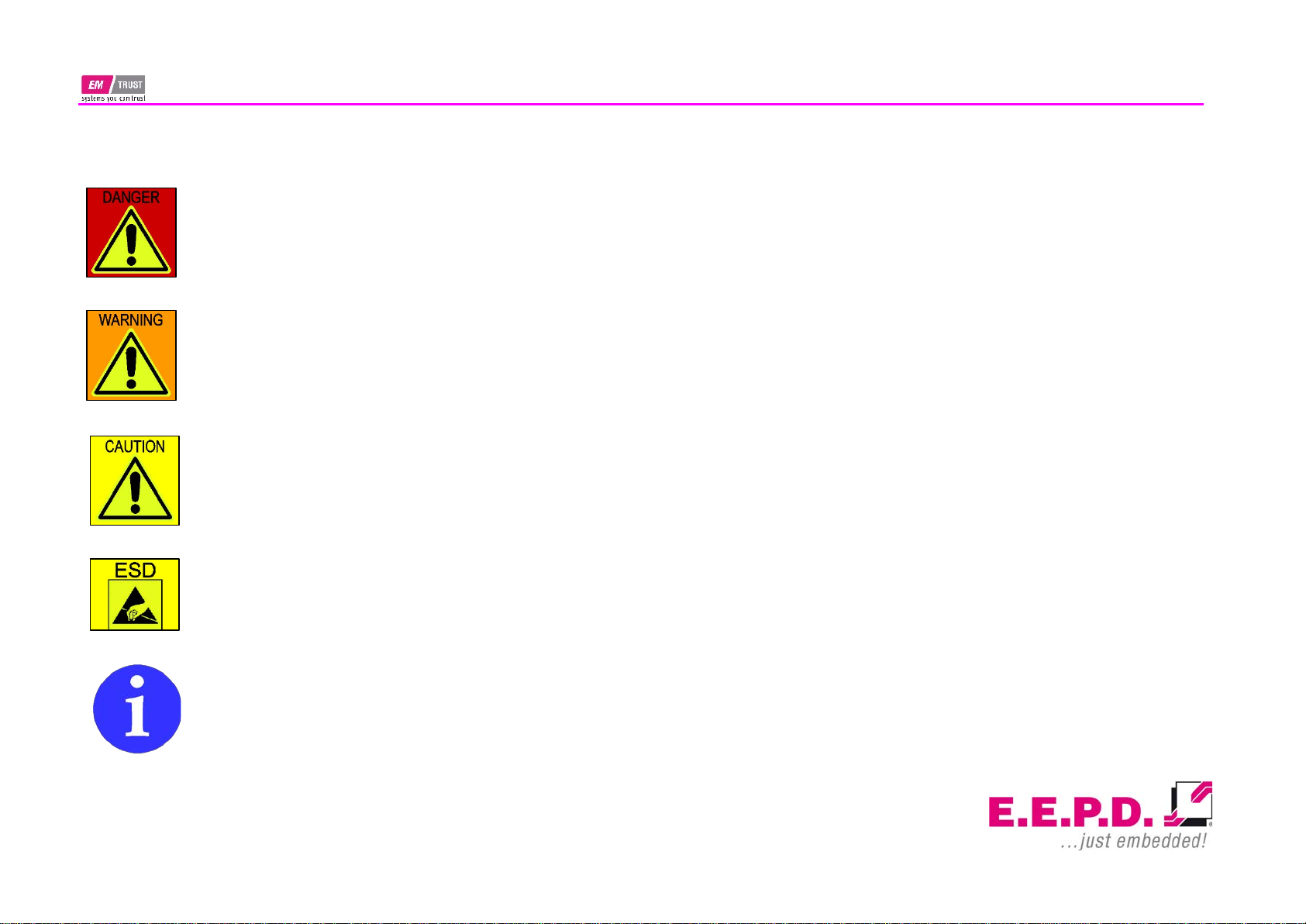
Symbols
The red danger sign warns you if incorrect operation puts
your life or health at great risk. Both the components and the
peripherals could be destroyed.
The orange warning sign warns you that an incorrect or
missing operation could seriously endanger your health or
destroy the used components.
The yellow caution sign indicates that an incorrect or missing
action could damage the components.
The yellow ESD symbol indicates that electrostatic sensitive
components could be destroyed. Unpack shielded
components only with ESD protection such as an ESD
wristband or on an ESD protected area.
The information sign gives you further information and
advice for optimal use of this product.
For example, it draws your attention to necessary or optional
accessories.

BoxPC-NUCV|NUCR
Device Reference Manual – P – Revision 3
E.E.P.D. GmbH | Gewerbering 3 | 85258 Weichs
Copyright © 2019|2020 by E.E.P.D. GmbH. All right reserved. |
Rev.3.0
6
Safety Instructions
Safety of People
The product generates considerable heat. The housing
transports this heat to the environment and thus becomes
hot. Take care if you touch the housing as this may cause
burns!
Please follow all safety instructions at the installation site.
Make sure that no or only necessary cables are connected to
the BoxPC during installation.
If access to the BoxPC interfaces is not available after
installation, all necessary connections must be made before.
Device Safety
The BoxPC operates exclusively within the specified DC
voltage range. Repair work should only be made by an
authorized and certified specialty retailer or by the
manufacturer's customer service. Do not open the device to
avoid damage.
Modifications that have not been approved by the manufacturer void the
warranty. Dust, dirt, moisture, and extreme temperatures may significantly
impair proper operation.
Cooling System
The BoxPC consists of a compact, robust metal housing
with ventilation holes. It is equipped with an automated fan.
To ensure sufficient heat dissipation, never cover the
ventilation holes of the case. Do not place any objects onto
the device.

BoxPC-NUCV|NUCR
Device Reference Manual – P – Revision 3
E.E.P.D. GmbH | Gewerbering 3 | 85258 Weichs
Copyright © 2019|2020 by E.E.P.D. GmbH. All right reserved. |
Rev.3.0
7
System Information
Required Tools
For the installation of the BoxPC system the following standard tools are
recommended:
•Rail mounting: Torx screwdriver T10
•Cable connection: Slot screwdriver
Other required tools are depending on the installation place and method.
External Notice
All external documentation to install the BoxPC system should be obeyed.
Software
Supported operating systems are Microsoft® Windows® 10, Microsoft®
Windows® 10 IoT Enterprise und Linux Ubuntu 18.04 LTS.
Options
Options
Description
Memory*
V1000 processors: Max. 32 GB dual-
channel DDR4 SODIMM up to 3200 MT/s
R1000 processors: Max. 32GB dual-
channel DDR4 SODIMM up to 2400 MT/s
R1000 R1102G processor: Max. 16GB
single-channel DDR4 SODIMM up to 2400
MT/s
SSD*
64 GB – 512 GB
LTE/modem module*#
M.2 LTE card with three SMA connectors
WLAN/BT module kit*#
M.2 WLAN/BT card with 2 SMA-connectors
Operating System*
Windows® 10, Windows® 10 IoT
Enterprise, Linux Ubuntu 18.04 LTS
RS232 cable*
9-pin D-SUB plug
RS485 cable*
9-pin D-SUB plug
Power switch*
Power switch with LED
Sound*
Audio connector 3.5 mm MIC IN /
headphone OUT / CTIA-Standard
*factory assembled on request
#
ODM option
Tab. 1: Options

BoxPC-NUCV|NUCR
Device Reference Manual – P – Revision 3
E.E.P.D. GmbH | Gewerbering 3 | 85258 Weichs
Copyright © 2019|2020 by E.E.P.D. GmbH. All right reserved. |
Rev.3.0
8
Accessories
For accessories please contact our sales department.
Accessories
Description
4-pin power cable
Power cable with open ends
Power supply (90 W / 24 V)
Power supply incl. cable with EU plug
Display cable
Cable MiniDP to HDMI, 2 m, with interlock
WLAN/BT antenna
SMA antenna
LTE/GPS antenna
SMA antenna with or without cable
DIN rail clip
DIN rail clip with screws for „TS35“ hat-rails
Tab. 2: Accessories
System Features and Intended Use
The BoxPC is the perfect industrial grade communicator for secure and
reliable IoT communication. Many interfaces provide a wide range of
applications. The simultaneous use of 4G(ODM only) and WLAN(ODM only)
allows extended router applications.
The BoxPC is intended for indoor use only.

BoxPC-NUCV|NUCR
Device Reference Manual – P – Revision 3
E.E.P.D. GmbH | Gewerbering 3 | 85258 Weichs
Copyright © 2019|2020 by E.E.P.D. GmbH. All right reserved. |
Rev.3.0
9
Scope of Delivery
Before you begin installation, please check that your shipment is complete
and contains the items listed on the delivery note.
Type Label
Fig. 1: Type label
1– Manufacturer
2– Product name
3– Serial number with barcode
4– Technical data
5– Certification information
System Mounting
For use as a desktop computer, apply the self-adhesive rubber feet to the
bottom of the housing.
Before attaching the rubber feet, please clean / degrease the
bonding areas with a suitable solvent, e.g. alcohol.
Fig. 2: BoxPC-NUCV with rubber feet
Fig. 3: Front View with rubber feet
2
1
3
4
5

BoxPC-NUCV|NUCR
Device Reference Manual – P – Revision 3
E.E.P.D. GmbH | Gewerbering 3 | 85258 Weichs
Copyright © 2019|2020 by E.E.P.D. GmbH. All right reserved. |
Rev.3.0
10
System Dimensions
Fig. 4: Dimensions frontside, all values approx. in mm
Fig. 5: Dimensions backside, all values approx.. in mm
Fig. 6: Dimensions left side, all values approx. in mm
Fig. 7: Dimensions right side, all values approx. in mm
BoxPC-NUCV|NUCR
Device Reference Manual – P – Revision 3
E.E.P.D. GmbH | Gewerbering 3 | 85258 Weichs
Copyright © 2019|2020 by E.E.P.D. GmbH. All right reserved. |
Rev.3.0
11
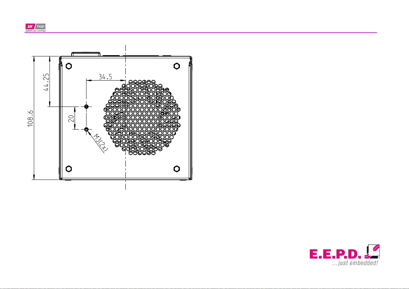
Fig. 8: Dimensions bottom side, all values approx. in mm

BoxPC-NUCV|NUCR
Device Reference Manual – P – Revision 3
E.E.P.D. GmbH | Gewerbering 3 | 85258 Weichs
Copyright © 2019|2020 by E.E.P.D. GmbH. All right reserved. |
Rev.3.0
12
DIN Rail Mounting (optional)
The BoxPC is also designed for DIN rail mounting. There are drilled holes
for mounting the optional DIN rail holder in various positions (Fig.9).
Symbolic view for both sides.
Fig. 9: DIN rail holder positions
Please follow the instructions below:
•Mount the top-hat rail holder with two screws M3x6mm at the
intended fastening points (see Fig.9+10). The top-hat rail holder is
suitable for “TS35” DIN rails.
•Place the system on the DIN rail. Swivel it inwards until it snaps
securely into place.
•To detach the system, push it from bottom to top. Swivel it outwards
and remove it.
Fig. 10: DIN rail holder mounting
BoxPC-NUCV|NUCR
Device Reference Manual – P – Revision 3
E.E.P.D. GmbH | Gewerbering 3 | 85258 Weichs
Copyright © 2019|2020 by E.E.P.D. GmbH. All right reserved. |
Rev.3.0
13
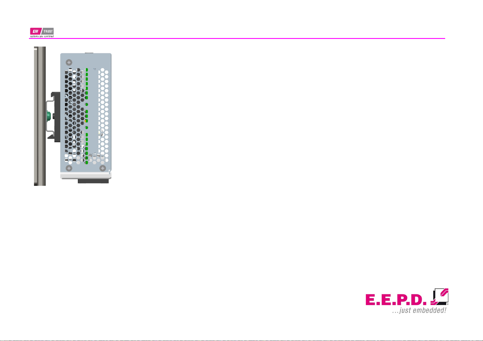
Fig. 11: Side View DIN rail mounted system

BoxPC-NUCV|NUCR
Device Reference Manual – P – Revision 3
E.E.P.D. GmbH | Gewerbering 3 | 85258 Weichs
Copyright © 2019|2020 by E.E.P.D. GmbH. All right reserved. |
Rev.3.0
14
Technical Data
•AMD V1000 processor series:
oV1202B / 2C / 4T / 2.3 GHz – 3.2 GHz / 12 – 25 W (ODM
option only)
oV1605B / 4C / 8T / 2.0 GHz – 3.6 GHz / 12 – 25 W
oV1756B / 4C / 8T / 3.25 GHz – 3.6 GHz / 35 – 54 W
(max.35W TDP supported by design | ODM option only
oV1807B / 4C / 8T / 3.35 GHz – 3.8 GHz / 35 – 54 W
(max.35W TDP supported by design)
oV1404B / 4C / 8T / 2.8 GHz – 3.6 GHz / 12 – 25 W,
extended Temp -40 - +85°C
•AMD R1000 processor series
oR1102G / 2C / 2T / 1.2 GHz – 2.6 GHz / 6 W
oR1305G / 2C / 4T / 1.5 GHz – 2.8 GHz / 8 - 10 W
oR1505G / 2C / 4T / 2.4 GHz – 3.3 GHz / 12 – 25 W
oR1606G / 2C / 4T / 2.6 GHz – 3.5 GHz / 12 – 25 W
•Memory V1000 processor series: max. 32 GB dual-channel DDR4
•Memory R1000 processor series: max. 32 GB dual-channel DDR4
•Memory R1102G processor: max. 16GB single-channel
•Ethernet: 2 Intel® i210 with IEEE1588
•LTE/4G (ODM option): 300 Mbps max. / EMEA, APAC /
Diversity / GNSS
•WiFi/BT (ODM option): 802.11 AC with diversity / Bluetooth version 5
•SSD (optional): M.2 SATA or NVME / 64 – 512 GB
•SD card: with MicroSD slot, not bootable
•USB ports: 3 USB 3.1 Gen1
•Serial ports (optional): 1 RS-232 / 1 RS-232/485(FDX only)
•2 Mini-DP++ connectors up to 4096 x 2160 @ 60 Hz
•Sound (optional): 3.5 mm MIC In / headphone Out
•Controlled FAN (PWM + Tacho), hardware monitoring and
watchdog
•Power and Status LED
•Power supply: Min. 8 V / Max. 32 V (DC)
Suitable for direct connection to vehicle board networks
•(12 V / 24 V)
•Operating temperature: 0
°C to +60
°C ambient commercial grade
oOperating temperature of BoxPC-NUCH with V1404B
processor: -40
°C to +85
°C ambient industrial grade
•Storage temperature: -40
°C to +85
°C
•Relative humidity: 95
% @ 40
°C, non-condensing
•Housing: sturdy metal case
•Mounting: stand alone or top-hat rail
•Dimensions approx: 117 x 44 x 113 mm
•Weight: approx. 700g
•Conformity: CE, ROHS, REACH

BoxPC-NUCV|NUCR
Device Reference Manual – P – Revision 3
E.E.P.D. GmbH | Gewerbering 3 | 85258 Weichs
Copyright © 2019|2020 by E.E.P.D. GmbH. All right reserved. |
Rev.3.0
15
Interfaces
Connection Overview
The BoxPC is equipped with the following standard interfaces:
1– 2x Mini-DP++ connector
2– Dual-USB 3.0 port, type A
3– 2x Ethernet 10/100/1000 Mbit/s (RJ45)
4– Power supply
5– Power button
6– MicroSD card slot
7– USB 3.0 port, type A
Depending on the version, additional interfaces are available. The following
table shows the standard systems.
System ordering
code
Description
BPCNVA
V1202C / 2C / 4T / 2.3 GHz – 3.2 GHz / 12 – 25 W
BPCNVB
V1605C / 4C / 8T / 2.0 GHz – 3.6 GHz / 12 – 25 W|#
BPCNVC
V1756C / 4C / 8T / 3.25 GHz – 3.6 GHz / 35 – 54
W*|
#
BPCNVD
V1807C / 4C / 8T / 3.35 GHz – 3.8 GHz / 35 – 54 W*
BPCNVE
V1404B / 4C / 8T / 2.8 GHz – 3.6 GHz / 12 – 25 W
BPCNRA
R1505G / 2C / 4T / 2.4 GHz – 3.3 GHz / 12 – 25 W
BPCNRB
R1606G / 2C / 4T / 2.6 GHz – 3.5 GHz / 12 – 25 W
BPCNRC
R1102G / 2C / 2T / 1.2 GHz – 2.6 GHz / 6 W
BPCNRD
R1305G / 2C / 4T / 1.5 GHz – 2.8 GHz / 8 - 10 W
*supports only max. 35W TDP settings | #ODM only
Tab. 3: Standard Systems
Front View
Fig. 12: BoxPC-NUCV Front View
Rear View
Fig. 13: BoxPC-NUCV Rear View
4
3
2
1
5
7
6

BoxPC-NUCV|NUCR
Device Reference Manual – P – Revision 3
E.E.P.D. GmbH | Gewerbering 3 | 85258 Weichs
Copyright © 2019|2020 by E.E.P.D. GmbH. All right reserved. |
Rev.3.0
16
MicroSIM Card
In order to insert the MicroSIM card, open the housing.
Remove the screws on the left, right and rear side (Fig.14). Then you can
take off the cover plate.
Fig. 14: Housing Screws
Fig. 15: Open Housing | MicroSIM Card Slot
To lock the card, fully insert it into the slot (Fig.15). Make sure the golden
contacts are downwards.
To remove the card, first push it inwards.
MicroSD Card
It is not necessary to open the case to insert the microSD card. The required
slot is located at the rear side of the system (Fig.16).
To lock the card, slide it completely into the slot until you hear a click. To
remove it, first push the card inwards.
Fig. 16: MicroSD Card Slot
MicroSIM Card Slot
MicroSD Card Slot

BoxPC-NUCV|NUCR
Device Reference Manual – P – Revision 3
E.E.P.D. GmbH | Gewerbering 3 | 85258 Weichs
Copyright © 2019|2020 by E.E.P.D. GmbH. All right reserved. |
Rev.3.0
17
Power Button | Power and HDD/SSD LED
Press the power button (Fig.17) once to switch on the computer.
Hold the power button (>4 Sec.) to turn the system off.
Fig. 17: Power Buttons
Optional Power Button
HDD/SSD-LED
Power-LED
Power button accessible with a paperclip

BoxPC-NUCV|NUCR
Device Reference Manual – P – Revision 3
E.E.P.D. GmbH | Gewerbering 3 | 85258 Weichs
Copyright © 2019|2020 by E.E.P.D. GmbH. All right reserved. |
Rev.3.0
18
Pin Assignment
MiniDisplay Ports
Standard pin assignment
Fig. 18: MiniDisplay port detail
Fig. 19: MiniDisplay port schematic
Important Note:
There are two kinds of DisplayPort cables available:
Cables for direct connection to a MiniDisplay Port monitor
with Pin 20 on both ends of the cable NOT connected.
Cables for use with dongles (e.
g. MiniDisplay Port to
Display Port, MiniDisplay Port to HDMI) with Pin 20 on both
ends of the cable connected.
Possible effects if wrong cable is used:
System might not start up properly.
Dongle doesn’t work properly (e.g. black display).
Dual-USB 3.0
Standard pin assignment
Fig. 20: Dual-USB 3.0 detail
Fig. 21: Dual-USB 3.0 schematic

BoxPC-NUCV|NUCR
Device Reference Manual – P – Revision 3
E.E.P.D. GmbH | Gewerbering 3 | 85258 Weichs
Copyright © 2019|2020 by E.E.P.D. GmbH. All right reserved. |
Rev.3.0
19
Gigabit Ethernet Dual-Port
Standard pin assignment
Fig. 22: Dual-Ethernet detail
Fig. 23: Dual-Ethernet schematic
Yellow LED
Speed-LED is on during 1 Gbit transmission and switched off during 10/100
Mbit transmission.
Green LED
Link-/Activity-LED is permanently on to indicate an active connection on the
Ethernet port. LED flashes during communication with the Ethernet network.
Power Connector (DC)
Fig. 24: Power connector detail
Fig. 25: Power connector schematic
Counterpart - plug:
Nexus Series 2300, 3.00 mm Micro MF Housing with Lock
Ordering Number: 2300P04XXX
Pin
Signal
Description
1
GND_IN
Ground
2
GND_IN
Ground
3
PVIN
DC+ (min. 8 V to max. 32 V)
4
KL_15
Ignition
Tab. 4: Pin assignment power connector
This manual suits for next models
1
Table of contents
Popular Industrial PC manuals by other brands


Hitachi
Hitachi HF-W100E instruction manual

Advantech
Advantech EIS-S232 user manual

Advantech
Advantech Watchdog Timer UNO-2170 user manual

DT Research
DT Research 139CS Operation manual

GIGAIPC
GIGAIPC QBiX-JMB-CMLA47EH-A1 Startup manual

Moxa Technologies
Moxa Technologies MC-7400 Series Quick installation guide