EF EFH 9731 HM VGB (PUB) User manual

1
LICITY
BUILT-IN GAS HOB
BATTERY IGNITION
Model:
EFH 9731 HM VGB (PUB)
EFH 9731 HM VGB (LPG)
EFH 9721 HM VGB (PUB)
EFH 9721 HM VGB (LPG)
EFH 7622 HM VGB (PUB)
EFH 7622 HM VGB (LPG)
EFH 7632 HM VGB (PUB)
EFH 7632 HM VGB (LPG)
THE BEAUTY OF SIMPLICITY
USER MANUAL

2
Dear Customer,
Thank you for having purchased and given your preference to our product. This manual provides a means to
make full use of the features of this product. The safety precautions and recommendations are also featured in
this manual. We recommend that you read this manual for best performance and to extend the life of your
appliance.
Please preserve this manual for future use, in the event that doubts arise relating to the operation.
Close-up View
A. Double Ring Wok Burner 4.5Kw
B. Semirapid 2Kw
D. Control Knobs for Gas Burner
E. Ignitor for Gas Burners
F. Safety Device - Activates if the flame accidentally goes
off (spills, drafts, etc.), interrupting the delivery of gas
to the burner.
3
IMPORTANT WARNING ON THE GLASS

4
Technical Specifications
The appliance can be used for built in or free standing. It comes with two or three burners with glass panel.
Each burner, which is operated by FSD type gas valve, is controlled by metal control knobs positioned at
the front of the panel. Each burner incorporates with thermocouple (Flame Failure Device).
The appliance comes with a battery supply of 1.5V for ignition system. The detail of the models is listed
below:
Model number Burner Variants
Wok
burner Auxiliary
burner Variants Total Dimensions
FH 7622 HM VGB (LPG) 2 0 9kW(655g/h) (760 X 450)mm
EFH 7632 HM VGB (LPG) 2 1 11kW(800g/h) (760 X 450)mm
EFH 9721 HM VGB (LPG) 2 0 9kW(655g/h) (860 X 500)mm
EFH 9731 HM VGB (LPG) 2 1 11kW(800g/h) (860 X 500)mm
Note: Wok burner = Rated at 4.5kW. Auxiliary burner = Rated at 2.0kW.
Model number Burner Variants
Wok
burner Auxiliary
burner Variants Total Dimensions
FH 7622 HM VGB (PUB) 2 0 9kW (760 X 450)mm
EFH 7632 HM VGB (PUB) 2 1 11.3kW (760 X 450)mm
EFH 9721 HM VGB (PUB) 2 0 9kW (860 X 500)mm
EFH 9731 HM VGB (PUB) 2 1 11.3kW (860 X 500)mm
Note: Wok burner = Rated at 4.5kW. Auxiliary burner = Rated at 2.3kW.
Burner Injector size
(mm) Injector marking Full rate
kW
For LPG
Wok Inner ring 0.4 40 4.5
Outer ring 0.95 95
Auxiliary 0.65 65 2
For TG (G110)
Wok Inner ring 1.3 130 4.5
Outer ring 3.2 320
Auxiliary 2.2 220 2.3

5
Safety Guidelines
•
Please do not allow young children to play with the plastic film and packaging as this may result in
suffocation.
•
After having unpacked the gas hob, check to ensure that it is not damaged. In case of doubt, do not use
it and consult customer service or qualified technician
•
The gas hob is designed for domestic use in home only
•
Do not attempt tomodify the technical characteristics of the gas hob as this may become dangerous to use
•
During and immediately after use, some parts of the hob can reach very high temperature. Do not touch
them.
•
Do not allow sharp or heavy objects to drop on the glass hob. If the hob is cracked or otherwise damaged
by falling objects etc., stop using and contact our customer service.
•
Keep children away when the hob is in use
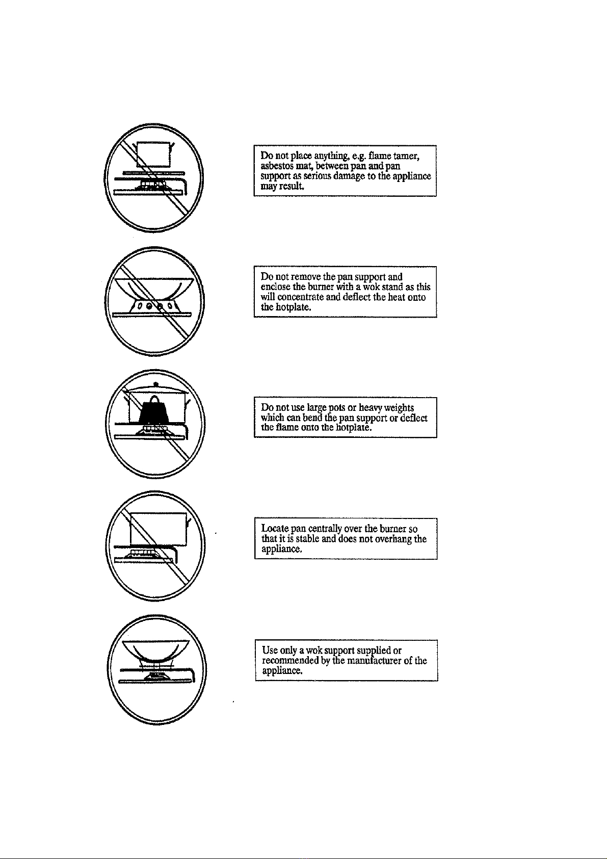
The followings should be avoid:
- Obstructing the ventilation or heat dissipation
- Allowing the power supply cord of other appliances to come into contact with the hot surface of the
cooktop
- Exposure to atmospheric agents (rain, sun)
- Using flammable liquids nearby
- Using unstable or deformed cookware
- Trying to install or repair the appliance without the assistance of qualified personnel.
6
How to Use Your Appliance
The position of the corresponding gas burner is indicated on each control knob.
GAS BURNERS
The burners differ in size and power. Choose the most appropriate one according to the diameter of the
cookware being used.
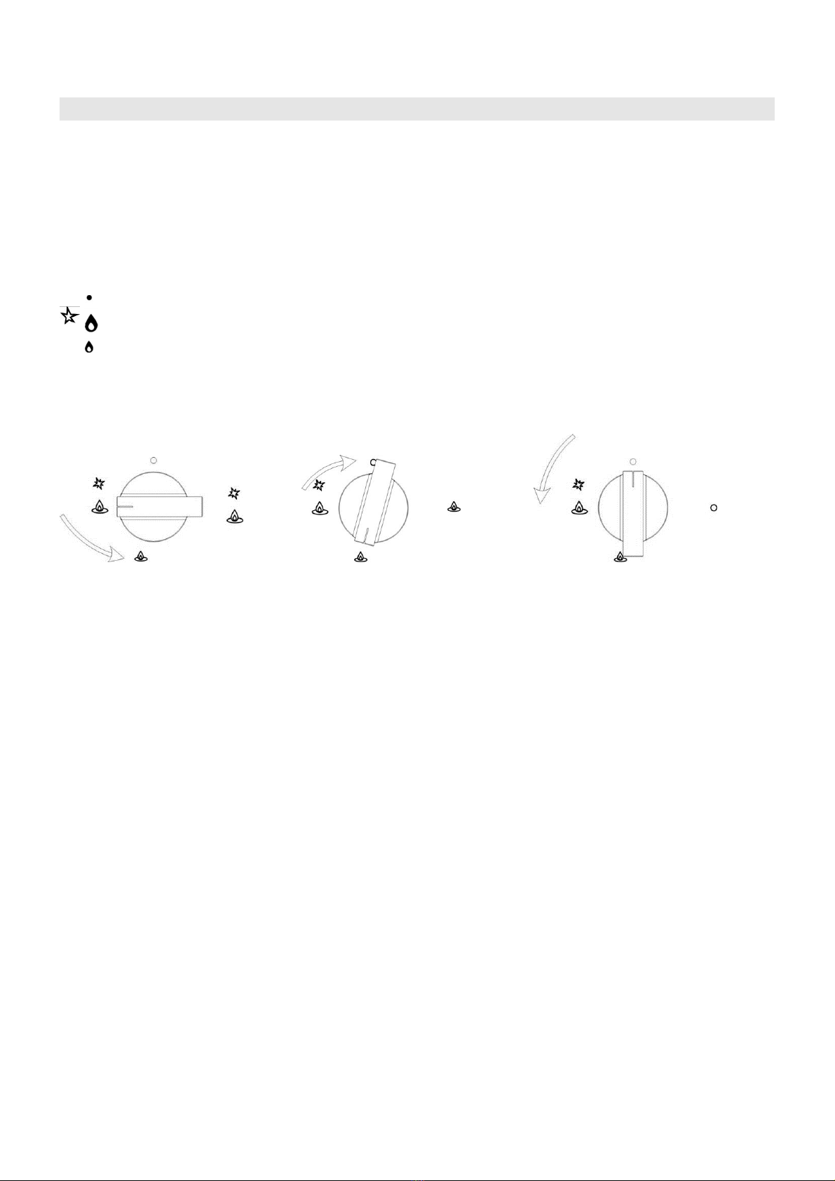
The burner can be regulated with the corresponding control knob by using one of tile following settings:
OFF (close valve)
High (maximum aperture or flow)
Low (minimum aperture or flow)
If the burners adjusted correctly, the flames should be light blue, and the inner cone should be clearly visible.
The size of flame depends on the position of the related burner control knob.
-Burner ON,large flame -Burner ON,small flame(saving mode)-Burner OFF
The burner should be set at a large flame during the initial phase of cooking to bring the food to boiling, and
then the knob should be turned to the saving flame position to maintain the cooking. It is also possible to
adjust the flame size stepless.
It is prohibited to adjust the flame in the range between the Burner OFF and Burner ON large flame
positions.
Significant quantities of energy can be saved if the appliance is used correctly, parameters set correctly, and
appropriate cookware is used. The savings can be as follows:
· Up to 60 per cent savings when proper pots are used,
· Up to 60 per cent savings when the unit is operated correctly and the suitable flame size is chosen.
It is a prerequisite for efficient and energy-saving operation of the cooktop that the burners are kept clean at all
times (in particular the flame slots and nozzles).
IGNITING THE BURNERS
The appliance comes with auto ignition and safety device. Proceed as follows to ignite the burner:
1. Turn the chosen knob in anti-clockwise direction to the “High” setting.
2. Push in and hold the knob for 5 to 8 seconds to permit the thermocouple to heat up
3. Release the knob after the gas burner is lit
4. Adjust the flame as desired by turning the control knob
Repeat point 1 and 2 if the flame cannot be lighted.

7
Caution:
The ignition device shall not be operated for more than 15 seconds. If after 15 seconds the burner has still not been
lighted, stop operating the device and wait for at least 1 minute before attempting a further ignition of the burner.
If the flame accidently goes out, the safety valve will automatically cut out the gas flow. To re-ignite the burner, turn
the control knob back to “OFF” setting and wait for at least I minute before attempting a further ignition of the burner.
Turn off a burner, turn the knob in clockwise direction until it stops (it should be on the "." setting).
BATTERY IGNITION
If the auto ignition does not work, make sure that the battery (1.5V), installed at the back of the cooker, is not
flat and has been installed correctly.
CHOICE OF THE BURNERS
It is important that the diameter of the pots and pans suitably match the heating potential of the burners in
order not to jeopardize the efficiency of the burners, bringing about a waste of gas fuel. Avoid having flames
extending out from underneath the pans (refer to the table). When the content comes to a boiling condition,
turn the knob to “Low”. A smaller diameter pot or pan placed on a larger burner does not necessarily mean that
the boiling conditions are reached quicker.
Table of recommended pans
Burner Ø Pan diameter in cm
Auxiliary
Semi rapid
Rapid
Triple ring
from dia. 8 to dia. 14
from dia. 14 to dia. 20
from dia. 20 to dia. 28
Above dia. 26
AUTOMATIC SAFETY VALVES
This safety device automatically closes the gas valve should theflame goes off for some reasons.
TRIPLE RING BURNER
The triple ring burner must be correctly positioned (seen fig.1); the burner rib must be entered in their lodgment
as shown by the arrow. The burner correctly positioned must not rotate (fig.2).
Then position the cap A and the ring B (fig.2).
Fig 1 Fig 2

8
Cleaning and Maintenance
Cleaning and maintenance should be carried out after the appliance has turned cold especially when cleaning
burner and the cast iron support. Avoid leaving alkaline or acid substances (lemon juice, vinegar etc.) on the
surfaces. Avoid using acid or chlorine-based cleaning products.
To extend the life of the cooktop, it is absolutely indispensable that the appliance be
cleaned carefully and thoroughly on a frequent basis, keeping in mind the following:
CAST IRON PARTS, All of the cast iron parts must be washed only with a sponge and soapy water or
with non-abrasive products
BURNERS AND GRIDS These parts can be removed and cleaned with appropriate products. After
cleaning, the burners and their flame distributors must be well dried and correctly replaced. It is very
important to check that the burner flame distributor F and the cap Chas been correctly positioned (fig. 3)
-failure to do so can cause serious problems.
Check that the electrode “S” (fig.3) is always clean to ensure trouble-free sparking. Check that the probe”
T” (fig.3) is always clean to ensure correct operation of the safety valves. Both the probe and ignition plug
must be very carefully cleaned
Note: regular use could cause discoloring around the burners due to high flame temperature.
Fig 3
F
C
C

9
CLEANING THE TRLPLE RING BURNER
Pay special attention to this burner: the burner crown must always be kept clean. When cleaning, remove the
flame divider (fig.4) and use a cotton bud, toothbrush or some other item to clean out any incrustations or dirt
from the four holes marked “H” (fig.5). This procedure is necessary to ensure the burner functions correctly.
GAS TAPS
Periodic lubrication of the gas taps must be carried out by specialist personnel only. In the event of operating
faults in the gas taps, call the Service Department.
GENERAL ADVICE
√ When the appliance is not being used; it is advisable to keep the gas tap closed.
√If the gas tap becomes stiff, it is necessary to dismount it accurately, clean it with gasoline and spread a
bit of special grease resistant to high temperatures on it. This operation must be executed by a qualified
technician.
Greasing the Gas Valves
Over time, the gas valves may become difficult to turn. If this is the case, the inside of the valve must be
cleaned and grease.
N.B.: This procedure must be performed by a technician authorized by the manufacturer.
Fig 4 Fig 5

10
Advice for the Installer
IMPORTANT:
The appliance should be installed, regulated and adapted to function with other types of gas by a
QUALIFIED INSTALLATION TECHNICIAN. Failure to comply with this condition will render the guarantee
invalid.
The appliance must be installed in compliance with regulations in force in your country and in observation
of the manufacturer’s instructions.
Always unplug the appliance before carrying out any maintenance operations or repairs.
Some appliances are supplied with a protective film on steel and aluminum parts. This film must be
removed before using the cooker.
The appliances must be housed in heat resistant units
The walls of the units must not be higher than work top and must be capable of resisting temperatures of
75°C above temperature.
Do not install the appliance near inflammable materials (eg.curtain).
TECHNICAL INFORMATION
The cooktops are designed to be embedded into kitchen fixtures measuring 600 mm in depth.
In order to install the cook top into the kitchen fixture, a hole with the dimensions shown at the cutting size
board has to be made, keeping in consideration the following:
√within the fixture, between the bottom side of the cooker top and the upper surface of any other
appliance or internal shelf, there must be a clearance of at least 30 mm (fig.7);
√the cooker top must be kept no less than 100 mm away from any side wall;
√the hob must be installed at least 50mm away from the rear wall.
√there must be a distance of at least 650 mm between the hob and any wall cupboard or extractor hood
positioned immediately above (fig.6).
√It is essential to install a heat baffle between the bottom of the hob and the underlying unit.
√Clamps are provided to fasten the appliance to the kitchen fixture measuring from 20 to 60mm in
thickness. To fasten the cooktop securely, it is recommended that all the clamps to be used.

11
INSTALLATION IN KITCHEN CABINET WITH DOOR (fig.7)
The fixture has to be made according to specific requirements in order to prevent the gas burners from going
out, even when the flame is turned down to minimum, due to pressure changes while opening or closing the
cupboard doors. It is recommended that a 30 mm clearance be left between the cooker top and the fixture
surface (fig.7).
fig.6
12
CHOOSING SUITABLE SURROUNDINGS
The room where the gas appliance is to be installed must have a natural flow of air so that the gas can burn.
The flow of air must come directly from one or more openings made in the out-side walls with a free area of at
least 100c㎡. If the appliance does not have a no-flame safety device this opening must have an area of at
least 200c㎡.
The openings should be near the floor and preferably on the side opposite the exhaust for combustion
products and must be so made that they cannot be blocked from either the outside or the inside. When these
openings cannot be made the necessary air can come from an adjacent room which is ventilated as required,
as long as it is not a bedroom or a dangerous area. In this case the kitchen door must allow the passage of the
air.
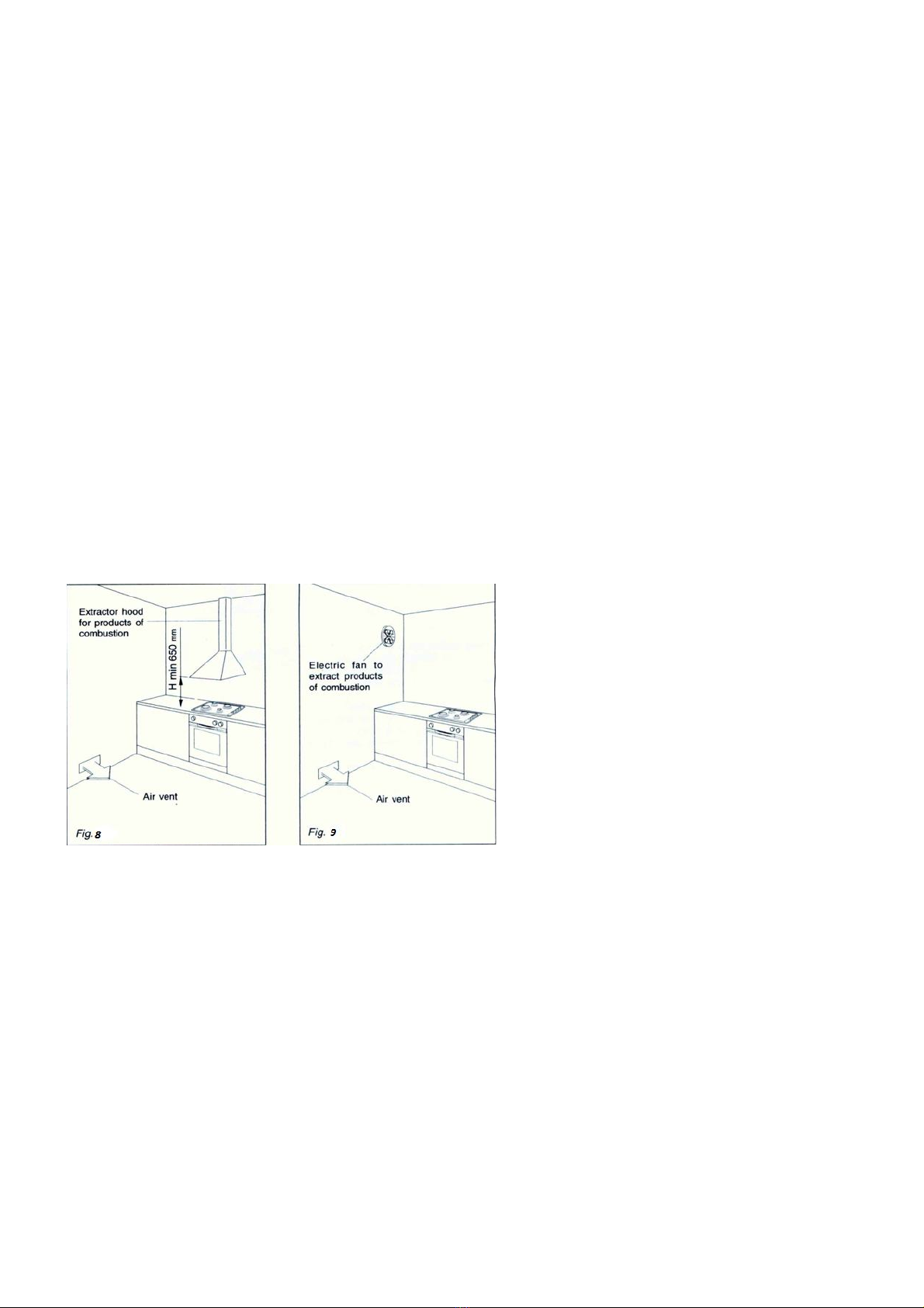
DISCHARGING PRODUCTS OF COMBUSTION
Extractor hoods connected directly to the outside must be provided, to allow the products of combustion of the
gas appliance to be discharged (fig.8). If this is not possible, an electric fan may be used, attached to the
external wall or the window; the fan should have a capacity to circulate air at an hourly rate of 3-5 times the
total volume of the kitchen (fig.9). The fan can only be installed if the room has suitable vents to allow air to
enter, as described under the heading “choosing suitable surroundings”
SETTLING UP THE HOB FOR INSTALLATION
Every cooker top is provided with a set of tabs for fitting to the fixture panel with thickness from 3 to 4 cm and a
seal with adhesive on one side.
-Remove burners and grids.
-Turn the cooker top over and rest the glass side on a cloth.
- Place the battery in the battery compartment.
-Apply the self-adhesive seal “G” as illustrated in fig.10.
-Slot the cooker top into the unit and position.
-Position the cooker top in the recess and secure by means of the brackets as shown in fig.11 (for 3 or 4
cm thick work top).

13
CUT-OUT DIMENSION
Different models cut-out dimension are different, please be ensure to use the correct dimension to installation.
Model Cut Out Dimension(mm) Height
EFH7622 HM VGB (670~725mm)×(370~410mm)
75mm
EFH7632 HM VGB (670~725mm)×(370~410mm)
75mm
EFH9721 HM VGB (670~825mm)×(370~435mm)
75mm
EFH9731 HM VGB (670~825mm)×(370~435mm)
75mm
EFH7622 HM VGB & EFH7632 HM VGB EH9721 HM VGB & EFH9731 HM VGB
Fig 12

14
Gas Section
TYPES OF GASES
The gases normally used may be grouped, in view of their features in three families:
-L.P.G. (in cylinders) G30
-NATURAL GAS (methane) G20
-CITY GAS G110
IMPORTANT:
The appliance should be installed, regulated and adapted to function with other types of gas by a QUALIFIED
INSTALLATION TECHNICIAN.
INSTALLATION
The appliance is predisposed and adjusted to operate with the gas indicated on the specifications plate applied
onto the appliance.
If the appliance must be operated with a gas different than that indicated on the plate, it is necessary to execute
the following operations:
-replacement of the injectors
-regulating of the minimum
GAS CONNECTION FOR GAS HOB
The Cooker should be connected to the gas-supply by licensed installer. During installation of this product it is
essential to fit an approved gas tap to isolate the supply from the appliance for the convenience of any
subsequent removal or servicing. Connection of the appliance to the gas mains or liquid gas must be carried
out according to the prescribed regulation in force, and only after it is ascertained that it is adaptable to the type
of gas to be used. If not, follow the instructions indicated in the paragraph headed “Adaptation to different gas
types”. In the case of connection to liquid gas, by tank, use pressure regulators that conform to the regulation
in force.
Connection to the gas course must be done in such a way that not to create any stress points at any part of the
appliance
IMPORTANT: For safety, for the correct regulation of gas use and long life of the appliance, ensure that the
gas pressure conforms to the indications given in table 1 “Nozzle and burner characteristics”.
ORIENTATION OF THE ELBOW
The appliance is supplied with a gas connection oriented towards the center of the cooking hob. The
connection to the gas supply must be effected only from this side or in vertical position by turning the elbow
downwards. To turn the elbow, follow these operations:
√Loosen the nut √Turn the elbow √Lock the nut √Make sure there is no leakage by a soapy solution.
SEAL CHECK
After connecting to the mains, check that all the couplings are correctly sealed, using soap solution. NEVER
use a naked flame

15
IMPORTANCES:
√Prior to installation, ensure that the local distribution conditions (nature of gas and gas pressure) and
the adjustment of the appliance is compatible
√Never attempts to turn the elbow without having first slackened off the relative lock nipple.
√ The seals are the elements that guarantees the seal in the gas connection. It is recommended that they
be replaced whenever they show even the slightest deformation or imperfection.
√Ensure that all the couplings are correctly sealed.
√The connection with rigid metal pipes should not cause stresses to the hob ramp.
√If the rubber tube is used for the gas connection:
-Make sure the tube is snugly fit at both ends and use a standard tube clamp (not supplied) to fasten it.
-The rubber tube must be as short as possible, without contractions or kinks.
-The rubber tube must never be at any point in its length in contact with the “hot” parts.
-From time to time check to make sure that the rubber is in perfect condition.
√This appliance is not connected to a combustion product evacuation device. It shall be installed and
connected in accordance with current installation regulations. .Special attention shall be given to the
relevant requirements regarding ventilation.
Note: In case of glass breakage of the cooktop, shut off all burners immediately and isolate the
appliance from the gas supply. Do not touch the appliance and DO NOT use the appliance. Call
customer service department for assistance.
REGULATING THE BURNER MINIMUM SETTING
Please ensure the minimum flow rate of the burner is correctly adjusted. The flame should not go out even
when passing suddenly from maximum to minimum flame. To regulate the flame follow the instructions below:
√Light the burner
√Set the cock valve to minimum
On gas valves provided with adjustment screw in the center of the shaft (fig.15)
√ Using a screwdriver with maximum diameter of 3mm, turn the screw inside the tap until the correct
setting is obtained.
On gas valves provided with adjustment screw on the valve body (fig.16):
√Turn the screw “A” to the correct setting with a screwdriver. Normally for G30 gas, fully tighten the
adjustment screw.

16
LUBRICATION OF THE GAS TAPS
If the gas tap becomes stiff, it is necessary to dismount it accurately clean it with gasoline and spread a bit of
special grease which resistant to high temperatures on it.
The operations must be executed by a qualified technician.
INSTALLING THE BATTERY
Insert a DC1.5V battery into the battery compartment (see below fig 17, fig 18) in the cover. This battery is the
power supply for the electronic ignition of gas burners.
Notes for battery installation or replacement:
•Only use a DC1.5Volt battery (size “D”)
•Check for correct polarity ( label to the side of the battery compartment).
Important notes:
•Remove the battery if the cooker is not going to be used for a long time.
•If the battery leaks, replace it immediately.
Avoid touching the leaked liquid and make sure it does not come into contact with clothes or other items.
•Clean the battery compartment carefully before installing the new one.
•Note: The battery is a potential source of danger for children. Keep them away.
•Dispose of flat batteries properly.

17
SELF CHECK
In the event of any abnormal occurs during operation of the gas hob or the gas hob does not function properly,
you may do a self check before contacting customer service officer. Disconnect the hob from gas connection
before checking.
- Check that there is no interruptions in the gas and battery supply and make sure that the gas valves are
open
- If burner cannot be lighted or the flame is not distributed evenly, make sure the followings:
oNo clog on the burners’ gas holes
oThe burners and the cap is correctly mounted
oNo strong air flow around the cooking area
oThe ignition method is correct (refer to page 6, “Igniting the burners”)
- If the flame cannot hold when the setting is turned to “Low” , make sure the followings:
oNo clog on the burners’ gas holes
oThe minimum gas flow is adjusted correctly (refer to page 16, “Regulating the burner minimum
settings”)
oNo strong air flow around the cooking area
- In the event that the cookware is not well balance when sit on the burner, make sure the followings:
oThe bottom of the cookware is perfectly flat
oThe cookware is sit correctly on the burner
oThe support grids is well sat on the burner base
When consulting the customer service center, please ensure that you have the model number, date of
purchase and repair issue ready.

18
The manufacturer and agent decline all responsibilities in the event of
damage caused by improper, incorrect or illogical use of the appliance.
Contact after sales service center when in doubt of the condition of the
appliance.
For after sales service [Singapore], please contact
Casa (S) Pte Ltd
15 Kian Teck Crescent, Singapore 628884
Telephone: +65 6268 0077
Fax: +65 6898 0510
Email: service@casa.com.sg
This manual suits for next models
3
Table of contents
Other EF Hob manuals


Popular Hob manuals by other brands


AEG
AEG 600 M OPERATING AND INSTALLATION Manual

Siemens
Siemens EX8 NV Series INFORMATION FOR USE

Teka
Teka IZ 6320 Installation instructions and recommendations for using and maintaining

AEG
AEG 6453 K8 operating instructions

Kuppersbusch
Kuppersbusch KI9810.0SF Instructions for use and installation

Award
Award H102B Instructions of use


