Efergy ecotouch User manual
INSTRUCTION MANUAL
ECOTOUCH
ENERGY MANAGEMENT SYSTEM
At the end of its serviceable life, this product should not be treated as household general waste. It should be handed over to the
applicable collection point for the recycling of electrical equipment, or returned to the supplier for disposal.
*All values shown in this manual are only examples. Actual figures will vary depending on your consumption.

WE RECOMMEND THAT YOUR ELECTRICITY MONITOR IS INSTALLED BY A QUALIFIED ELECTRICIAN
CONTENTS INTRODUCTION
INTRODUCTION
SAFETY
IN THE BOX
HARDWARE INSTALLATION
Prior to Installation
Mounting Individual or Multiple Circuits
Installing the Mini CT Sensor
SETTINGS
Your ecotouch Monitor
Voltage and Carbon Ratio
Tariffs
Alarm, Time and Date
Temperature and Currency
Control
Master Reset and Link
MONITOR MODES
How to Change Modes
FAQS
TECHNICAL INFORMATION
INSTALLATION NOTES
The ecotouch energy management system wirelessly measures the amount of energy that
you are using in your home and displays the data in simple, easy to understand information.
The ecotouch enables you to view your energy data in different modes, with options for
viewing historical, current or summarized data. The ecotouch not only acts as a display but
a control point, where you can turn appliances on and off through the ecosockets.
Ask George
If you have any questions about using your installation or further information on saving
energy, you can contact George or visit our website. We aim to answer all your emails within
48 hours.
Email your questions to:
info.aus@efergy.com
Email your technical questions to:
askgeorge@efergy.com
Efergy Customer Service:
(+61) 1300 799 851
www.efergy.net.au
2
3
5
6
7
9
11
12
13
14
15
16
17
18
20
21
22
2

IMPORTANT SAFETY INFORMATION
It is important that you take some simple precautions before using this product. Incorrect use
or poor safety practices can result in injury or fatality. Whenever possible, turn off the main
breaker outside your home feeding power to your electric panel.
When installing the ecotouch energy management system you should find that everything is
straight-forward. However, there are a number of important health and safety issues which
you need to be aware of:
Mini CT sensor clip fits onto the internal live feed cable inside the electricity meter, which
delivers the live supply to your home.
Do not touch any metallic connections during the installation of the mini CT sensor. Do not
carry out this installation if under the influence of alcohol or drugs.
Remember the device is not intrusive and does not require rewiring; no wires or cables need
to be cut, removed or modified to perform this installation. If you notice anything unusual
about the electricity supply such as loose wires, exposed cabling, burn marks, holes in the
insulating materials or damage to the electric wires in the service panel or where the mini CT
sensor is to be attached, stop immediately and report the findings to your supply company.
efergy energy monitoring systems are considered plug and play devices that meet all
regulatory requirements for installation in Australia.
Do not force or bend the cables at any point during installation. If you are worried or have
any concerns about the installation, please contact a qualified electrician immediately. Only a
qualified electrician can access the live cable in Australia.
•
•
•
•
•
•
•
•
•
3 4
The mini CT sensor is not run by batteries and so does not need to be removed from the
electricity panel for the life of the unit. The transmitter requires 3xAA batteries, and the
ecotouch monitor charges through the ecosockets or your computer using a USB cable.
Even with the main breaker in the off position, the connection lugs where the main wires
terminate at the main breaker may still be live with potentially lethal voltage. Stay clear of
these connections during the installation of the mini CT sensor, see page 9.
The mini CT sensor itself is insulated so do not be concerned if it slides down the main wire
to the breaker after being secured around the insulated wire. A plastic tie wrap (with 5cm of
the tie not cut off) secured to the main wire under the desired location for the sensor may be
used to keep the sensor from sliding down the wire.
Millions of these systems have been installed worldwide without incident but please follow
safe work practices as outlined during the installation.

WE RECOMMEND THAT YOUR ELECTRICITY MONITOR IS INSTALLED BY A QUALIFIED ELECTRICIAN
IN THE BOX HARDWARE INSTALLATION
65
Your ecotouch management system contains:
1 x ecotouch display
1 x ecosocket
1 x transmitter
1 x elink software CD
1 x mini CT sensor
1 x USB cable
PRIOR TO INSTALLATION
The efergy ecotouch system is installed by clipping the mini CT sensor around the feed wire of
your electric panel. In Australia the standard residential voltage is 240V.
Note - For a 240V panel (typical residential electric panel) power is measured using one mini CT
sensor. For different voltages, please change during the Monitor Setup stage (see page 13).
Installation for Three Phase Panels
The ecotouch system is installed by clipping the mini CT sensors around the feed wire of your
electric panel. In the case of a commercial or industrial three phase panel or service, you must
use three mini CT sensors to measure all three phases. Simply order an additional two mini
CT sensors from your dealer. Identify the three power wires providing service to your electric
panel. Open and place one sensor around each of the three main feed wires.
Installing Transmitter for Three Phase
Plug the three mini CT sensor cables into the transmitter. Mount the transmitter on the wall next
to the electric panel. This will make it easier to replace the batteries. Readings for a three phase
system may not be accurate depending on connection and loading system.
EXIT
ENERGY MANAGEMENTSOFTWARE
For Windows XP, Vista,Windows 7 ( 32 & 64 bit )
Mac OSX 10.5+
System Requirements:
Min 800x600 or above - Java V6.0+
Adobe Air V1.5+
2.0
10 / 15 / 20s
ELECTRICITY MONITORING
TRANSMITTER

HARDWARE INSTALLATION HARDWARE INSTALLATION
7 8
Locate Your Electrical Panel
Locate your electricity meter and determine its type. You
can normally find this on an outside wall, in the garage,
basement or utility room. If you live in a flat, it can often
be found outside your front door, in the communal
stair case, or in the basement. Ensure there is enough
of accessible cable coming from the bottom of your
electricity meter.
Modern office blocks and apartments may have
safety panels to protect wires entering the meter. It
is recommended that professional electricians be
contacted where this is the case.
Find the Main Feed Wires for Your Home
You should find four cables exiting the meter (see both
Fig. 1 and Fig. 2). The feed cable (cable 4) is the live
cable exiting from the meter to the fuse box. Connect
the mini CT sensor to cable 4. Some installations will
have cable 1 and cable 2 covered or partially covered
to prevent any tampering with the supply (see Fig. 2). In
this case you will still attach the sensor to cable 4.
Dual Tariff Meters
Dual Tariff meters (shown in Fig. 3) will often have an auxiliary cable running between cable 3
and cable 4. Auxiliary cables will be smaller in diameter than the feed cables, and will run into
an adjoining metering device.
Newer installations will normally have two cables exiting from the bottom of the meter. One is
the earth cable, the other the live feed cable. The mini CT sensor should be clipped around the
live feed cable (this is normally brown coloured).
If you have a three phase supply, or economy 7 meter, then you may require additional sensors.
These can be simply plugged into the additional sockets at the base of the transmitter. Please
contact your supplier for additional sensors.
Auxilary Cable
1
2
3
4
1234
Fig. 1
Fig. 3
123
4
Fig. 2
MOUNTING INDIVIDUAL OR MULTIPLE CIRCUITS
WE RECOMMEND THAT YOUR ELECTRICITY MONITOR IS INSTALLED BY A QUALIFIED ELECTRICIAN
HARDWARE INSTALLATION
109
HARDWARE INSTALLATION
The sensor needs to be fitted to the live feed cable. Mini CT sensors are suitable for cables up
to 12mm in diameter. You should not force the cable to fit. The sensor should fit loosely around
the cable and there should be no packing used.
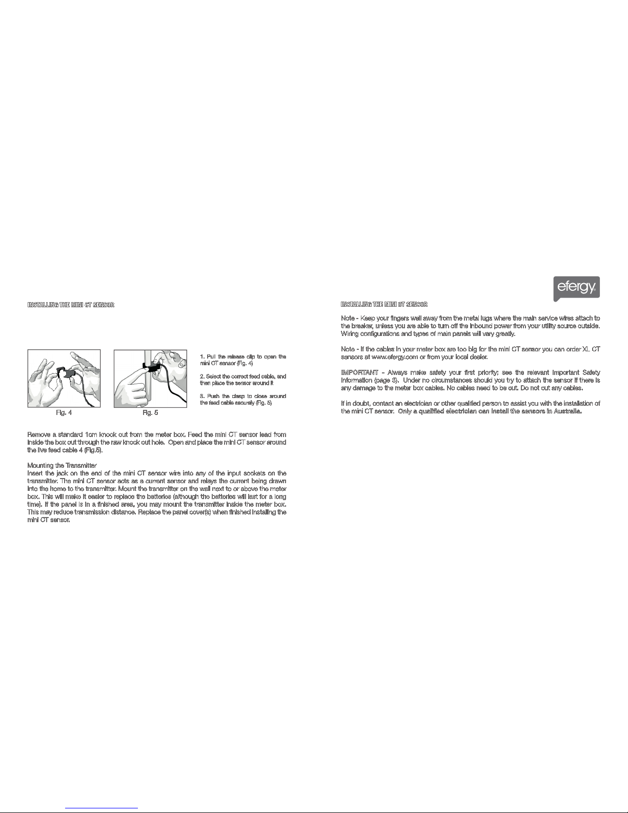
Remove a standard 1cm knock out from the meter box. Feed the mini CT sensor lead from
inside the box out through the raw knock out hole. Open and place the mini CT sensor around
the live feed cable 4 (Fig.5).
Mounting the Transmitter
Insert the jack on the end of the mini CT sensor wire into any of the input sockets on the
transmitter. The mini CT sensor acts as a current sensor and relays the current being drawn
into the home to the transmitter. Mount the transmitter on the wall next to or above the meter
box. This will make it easier to replace the batteries (although the batteries will last for a long
time). If the panel is in a finished area, you may mount the transmitter inside the meter box.
This may reduce transmission distance. Replace the panel cover(s) when finished installing the
mini CT sensor.
INSTALLING THE MINI CT SENSOR
INSTALLING THE MINI CT SENSOR
Fig. 4 Fig. 5
1. Pull the release clip to open the
mini CT sensor (Fig. 4)
2. Select the correct feed cable, and
then place the sensor around it
3. Push the clasp to close around
the feed cable securely (Fig. 5)
Note - Keep your fingers well away from the metal lugs where the main service wires attach to
the breaker, unless you are able to turn off the inbound power from your utility source outside.
Wiring configurations and types of main panels will vary greatly.
Note - If the cables in your meter box are too big for the mini CT sensor you can order XL CT
sensors at www.efergy.com or from your local dealer.
IMPORTANT - Always make safety your first priority; see the relevant Important Safety
Information (page 3). Under no circumstances should you try to attach the sensor if there is
any damage to the meter box cables. No cables need to be cut. Do not cut any cables.
If in doubt, contact an electrician or other qualified person to assist you with the installation of
the mini CT sensor. Only a qualified electrician can install the sensors in Australia.
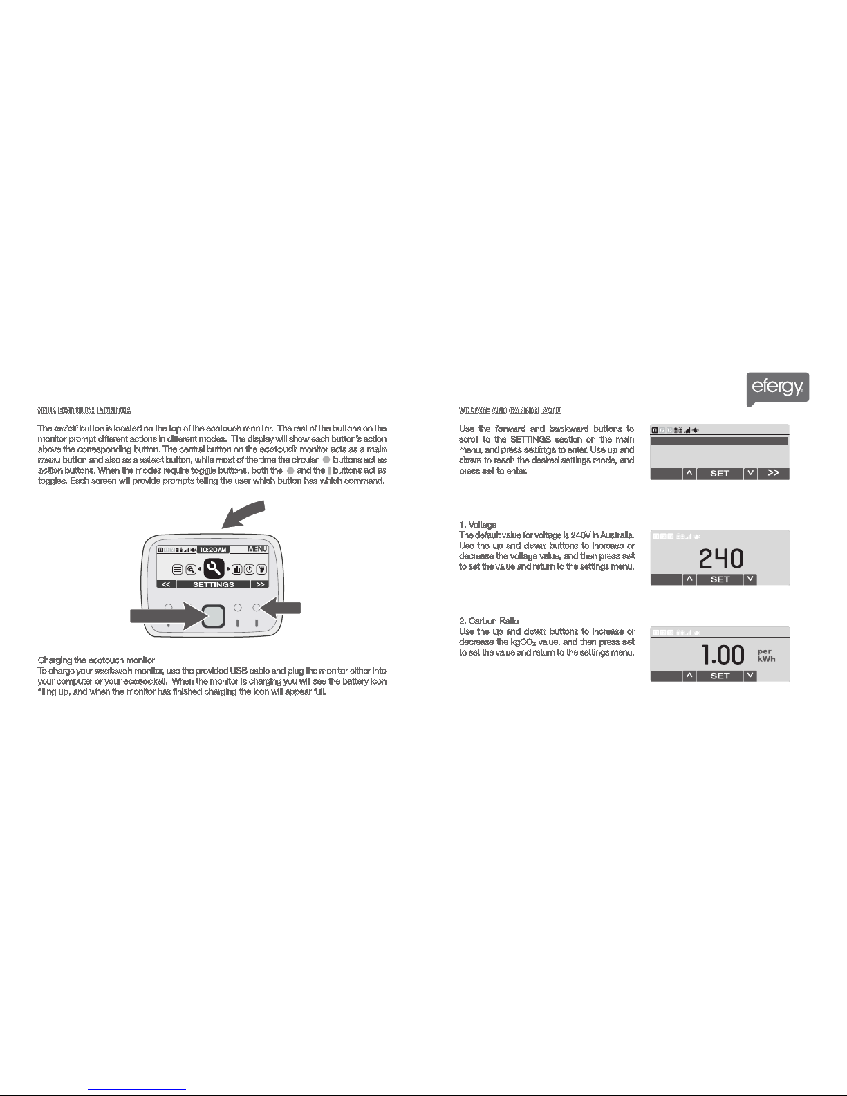
Use the forward and backward buttons to
scroll to the SETTINGS section on the main
menu, and press settings to enter. Use up and
down to reach the desired settings mode, and
press set to enter.
1. Voltage
The default value for voltage is 240V in Australia.
Use the up and down buttons to increase or
decrease the voltage value, and then press set
to set the value and return to the settings menu.
2. Carbon Ratio
Use the up and down buttons to increase or
decrease the kgCO2value, and then press set
to set the value and return to the settings menu.
SETTINGS SETTINGS
11 12
YOUR ECOTOUCH MONITOR VOLTAGE AND CARBON RATIO
Charging the ecotouch monitor
To charge your ecotouch monitor, use the provided USB cable and plug the monitor either into
your computer or your ecosocket. When the monitor is charging you will see the battery icon
filling up, and when the monitor has finished charging the icon will appear full.
The on/off button is located on the top of the ecotouch monitor. The rest of the buttons on the
monitor prompt different actions in different modes. The display will show each button’s action
above the corresponding button. The central button on the ecotouch monitor acts as a main
menu button and also as a select button, while most of the time the circular buttons act as
action buttons. When the modes require toggle buttons, both the and the buttons act as
toggles. Each screen will provide prompts telling the user which button has which command.
On/Off
Action
Main Menu
EXIT
EXIT
Voltage
V
EXIT
EXIT
Carbon Ratio
kg
CO
2
2. Carbon Ratio
3. Tariff
4. Alarm
Choose setting
EXIT
1. Voltage
WE RECOMMEND THAT YOUR ELECTRICITY MONITOR IS INSTALLED BY A QUALIFIED ELECTRICIAN
SETTINGS SETTINGS
13
TARIFFS
14
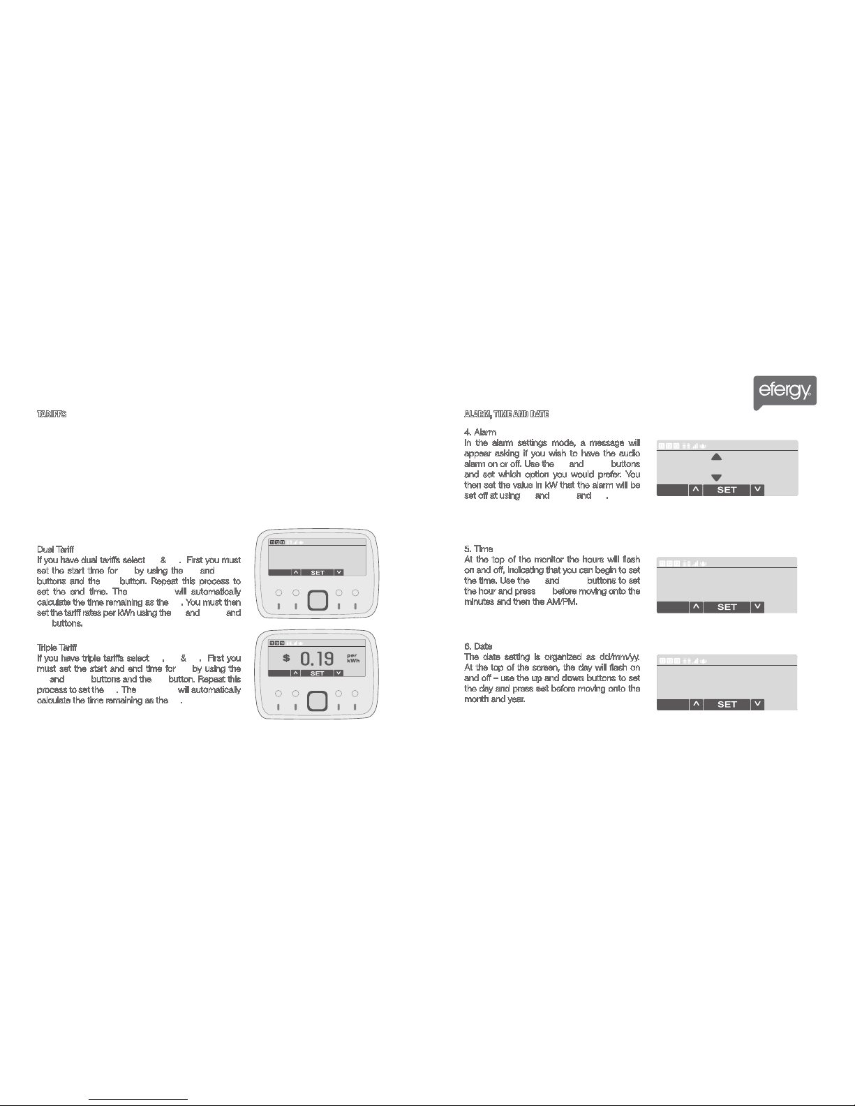
6. Date
The date setting is organized as dd/mm/yy.
At the top of the screen, the day will flash on
and off – use the up and down buttons to set
the day and press set before moving onto the
month and year.
3. Tariff
In the top left-hand corner of the tariff settings there are three icons, T1, T2, and T2, indicating
your tariff mode. Use the up and down buttons to toggle between the modes. If you have a
single tariff, select just T1, if you have dual tariffs select T1 & T2, if you have triple tariffs select
T1, T2 & T3.
Single Tariff
If you have a single tariff, select T1, and then use the up and down and set buttons to set your
tariff per kWh.
Dual Tariff
If you have dual tariffs select T1 & T2. First you must
set the start time for T1 by using the up and down
buttons and the set button. Repeat this process to
set the end time. The ecotouch will automatically
calculate the time remaining as the T2. You must then
set the tariff rates per kWh using the up and down and
set buttons.
Triple Tariff
If you have triple tariffs select T1, T2 & T3. First you
must set the start and end time for T1 by using the
up and down buttons and the set button. Repeat this
process to set the T2. The ecotouch will automatically
calculate the time remaining as the T3.
ALARM, TIME AND DATE
5. Time
At the top of the monitor the hours will flash
on and off, indicating that you can begin to set
the time. Use the up and down buttons to set
the hour and press set before moving onto the
minutes and then the AM/PM.
4. Alarm
In the alarm settings mode, a message will
appear asking if you wish to have the audio
alarm on or off. Use the up and down buttons
and set which option you would prefer. You
then set the value in kW that the alarm will be
set off at using up and down and set.
EXIT
EXIT
Tariff
EXIT
EXIT
Tariff
EXIT
EXIT
10.20AM
EXIT
EXIT
10/04/2011 Day
EXIT
EXIT
Alarm
5.00 kW
SETTINGS SETTINGS
15 16
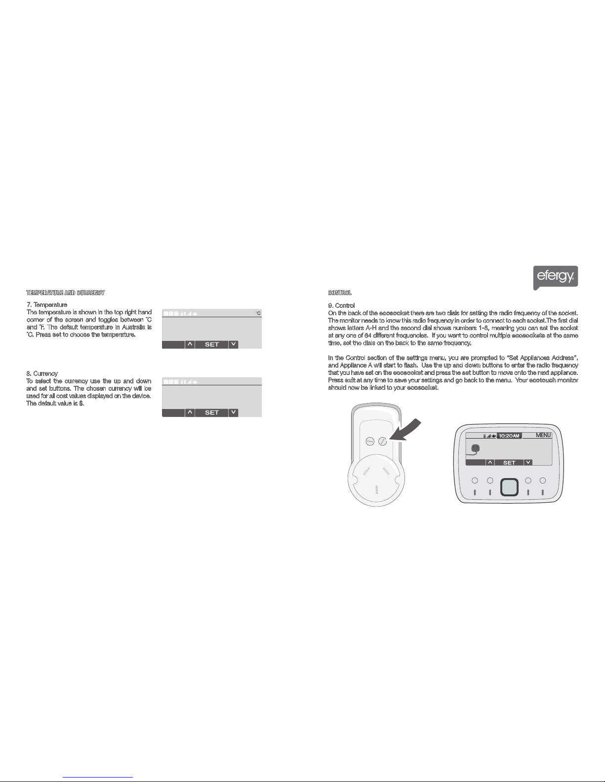
9. Control
On the back of the ecosocket there are two dials for setting the radio frequency of the socket.
The monitor needs to know this radio frequency in order to connect to each socket.The first dial
shows letters A-H and the second dial shows numbers 1-8, meaning you can set the socket
at any one of 64 different frequencies. If you want to control multiple ecosockets at the same
time, set the dials on the back to the same frequency.
In the Control section of the settings menu, you are prompted to “Set Appliances Address”,
and Appliance A will start to flash. Use the up and down buttons to enter the radio frequency
that you have set on the ecosocket and press the set button to move onto the next appliance.
Press exit at any time to save your settings and go back to the menu. Your ecotouch monitor
should now be linked to your ecosocket.
7. Temperature
The temperature is shown in the top right hand
corner of the screen and toggles between ˚C
and ˚F. The default temperature in Australia is
˚C. Press set to choose the temperature.
8. Currency
To select the currency use the up and down
and set buttons. The chosen currency will be
used for all cost values displayed on the device.
The default value is $.
TEMPERATURE AND CURRENCY CONTROL
EXIT
EXIT
EXIT
EXIT
$
Radio
Frequency
EXIT
A = A1
Set Appliances Address
EXIT
WE RECOMMEND THAT YOUR ELECTRICITY MONITOR IS INSTALLED BY A QUALIFIED ELECTRICIAN
17 18
MASTER RESET AND LINK HOW TO CHANGE MODES
SETTINGS MONITOR MODES
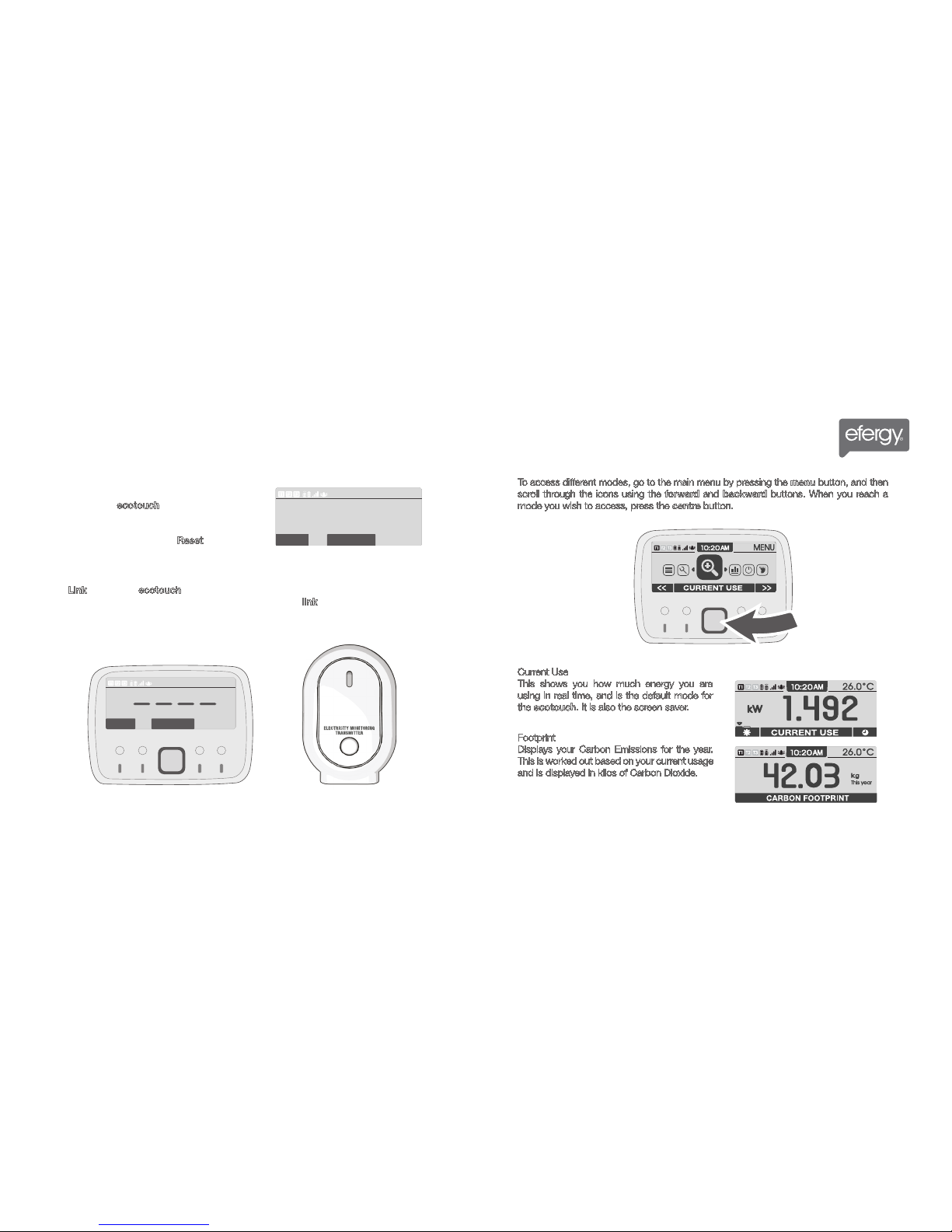
To access different modes, go to the main menu by pressing the menu button, and then
scroll through the icons using the forward and backward buttons. When you reach a
mode you wish to access, press the centre button.
Current Use
This shows you how much energy you are
using in real time, and is the default mode for
the ecotouch. It is also the screen saver.
Footprint
Displays your Carbon Emissions for the year.
This is worked out based on your current usage
and is displayed in kilos of Carbon Dioxide.
10. Master Reset
This settings option will completely delete all saved
data from your ecotouch monitor. A warning
message will appear when you enter this setting,
advising you to only proceed if you want to clear all
data previously collected. Press Reset to continue.
11. Link?
Press Link to link your ecotouch monitor to your transmitter. Four dashes will show while the
device is linking, and a message will read “linking...”. Press the link button on the transmitter to
complete synchronization. If the link is completed the monitor will display “Link OK” message.
EXIT
EXIT
Master Reset
RESET
This will delete all the saved
information on this device
EXIT
EXIT
EXIT
EXIT
LikeDevice?
LINK
EXIT
2019
MONITOR MODES
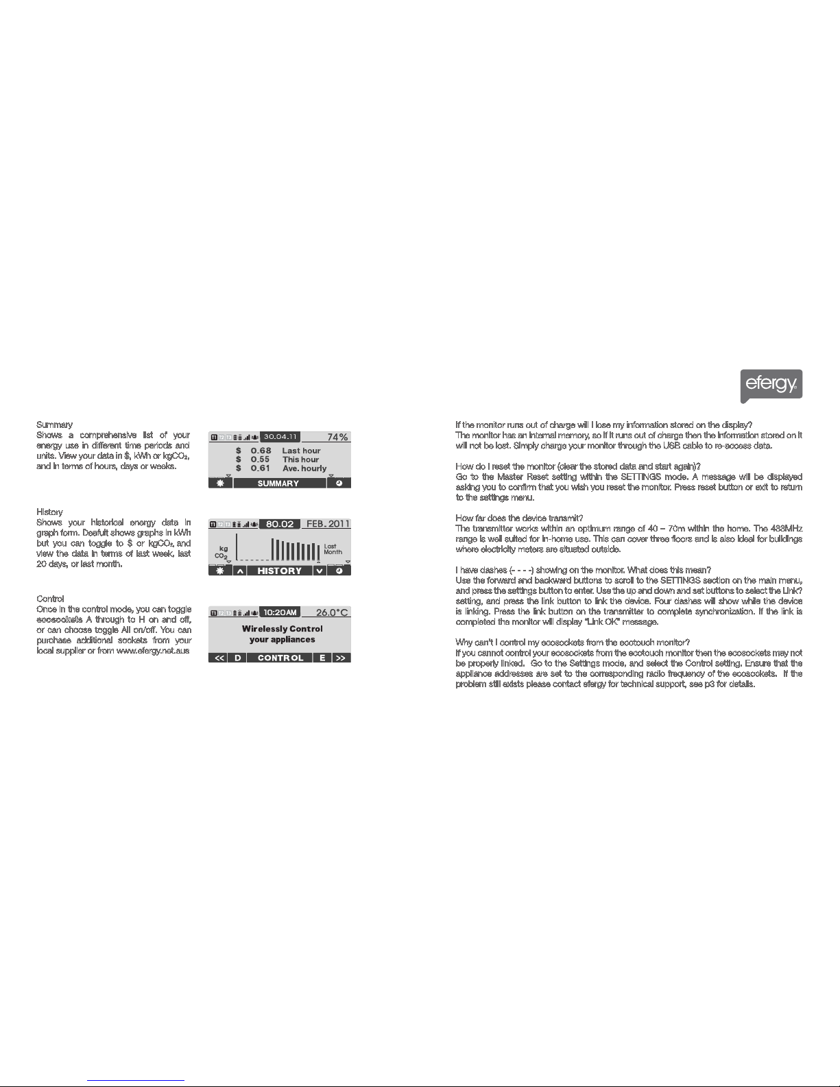
Summary
Shows a comprehensive list of your
energy use in different time periods and
units. View your data in $, kWh or kgCO2,
and in terms of hours, days or weeks.
History
Shows your historical energy data in
graph form. Deafult shows graphs in kWh
but you can toggle to $ or kgCO2, and
view the data in terms of last week, last
20 days, or last month.
Control
Once in the control mode, you can toggle
ecosockets A through to H on and off,
or can choose toggle All on/off. You can
purchase additional sockets from your
local supplier or from www.efergy.net.aus
FAQS
If the monitor runs out of charge will I lose my information stored on the display?
The monitor has an internal memory, so if it runs out of charge then the information stored on it
will not be lost. Simply charge your monitor through the USB cable to re-access data.
How do I reset the monitor (clear the stored data and start again)?
Go to the Master Reset setting within the SETTINGS mode. A message will be displayed
asking you to confirm that you wish you reset the monitor. Press reset button or exit to return
to the settings menu.
How far does the device transmit?
The transmitter works within an optimum range of 40 – 70m within the home. The 433MHz
range is well suited for in-home use. This can cover three floors and is also ideal for buildings
where electricity meters are situated outside.
I have dashes (- - - -) showing on the monitor. What does this mean?
Use the forward and backward buttons to scroll to the SETTINGS section on the main menu,
and press the settings button to enter. Use the up and down and set buttons to select the Link?
setting, and press the link button to link the device. Four dashes will show while the device
is linking. Press the link button on the transmitter to complete synchronization. If the link is
completed the monitor will display “Link OK” message.
Why can’t I control my ecosockets from the ecotouch monitor?
If you cannot control your ecosockets from the ecotouch monitor then the ecosockets may not
be properly linked. Go to the Settings mode, and select the Control setting. Ensure that the
appliance addresses are set to the corresponding radio frequency of the ecosockets. If the
problem still exists please contact efergy for technical support, see p3 for details.
WE RECOMMEND THAT YOUR ELECTRICITY MONITOR IS INSTALLED BY A QUALIFIED ELECTRICIAN
TECHNICAL INFORMATION
2221
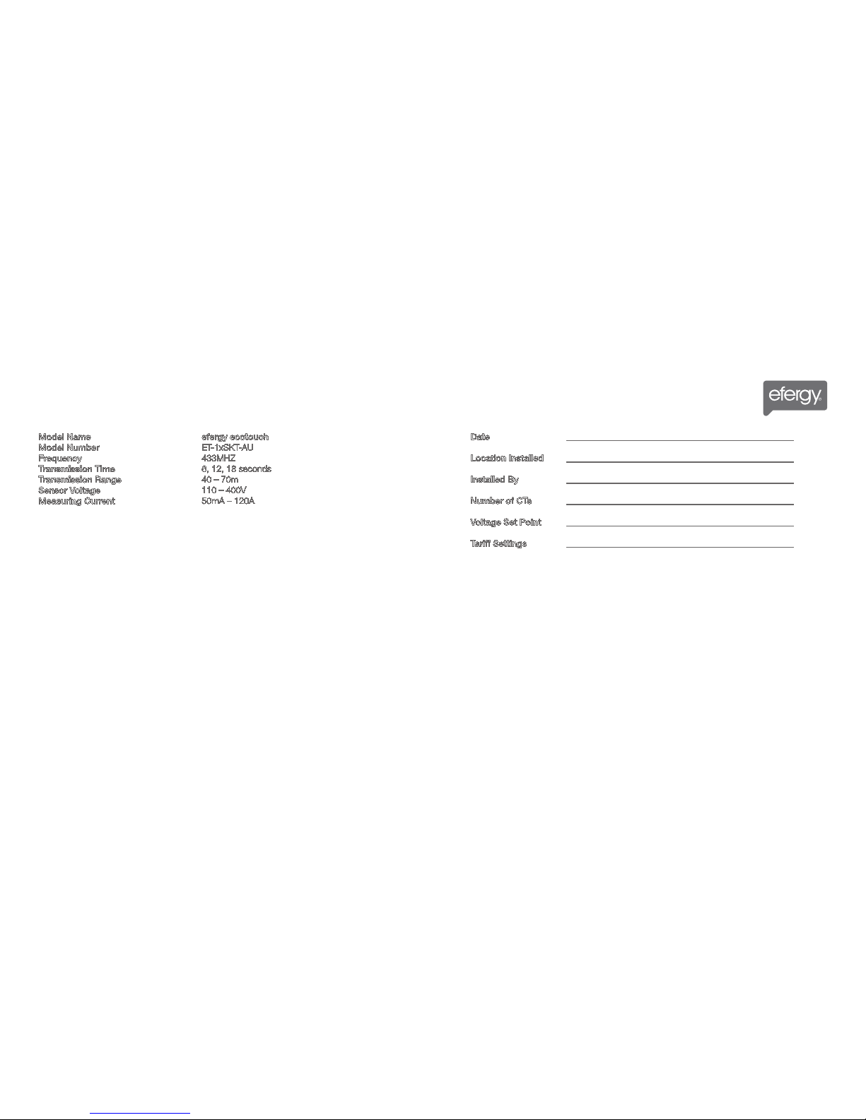
INSTALLATION NOTES
Date ___________________________________________________
Location Installed ___________________________________________________
Installed By ___________________________________________________
Number of CTs ___________________________________________________
Voltage Set Point ___________________________________________________
Tariff Settings ___________________________________________________
Model Name
Model Number
Frequency
Transmission Time
Transmission Range
Sensor Voltage
Measuring Current
efergy ecotouch
ET-1xSKT-AU
433MHZ
6, 12, 18 seconds
40 – 70m
110 – 400V
50mA – 120A
Table of contents
Other Efergy Household Appliance manuals


Popular Household Appliance manuals by other brands


pols potten
pols potten Taro in pot 540-300 Series instruction manual

Orion
Orion Bloo Septic Tank Maintenance manual

Velux
Velux DK-2950 user manual

Tekky
Tekky PUMPKIN GUARDIAN OF THE GRAVE Installation and operating instructions

Cucine Oggi
Cucine Oggi Back Liner 240 x 900 Assembly instructions

PawHut
PawHut D08-025V70 Assembly & instruction manual