Effekta EPS-D V2 User manual
1
V1.2
MANUAL FOR EMERGENCY POWER SUPPLY
EPS-D V2

2
Content
1. Safety . . . . . . . . . . . . . . . . . . . . . 3
2. Presentation . . . . . . . . . . . . . . . . . 3
3. Functional description . . . . . . . . . . . . 4
4. Commissioning . . . . . . . . . . . . . . . . 5
5. Programming . . . . . . . . . . . . . . . . . 6
Setting the number of outputs . . . . . . . . . . . . .6
Type of output . . . . . . . . . . . . . . . . . . . . . .6
Application of priority levels . . . . . . . . . . . . . .7
Time setting of priority levels . . . . . . . . . . . . . .7
Set warning level for low battery voltage . . . . . . .8
Perform a complete system test . . . . . . . . . . . .9
6. Schematics . . . . . . . . . . . . . . . . . . 9
7. Technical data . . . . . . . . . . . . . . . .10
8. Battery mounting . . . . . . . . . . . . . . .11
9. Troubleshooting. . . . . . . . . . . . . . . .11
10. Menu tree . . . . . . . . . . . . . . . . . .12
V1.2
Manual Emergency Power Supply EPS-D
Installation, planning and service

3
!i
1. Safety
Only authorized and experienced personnel in AC/DC are allowed to use, work, service/maintain,
and install this device.
Only insulated tools are permitted to be used within the device.
Please note that dangerous voltages and currents exist within the device, both when the
internal fuses are on or off.
This manual should be thoroughly read and understood by all personnel who handle the device.
If there is any doubt about the system’s structure, function, components, or safety, the supplier
should be contacted.
2. Presentation
EPS-D is an emergency power supply unit for operating emergency lighting xtures, providing 100%
voltage during emergencies, for at least 60 minutes. Fixtures with incandescent bulbs, LEDs, uorescent
tubes, or compact uorescent tubes can be freely mixed in the same installation. Fixtures with
conventional drivers, known as magnetic drivers, can be combined with xtures that have HF drivers
(Note: connected drivers should have Cos /Power factor > 0.8).
The unit consists of a primary switched charging rectier at 24V DC, an inverter, and built-in batteries. The
batteries used are maintenance-free lead batteries with an estimated lifespan of 10-12 years. EPS works
as an off-line UPS, so during normal power supply, the inverter is unloaded and only the batteries are
maintained. This is very energy-efcient and provides an efciency of approximately 98%.
SAFETY: The unit is protected against overload and short circuit. The mains, load, and battery are
protected by fuses
EPS-D automatically performs a battery test and inverter test once a day at the preset time on the timer.
INDICATIONS AND ALARMS: Mains voltage is indicated on the display front. Alarm relay A is for mains
voltage failure, and alarm relay B is for inverter failure. Alarm1 is for insulation failure, and Alarm 2 monitors
the output loops. The alarm relays have potential-free switching contacts.
APPROVAL: Meets the requirements of EN-50 171 and is CE approved.
If you change the power at any
output, a system test must be
carried out!
ON/OFF
This is only for restarting the
device, a complete test is not
performed.

4
*There needs to exist a connection between AL1 com-AL2 NC in order to obtain a summary alarm from
Com AL2 and NC AL1. This summary alarm indicates mains failure and changes in the load
3. Functional description
The incoming single-phase 230V AC is converted through the primary switched power module inside the
EPS-D unit into a DC charging voltage of 27.4V, 2-10A depending on the model (see table, page 10). The
DC voltage then feeds the battery with a DC voltage level that is factory adjusted to the correct level, via
2-pole MCB for battery connection.
The inverter is driven by 24V and is secured with a fuse. It also has a built-in fan. The deep discharge relay
breaks the voltage at about 21.5V during battery operation. The alarm relay monitors the output voltage of
the inverter and provides a potential-free relay output in case of a fault.
The incoming AC voltage is fused with glass tube fuses and then feeds the power module and a UPS
relay that switches between mains voltage and the inverter. This voltage is then forwarded to a distribution
board with 4 or 8 outputs where you can choose different functions.
During normal power supply, the mains voltage is directly connected to the distribution board via the UPS
relay. At the same time, the batteries are charged, and the inverter is in idle mode.
When the mains voltage disappears, the UPS relay switches to the inverter, which now supplies the
outputs with clean sine-wave voltage. The switchover time is about 15ms.
Every day, a shorter self-test is performed when the pre-programmed timer breaks the input voltage and
starts the inverter. This is done at 6:00 a.m. and lasts for ve minutes. If you want to change the factory
settings, contact Effekta service and support department.
Once a year, a full test is performed when the inverter performs a self-test that lasts for 60 minutes. If it
fails to last for 60 minutes of battery operation, the battery fault indicator will ash and the alarm relay will
switch. If everything is in order, the inverter will return to normal operation.
The outputs should be programmed for either safety luminaries, exit luminaries, lighting luminaries, or
always off, or only during normal power supply
Alarm outputs
🡲 EPS-D - Has multiple alarm functions and alarm outputs.
🡲 Alarm output type A - Mains failure alarm
🡲 Alarm output type B - Inverter failure alarm
🡲 Alarm output Alarm-1* - Output relay that alarms for an insulation fault
🡲 Alarm output Alarm-2* - Fault or interruption in the lighting loop
🡲 IN1 - Turns on everything (Normally Open)
🡲 IN2 - Turns on OUT1 (Normally Open)
🡲 EPS-D - has the following protections:
🡲 Short-circuit protection
🡲 Overload protection
🡲 Deep discharge protection
🡲 Fuses for incoming mains
🡲 Fuses for each output
🡲 Automatic fuse for inverter and batteries
🡲 Maximum cable distance: 400 m / 2.5 mm²
🡲

5
Program clock
T1 Adjusting the charging voltage
+ -
BATTERY
24V
INVERTER
START
Mains in
I N
NP230VAC
A-LARM B-LARM
C No NC C Nc No
PL7
REP
Fl-1
Fl-2
PL1 PL8
N
P
P1
P2
P4
K2
K1
R4
R3 R2
D4
D3
D2
D6 RE5
+24VØV ØV Batt +Inv 24V
P3
PL2
F2-1
D1
LED
PL6
M1
M2
PL4
230VAC
INV
RE4
POWC2
RE3
PL3
REG
REL
Alarm type A Mains failure alarm
Alarm type B Inverter failure alarm
BATTERY PLUS
BATTERY MINUS
FAN PLUS
FAN MINUS
PE (GROUND)
+5V
RX
TX
GND
SCL
SDA
GND
GND
IN1
GND
IN2
MAIN 230V
MAIN 230V
NO
NO
NC
NC
COM
COM
SUPPLY ON/OFF
BUTTONS DISPLAY
TEMPERATURE
SENSOR
GND +5V
OUT
LEDs
OUT1
LEDs
OUT2
LEDs
OUT3
LEDs
OUT4
LEDs
OUT5
LEDs
OUT6
LEDs
OUT7
LEDs
OUT8 EMERGENCY
LIGHTS
CONTROLLER
M1-8
LN
LEAK
CURREN
SENSOR
OUT1 OUT2 OUT3 OUT4 OUT5 OUT6 OUT7 OUT8
NL NL NL NL NL NL NL NL
EMERGENCY 230V AC
EMERGENCY
NET 230V
EMERGENCY
NET 230V
UART 12C INPUTS ALARM 1 ALARM 2
Jord
Noll
Fas
Fas
Noll
nät
UPS ut
4. Commissioning
🡲 Connect the outgoing cables to terminals 1 to 8.
The terminals for the outputs can accommodate
up to 2.5mm² cable area. Tighten the screws
properly! And check all internal cables/wires!
🡲 Connect 230V AC to the ”MAIN IN” terminal
🡲 NOTE! There is no ON/OFF button on the device,
which means that the device starts when the
battery fuse is switched on.
🡲
🡲 Check that the charging voltage is correct. Adjust
if necessary.
🡲 Check the output voltage and current to your
luminaries.
🡲 Check that the display on the front is lit and that
no alarms are active before programming the
outputs
🡲
Connecting an EPS-D V2

6
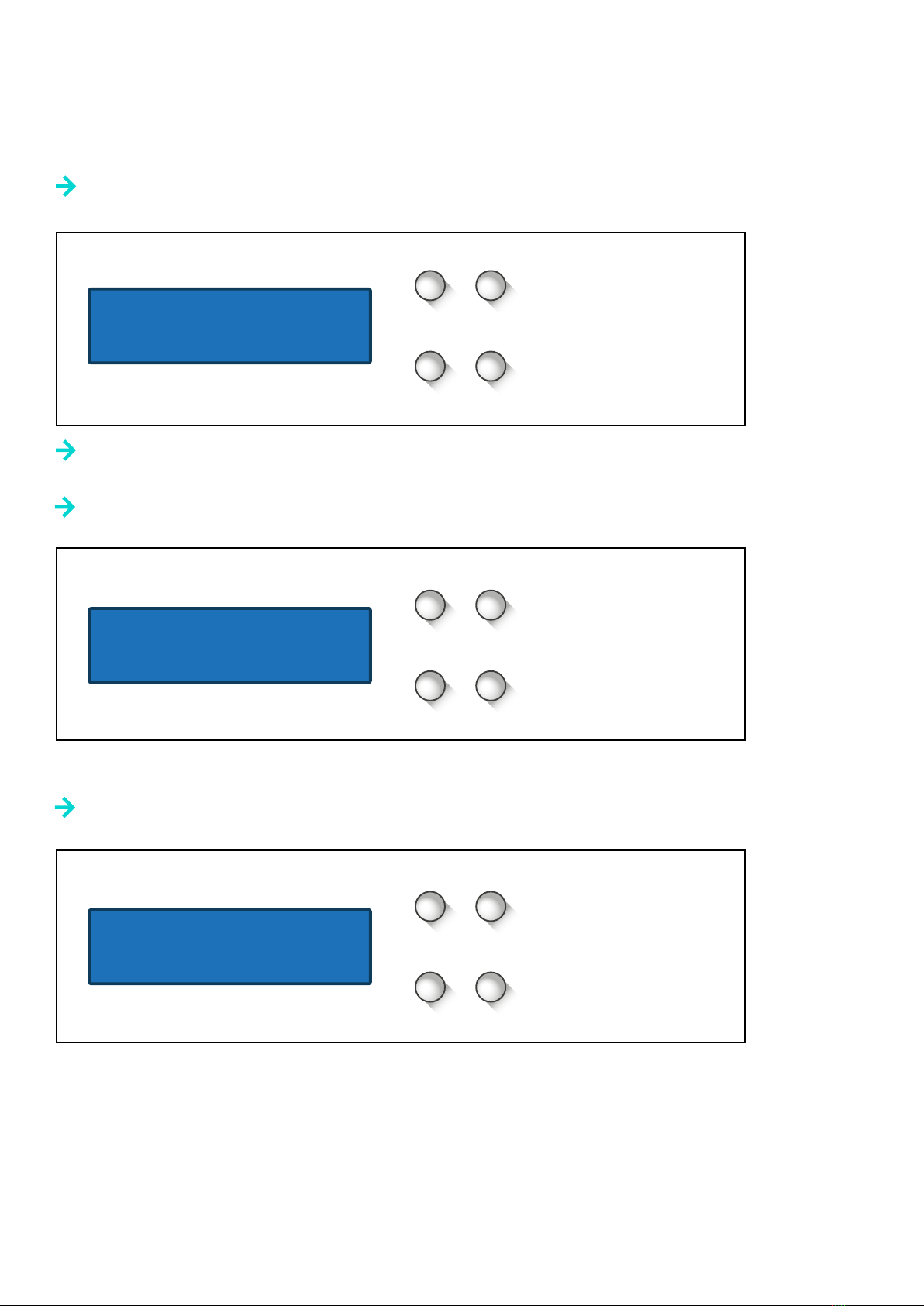
5. Programming
Setting the number of outputs
Press the ”Menu” button until the screen displays:”
M
E
+
-
Then press the ”E” button. Next, a prompt will appear asking for the password.
The default password is 0000, then press the ”E” button to conrm.
Press the ”M” button again until you reach the following screen
M
E
+
-
Here, you can use the ”+” and ”-” buttons to select the desired number of outputs.
Once you have selected the correct number, press the ”Enter” button to conrm.
Type of output
Here, you can select whether the output should be reference, emergency, constantly off,
or only during mains operation. Complete the previous steps rst. Then, press the ”M” button
until you reach the following screen:
M
E
+
-
Select which output you want to change by pressing the ”+” or ”-” buttons, and then press the ”E” button
to select that output. Once you have selected the output, use the ”+” and ”-” buttons again to change the
type of output. When you have made your selection, press the ”E” button to conrm it
MODE=>Feed
ENTER=>Settings.
Desired number of
Outputs
X
X
Type of output

7
Setting priority levels
Press the ”M” button until you reach the following screen:
M
E
+
-
Here, you can select the output you want to change the priority for by using the ”+” and ”-”
buttons and then pressing ”E”. Once you have selected an output, you can choose the
priority level for it using the ”+” and ”-” buttons and then pressing ”E”.
Setting the time for the priority levels
This is the time that the outputs should have emergency power in case of power failure.
NOTE: Default is 60 minutes! Click on M until you reach the following screen:
M
E
+
-
Select the output you want to set the time for by using the ”+” and ”-” buttons and
then press ”Enter”. Use the ”+” and ”-” buttons to set the time you want for the priority level and
then press ”Enter” to conrm.
Repeat this process for any other outputs you want to set the time for.
Priority. High
Time X min
Priority of output
X High
8
Setting the warning level for low battery voltage
The minimum battery voltage is set to warn the system when the battery capacity has dropped.
M
E
+
-
Use the + and - buttons to adjust to a suitable level, preferably 22.5V for a 24V battery system.
Then conrm the choice by pressing the ”E” button
Once the settings are completed, exit the menu by clicking on the “M” button until you return to
the main view.
M
E
+
-
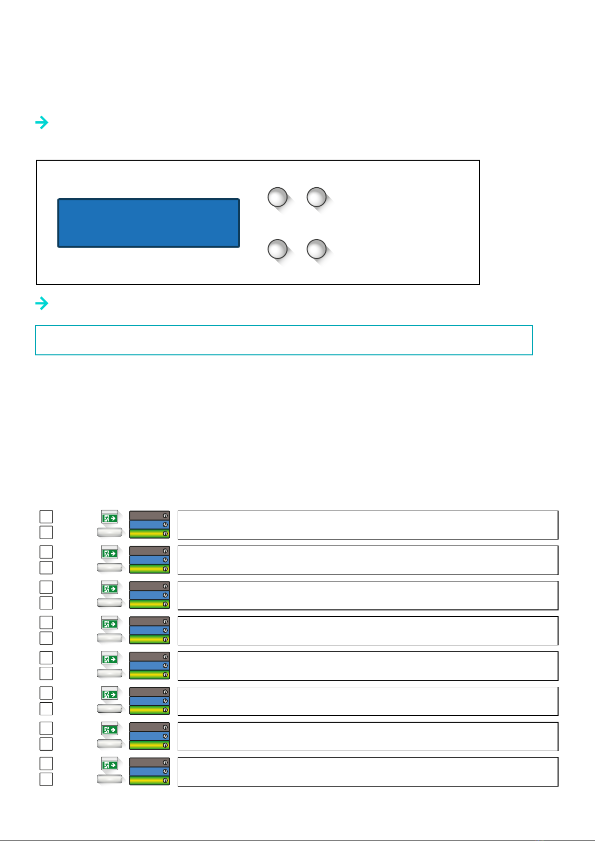
Click on “E” to go to the next view. In the next view, click on “M” until you come to a menu
that in a faultless system looks like this:
M
E
+
-
Minimum battery
voltage 10,00V
MODE=>Settings
ENTER=>Feed
No errors
OK
9
Hänvisning
Nödljus
Hänvisning
Nödljus
Hänvisning
Nödljus
Hänvisning
Nödljus
Hänvisning
Nödljus
Hänvisning
Nödljus
Hänvisning
Nödljus
Hänvisning
Nödljus
Conduct a full system test
This test checks all outputs and their power, to detect if any xtures are malfunctioning.
Click on “M” until you reach the following screen:
M
E
+
-
Click on “E” to start the test.
NOTE: The test must always be performed as soon as the load on any of the outputs has changed!
After following the steps above, the setup is complete, and the product is ready to be used.
System test
Start => ENTER
Exit
Safety
Exit
Safety
Exit
Safety
Exit
Safety
Exit
Safety
Exit
Safety
Exit
Safety
Exit
Safety
6. Schematics

10
7. Technical data
Art. nr Product In/Out Battery Mass Dimensions
302040 EPS-D V2 150W 230VAC 12Ah 24 kg 400 x 600 x 250 mm
302041 EPS-D V2 400W 230VAC 24Ah 38 kg 400 x 600 x 250 mm
302042 EPS-D V2 600W 230VAC 45Ah 55 kg 400 x 600 x 250 mm
302043 EPS-D V2 1000W 230VAC 65Ah 82 kg 600 x 800 x 300 mm
302044 EPS-D V2 1500W 230VAC 100Ah 100 kg 600 x 800 x 300 mm
302045 EPS-D V2 2000W 230VAC 120Ah 120 kg 600 x 800 x 300 mm
TECHNICAL DATA
302040 302041 302042 302043 302044 302045
Rated voltage normal
operation
230 VAC 230 VAC 230 VAC 230 VAC 230 VAC 230 VAC
Rated frequency normal
operation
50/60 Hz 50/60 Hz 50/60 Hz 50/60 Hz 50/60 Hz 50/60 Hz
Charging time <15h <15h <15h <15h <15h <15h
Lead batteries 10-12 years 2 x12V 12Ah 2 x12V 24Ah 2 x12V 45Ah 2 x12V 65Ah 2 x12V 100Ah 2 x12V 120Ah
Rated operating power
emergency operation
150W 400W 600W 1000W 1 500W 2 000W
Operating temperature -10° - +25° C -10° - +25° C -10° - +25° C -10° - +25° C -10° - +25° C -10° - +25° C
Operating time in
emergency operation
>1h >1h >1h >1h >1h >1h
Protection class IP 21 IP 21 IP 21 IP 21 IP 21 IP 21
Number of outputs 4 4 4 8 8 8
INTERNAL FUSES
Type F1-1,F1-2 F2-1 (BLADSÄKRING) F1-4 ( F1-8) S5,S6
Mains fuse Inverter fuse Load fuse Battery fuse
302040
150W
2 AT 15A 6,3As 10 AT
302041
400W
4 AT 20A 6,3As 16 AT
302042
600W
5AT 30A 6,3As 25 AT
302043
1000W
6AT 5A 6,3As 40AT
302044
1500W
10AT 5A 6,3As 63 AT
302045
2000W
10AT 5A 6,3As 2x40 AT
(Bridged)

11
9. Troubleshooting
🡲 Mains power failure indicated – check input
voltage and primary fuse F1-1, F1-2. Replace fuse
if necessary. If the fuse blows again, check the
connected equipment.
🡲 Low battery voltage alarm - Check the
batteries.
🡲
🡲
🡲
🡲
🡲 Inverter alarm – check the input voltage to the
inverter module. If there is 24VDC input voltage
to the inverter, check the output voltage which
should be 230VAC. If input voltage is present and
output voltage is missing – turn off the switch on
the right side of the inverter, wait 20 seconds and
turn it on again. If the problem persists, replace
the inverter module
🡲 Inverter alarm and the unit is beeping –
conduct troubleshooting according to text above
🡲
8. Battery mounting
For service, we recommend batteries as below.
Battery options
EPS-D V2 600W 230VAC 45Ah UPLUS US12-45 Leoch LPC12-45
EPS-D V2 1000W 230VAC 65Ah UPLUS US12-65 Leoch LPL12-65
EPS-D V2 1500W 230VAC 100Ah UPLUS USC12-100 Leoch LPL12-100
EPS-D V2 2000W 230VAC 120Ah UPLUS USC12-120 Leoch LPL12-120

12
Effekta Power Systems
Prästtorpsvägen 16
341 51 Lagan, Sweden
+46 (0)40-94 60 20
effekta.se
info@effekta.se
i
MODE
MODE
MODE
MODE
MODE
X
20C
20C
PLUS
MINUS
X
Correct PIN
MODE
MODE
MODE
MODE
PLUS
MINUS
ENTER
PLUS
MINUS
X
MODE
MODE
TEXT1
TEXT2
MODE
X mA
MODE
MODE
MODE
MODE
MODE
MODE
ENTER
(save)
ENTER
(save)
ENTER
(save)
ENTER
(save)
PLUS
MINUS
TEXT ENTER (save)
PLUS
MINUS
XENTER (save)
PLUS
MINUS
XTEXT
ENTER ENTER (save)
PLUS
MINUS
XTEXT
ENTER ENTER (save)
PLUS
MINUS
TEXT1 TEXT2
ENTER ENTER (save)
PLUS
MINUS
XENTER (save)
PLUS
MINUS
XENTER (save)
PLUS
MINUS
XENTER (save)
PLUS
MINUS
XENTER (save)
PLUS
MINUS
XENTER (save)
PLUS
MINUS
XENTER (save)
MODE
PLUS
MINUS
X1
ENTER
(insert)
ENTER
(insert)
ENTER
(insert)
ENTER
(insert)
Incorrect PIN
ENTER
X2 X3 X4
X1 X2 X3 X4
M1- MENU
g
MODE=> Measurement
ENTER => Settings
MODE =>Settings
ENTER => Measurement
Enter password
X1X2X3X4
New Password
X1X2X3X4
web to Vb48.0V At
10,0A Et 480W
Output
Au 3,0A Eu 150W
No error
OK
Temp.Sens.1
Temp.Sens.2
Language
English
Number of active
outputs X
X
TEXT
Type of output
Output priority
XTEXT
Priority
Time
maximum
Leakage current
Minimum battery
voltage XV
Maximal power
deviation X%
System test
Enter
=> ENTER ENTER (starta)
Current correction
At 10,0A kX
Voltage correction
Vb48,0V k X
Background light.
time.Xs
If you change the power at any output, a
system test must be carried out!
This is only for restarting the device, a
complete test is not performed.
If you change the power at any
output, a system test must be
carried out!
!
🡲 Menu tree as shown in figure.
Effekta Power Systems reserves itself for any factual
or typographical errors in this printed matter.
Manual EPS-D V2 2313-1-Eng
10. Menu tree
ON/OFF
This is only for restarting the
device, a complete test is not
performed.
This manual suits for next models
6
Table of contents
Other Effekta Power Supply manuals


