Effemme WIZARD UP 30 M User manual
Wizard Up30 M Rev. 0 01/02/2018
Pag. 1
SINGLE SCISSOR
MOBILE LIFT
WIZARD
UP 30 M
HTC S.r.l.– Via degli Elettricisti – Zona Ind.le Scerne - 64025 Pineto (TE)
Tel. 085.9463008 – Fax 085.9462461 Web site www.effemmelifts.com - E-mail info@effemme.biz - P.Iva:
01607910674

Wizard Up30 M Rev. 0 01/02/2018
Pag. 2
INDEX
1 – INTRODUCTION............................................................................................................................ 3
2 – GENERAL SAFETY AND ACCIDENT PREVENTION STANDARDS ............................................ 3
2.1 – WORKING PLACE .................................................................................................................. 4
3 –WIZARD UP30M LIFT DESCRIPTION ........................................................................................... 5
3.1 – TECHNICAL FEATURES ........................................................................................................ 6
3.2 –CE PLATE ................................................................................................................................ 9
3.3 – SAFETY PICTOGRAMS.......................................................................................................... 9
3.4 –CONDITIONS OF THE WORKING AREA.............................................................................. 12
4 – INSTALLATION AND OPERATION OF THE LIFT....................................................................... 12
4.1 – RECEIPT AND PACKAGING HANDLING............................................................................. 12
4.2 – STORAGE ............................................................................................................................. 14
4.3 – UNPACKING ......................................................................................................................... 14
4.4 – MACHINE INSTALLATION.................................................................................................... 14
4.5 – HYDRAULIC PLANT CONNECTION .................................................................................... 15
4.6 – ELECTRIC PLANT CONNECTION ....................................................................................... 18
4.7 – FIRST OPERATION .............................................................................................................. 21
4.8 – USE ....................................................................................................................................... 22
4.9 – EMERGENCY........................................................................................................................ 23
5 – RESIDUAL RISKS........................................................................................................................ 23
6 – MAINTENANCE ........................................................................................................................... 25
6.1 – GENERAL RULES................................................................................................................. 25
6.2 – SPECIFIC RULES ................................................................................................................. 26
6.2.1 – RECOMMENDED OIL..................................................................................................... 26
6.3 – CLEANING ............................................................................................................................ 26
7 – DISMANTLING............................................................................................................................. 26
8 – PROBLEMS/CAUSES/REMEDIES.............................................................................................. 27
8.1 – EMERGENCY LOWERING ................................................................................................... 27
8.2 – DIAGNOSTICS ...................................................................................................................... 28
9 – TECHNICAL ASSISTANCE ......................................................................................................... 29
10 – GUARANTEE............................................................................................................................. 29
11 – SPARE PARTS .......................................................................................................................... 29
13 – INITIAL CHECK.......................................................................................................................... 32
14 – PERIODIC CHECK .................................................................................................................... 35
Refer exclusively to the ITALIAN version of this Manual for a safe use of the machine.
Any translations of this manual may not comply to the original version integrating additions and contents that
are not present in the original text and which are not necessarily authorized by the manufacturer.
Wizard Up30 M Rev. 0 01/02/2018
Pag. 3
CAUTION
This document is exclusive property of HTC s.r.l .. It is forbidden to reproduce, even partially, images, texts or
contents without written authorization.
CAUTION
A copy of the manual needs to be given to the operator, and it must be ascertained that he has
seen it and therefore knows how to safely drive the machine. The safety of the use of the
machine is guaranteed only by scrupulously following the functions listed in this manual.
The owner and/or the production manager is obliged to provide the user of the
machine
with all the information and
assistance necessary to safeguard his physical health.
1 – INTRODUCTION
This manual contains instructions for handling, installation, use and maintenance of the device manufactured by HTC s.r.l. and named Wizard UP30M.
CAUTION
The observance of the instructions contained in this manual, allows to operate during the phases of handling,
installation, use and maintenance in safety conditions ensuring, moreover, the regular operation of the machine.
HTC s.r.l. declines all responsibility due to negligence and failure to comply with these instructions.
2 – GENERAL SAFETY AND ACCIDENT PREVENTION STANDARDS
Pay max attention to the warning signs described in this manual. There are three levels of danger:
DANGER
This signal warns that if the operations described are not correctly performed, the operator is exposed to serious
risks of possible injury, long-term damage or death.
CAUTION
This signal warns that if the operations described are not correctly performed, the operator is exposed to risks of
possible injury, long-term damage or death.
CAUTION
This signal warns that if the operations described are not correctly performed, the machine may be damaged.
This manual is intended for the user and for those responsible for the correct and safe use of the machine. Read carefully the warnings contained in it
that provide indications for optimal and risk-free use. Familiarize with the controls and operations prescribed for a safe use. Keep this manual always
with the machine in order to make any future consultation possible. The manual must follow the machine in case of transfer.
In case of damage or loss, you can ask for a duplicate the manufacturer that will send a copy. The content of this is in compliance with the directive
2006/42/CE.
Wizard Up30 M Rev. 0 01/02/2018
Pag. 4
DANGER
In order to prevent third-party risks, the user, before starting the work cycle, must make sure that there are no
people or things near the machine.
DANGER
Carry out any type of operation on the machine only after wearing appropriate personal
protective equipment (protective gloves and goggles / protective shield).
DANGER
Report immediately to the owner of the machine and / or to the safety manager any faults or anomalies detected,
including those found on the pneumatic pump or on the connecting pipes.
The operator in charge of using the machine must be suitable for carrying out the work, must have a perfect
knowledge of how it works and how it should be used.
The operator must scrupulously follow the instructions contained in the manual to ensure his own safety
and of others.
Using a padlock, to be applied to the main supply valve, it is possible to prevent the use of the machine by
unauthorized personnel.
This machine has been designed, built and CE approved in accordance with the Directive 2006/42/CE (Machinery Directive) and to the EN 1493:2010.
The owner of the machine (or the employer) and the user must observe the following basic safety precautions:
The owner of the machine (or the employer) must allow its use only to qualified operators, trained using manufacturer's instructions for safe use of
the machine and correctly informed of its operation.
The owner of the machine (or the employer) must establish procedures to periodically inspect the machine according to the manufacturer's
instructions. The owner of the machine (or the employer) must make sure that the machine inspectors are qualified and that they are adequately trained
in the control of the machine.
The owner of the machine (or the employer) must establish procedures for the maintenance of the machine according to the methods and the
periodicity provided by the manufacturer. The owner of the machine (or the employer) must ensure that the technicians in charge are qualified and that
they are adequately trained in machine maintenance.
The owner of the machine (or the employer) must keep the inspection and periodic maintenance records required by the machine manufacturer.
The owner of the machine (or the employer) must keep this manual in a well-visible place near the machine and easily reachable by the operator
2.1 – WORKING PLACE
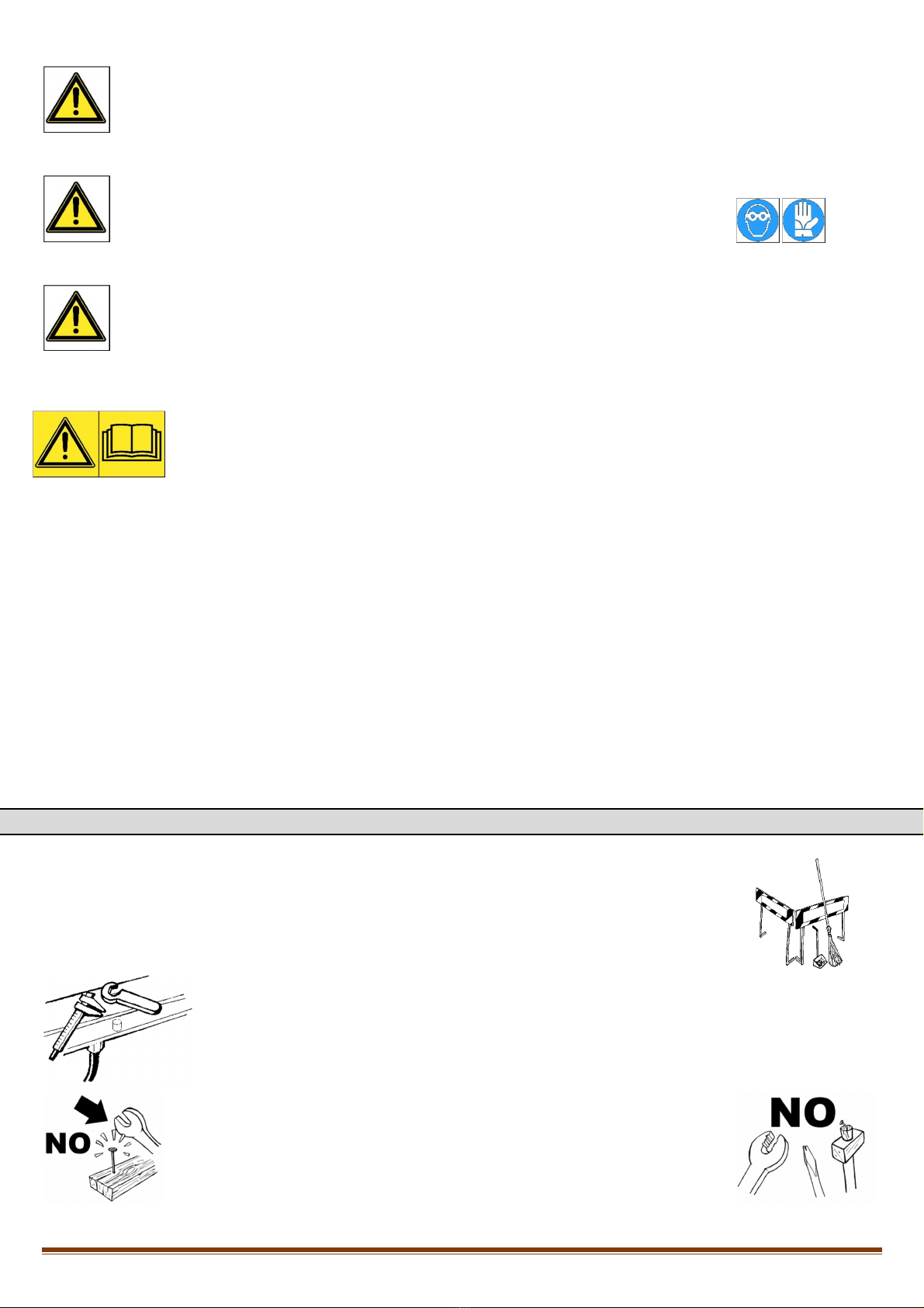
The working place must be kept clean and in orderly conditions. In particular, hazardous areas must be duly demarcated.
The working area around the machine and of any load devices must be free of obstacles.
Working tools and materials must not be left on the machine (or in places where they can interfere with mechanical
movements) and must not be left in places where they can fall and cause damage to people and / or things..
The used tools must be in good condition because any deteriorated tool, or in any case
under not optimal conditions, is a potential cause of danger.
Wizard Up30 M Rev. 0 01/02/2018
Pag. 5
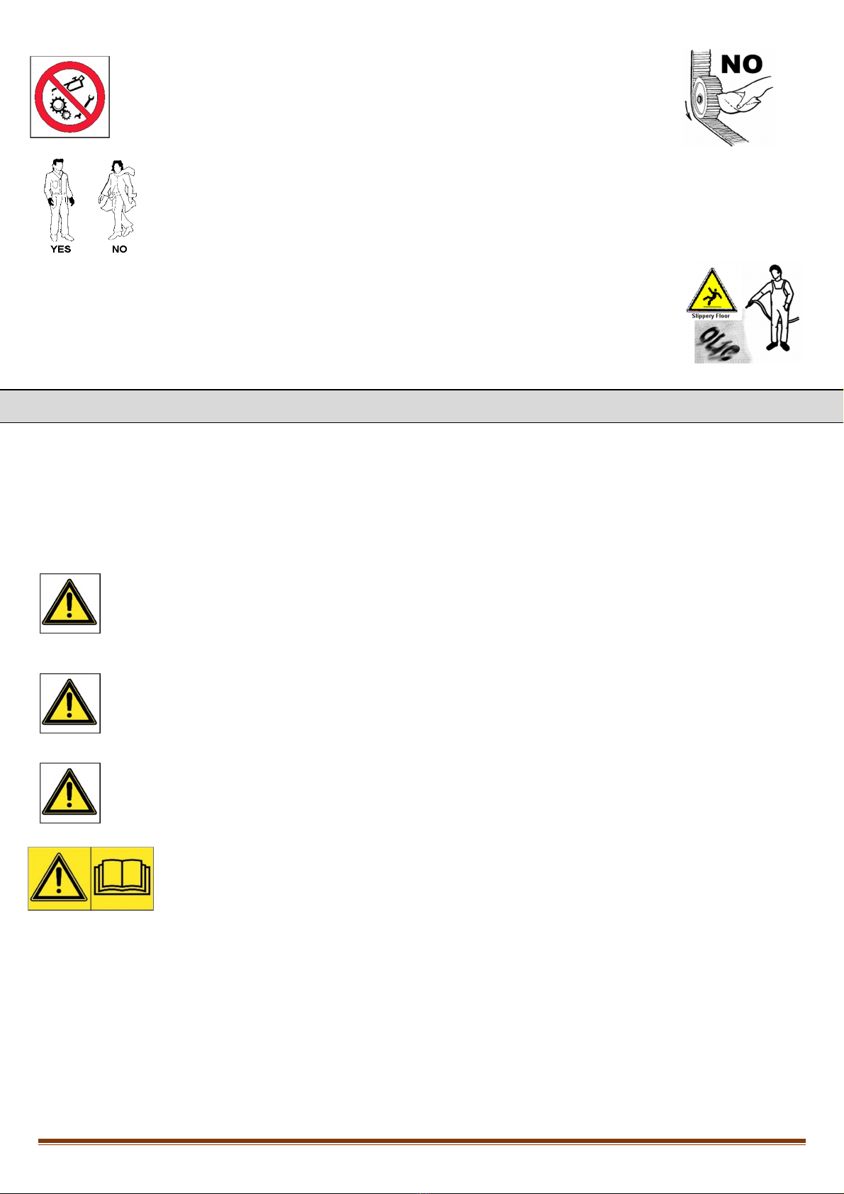
Do not clean or touch any moving mechanical parts.
The use of non-adherent clothing (eg scarves, ties, etc.) can be dangerous. Always use tight clothing.
Immediately remove oil / grease from the working area to prevent the risk of slipping / tripping.
3 – WIZARD UP30M LIFT DESCRIPTION
This machine is a mid-raise lift for vehicles, double platform and single scissor, designed to lift light vehicles in order to allow repair. ‘M’
version points out the possibility to move the lift in any part of the workshop.
The lift has been designed for exclusive use indoors and it has not been foreseen that it can be used to lift people.
The lift consists of 2 platforms mechanically independent operated by a pair of hydraulic cylinders. The synchronization of the platforms is
guaranteed by the presence of two torsion bars that rigidly connects scissors.
The lift has a capacity of 3000 kg.
CAUTION
The use of oil at a higher pressure than the maximum recommended could compromise the safe use of the
machine. Always check that the oil supply pressure does not exceed the recommended value.
CAUTION
The use of the machine it is not intended in places where the temperature is lower than -10 ° C, as it may
cause the reduction of lowering/lifting speed.
Do not exceed the maximum capacity of the lift.
CAUTION
It is not allowed any use other than that for which the machine was designed.
The execution of work not foreseen in the design phase could jeopardize the correct functioning of the
machine, generating unforeseeable risk.

Wizard Up30 M Rev. 0 01/02/2018
Pag. 6
3.1 – TECHNICAL FEATURES
Wizard UP30M lifts are composed as below:
1 P1 PLATFORM
2 P2 PLATFORM
3 RISING RAMPS
4 INTERNAL SCISSOR
5 EXTERNAL SCISSOR
6 HYDRAULIC CYLINDERS
7 CONTROL UNIT
8 TORSION BAR
9 WHEELS
10 BASE
SCISSORS - PLATFORMS:
The lift arms are made from 80x20 steel profiles, while the platform is formed by a shaped steel sheet with
reinforcement uprights and connected to the arms with steel pins in fixed points and with sliding blocks in moving points. All the
articulations of the lifting system have maintenance-free self-lubricating bushings.
CONTROL UNIT: It consists of a metal box containing the oil tank and the pump-motor unit, the solenoid valve group and the connections
for the electric and hydraulic power supplies. The controls are housed on the console, all operate under 24 V voltage and are of the "man
present" type. The commands are shown in the following pictures:

Wizard Up30 M Rev. 0 01/02/2018
Pag. 7
1. Master switch: The switch can be padlocked to prevent the use of the lift during the maintenance.
2. Beeper: signals with a high pitch the descent of the lift above the safety height.
3. Led: indicates the operation of the lift.
4. Lowering button: pushing it, the solenoid valves that actuate the lowering of the lift gets activated.
5. Lifting button: pushing it, the mechanisms actuating the lifting are activated.
6. Limit switch exclusion button: pressing it excludes the electric limit switch.
Wizard UP30M are suitable for lifting all types of cars and vans with a weight not exceeding 3000 kg.
The vehicle is gripped on the chassis by 4 rubber pads (supplied), leaving the wheels of the vehicle free.
1 2
3
4 5
6
Wizard Up30 M Rev. 0 01/02/2018
Pag. 8
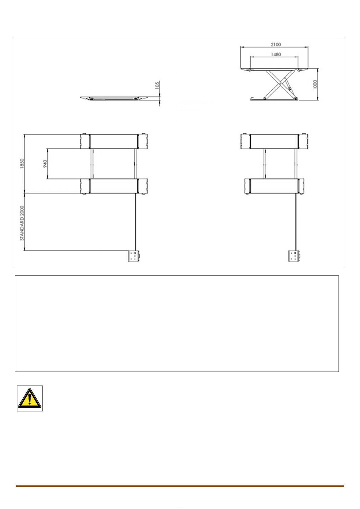
OVERALL DIMENSIONS:
TECHNICAL DATA
•Operation
•Capacity
•Weight
•Lifting time
•Lowering time
•Motor
•Noise level
•Working temperature
•Working Max. pressure
•Power
: Electro-hydraulic.
: 3000 Kg
: 450 Kg
: 20 sec.
: 25 sec.
: 3ph 230 - 400V 2.2 kW 50/60Hz
: < 70dB(A)
: -10° / +50°
: 260 bar
: 5,3 A
CHARACTERISTICS
•Low voltage controls (24V).
•Mechanical synchronism with two torsion
bars.
•Hydraulic system equipped with safety
mechanism in case of failure sue to broken
or cut tubes.
•Hand lowering device in case of power
failure.
•Acousting signal in lowering phase.
CAUTION
Dimensions and characteristics of the Wizard UP30M may change without notice.
Wizard Up30 M Rev. 0 01/02/2018
Pag. 9
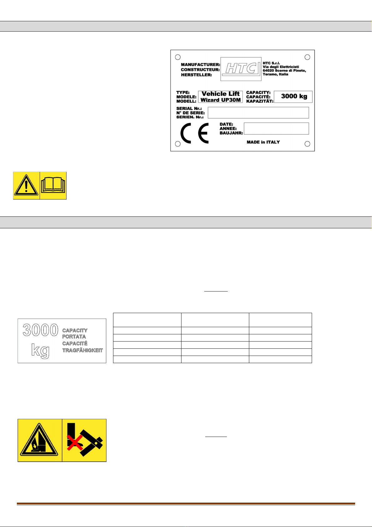
3.2 – CE PLATE
Following information are marked on the plate attached to the machine:
-Name and address of the manufacturer
-Machine model
-Max capacity of the lift
-Serial number
-CE and manufacturing date
Data shown on the identification plate must always be mentioned for assistance and spare parts.
3.3 – SAFETY PICTOGRAMS
It is very important to read this chapter carefully as it contains essential information on the risks that the operator and maintenance technician could take
in case of incorrect or improper use of the lifter. They are required to comply with the provisions contained in the laws and accident prevention
regulations in force in the country in which the lift is installed.
Lift capacity
CAUTION!
In first cm of vertical stroke the lift is manufacture to support a re uce capacity as
from the following scheme:
Platform height from
groun [mm] Stroke [mm] Max. capacity [kg]
105 0 1000
115 10 1150
160 55 1800
205 100 2450
250 145 3000
The lift is esigne to be loa e with full loa only when the platform height from
groun is min. 250mm. Do not overloa the structure for any reason by excee ing the
maximum recommen e loa .
The maximum capacity is to be un erstoo as the maximum overall weight that can be
lifte an oes not refer to the vehicle's empty weight only.
Danger crushing feet
DANGER!
Always check that there is sufficient space aroun the raise vehicle to ensure correct use
of the lift, paying particular attention to the imensions of the vehicle an referring to
any applicable regulations regar ing safety at work.
Wizard Up30 M Rev. 0 01/02/2018
Pag. 10
Danger crushing hands
DANGER!
In or er to prevent risks to thir parties an / or amage to property, before performing
any operation the user must make sure that there are no things or people close to the lift.
Prohibition to lift people
DANGER!
It is absolutely forbi en to lift people with this machine. Do not climb on the car or on
platforms when the loa is lifte .
CAUTION!
The machine must not be put into service until the user has rea an un erstoo all the
contents of this manual.
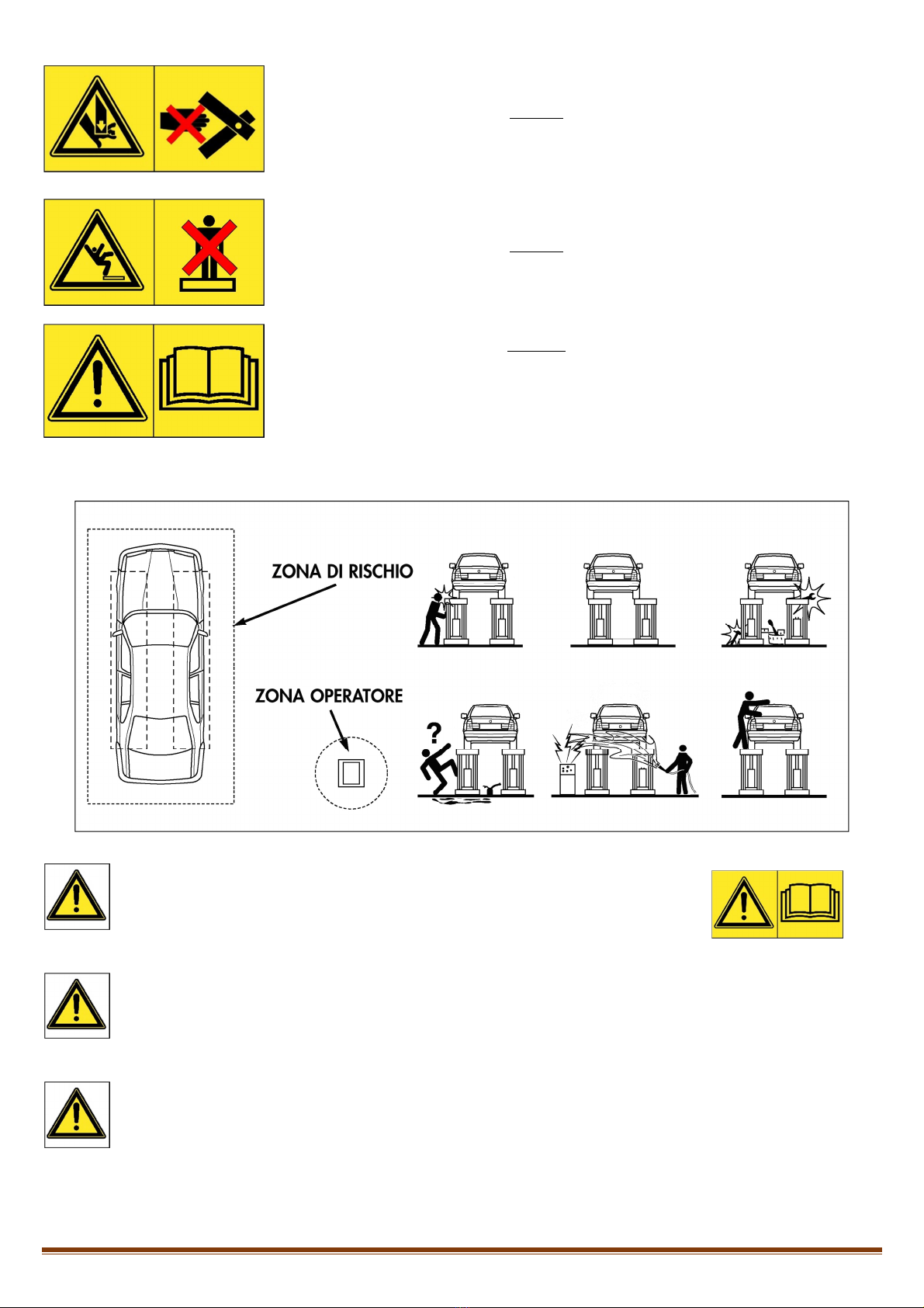
The safety pictograms are shown in the following figures.
DANGER
The machine must not be put into service until the user has read and understood all the
contents of this manual.
Using a padlock, to be applied to the main supply valve, it is possible to prevent the use of
the machine by unauthorized personnel.
DANGER
It is important that during the lifting or lowering of the lift, the operator only acts in the control area reserved to him
as shown in the figure above.
DANGER
It is forbidden for anyone to stop or transit within the risk area while the lift is operated and in any case when the
vehicle is already lifted.

Wizard Up30 M Rev. 0 01/02/2018
Pag. 11
DANGER
Do not use the machine without the protections or while they are deactivated or tampered.
DANGER
To lift the vehicle, use the rubber pads available respecting the correct support points recommended by the vehicle
manufacturer.
DANGER
After positioning the vehicle on the lift, stop the engine and insert the parking brake, remember to disengage the
gear lever and place it in the neutral gear.
DANGER
To avoid the risk of falling of the vehicle, ensure its correct positioning.
DANGER
It is forbidden to get on the vehicle and / or start it with the lifter lifted.
DANGER
It is forbidden to leave objects under the vehicle when lowering the lift.
DANGER
Keep the area near the lift clean by cleaning the oil stains to avoid dangerous slipping.
DANGER
It is forbidden to use jets of water, steam, paints and solvents in the areas near the lift and the control unit.
DANGER
Presence and "climbing" of people on platforms or under platforms both during lifting and when the vehicle is lifted
is strictly forbidden.
DANGER
It is forbidden any different use of the lift other than that for which it was designed, non-compliance with this rule
can cause serious accidents to people and things

Wizard Up30 M Rev. 0 01/02/2018
Pag. 12
DANGER
In case of abnormal action of the lift, stop it and switch off the on / off selector by locking it with a padlock.
Restoring operation must be done by expert personnel. Before repair and maintenance of the lift make sure that the
power supply is disconnected from the main power supply.
DANGER
Each operator must take vision and be able to recognize the meanings of the symbols shown.
The adhesive
signals must not be detached, tampered or destroyed. The owner of the machine is obliged to provide for their
replacement, if they are damaged or illegible.
DANGER
Load and unload the machine with the utmost care, making sure that there are no persons
or objects in the range of the lifting device during handling.
3.4 –CONDITIONS OF THE WORKING AREA
The machine has been designed exclusively for indoor area use. Therefore it is not allowed to use it outdoors.
Room temperature: 10÷35 °C
Humidity of the air, %, max: 80
CAUTION
Check that there is enough space around the machine to guarantee correct use according to the size of the vehicle
to be repaired and in compliance with the safety regulations in force.
DANGER
Avoid working in low light conditions.
4 – INSTALLATION AND OPERATION OF THE LIFT
The following chapter will list the criteria and conditions necessary for the Wizard UP30 M to be assembled correctly and then put into service in safe
conditions.
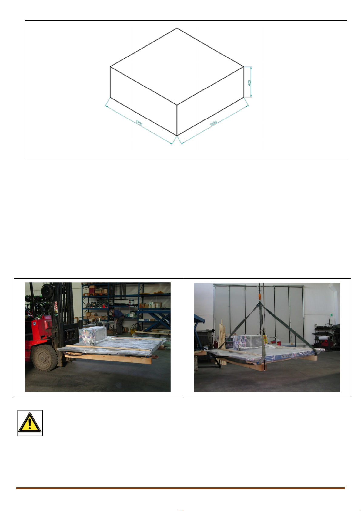
4.1 – RECEIPT AND PACKAGING HANDLING
The lift in standard version is shipped already assembled. The packaging configuration is shown in the following figure:
Wizard Up30 M Rev. 0 01/02/2018
Pag. 13
•N°2 basis and platforms (P1-P2), including wooden pallet, wood spacers, packed with bubble wrap and metal strips.
•N°1 power unit packed with bubble wrap and metal strips.
•N°1 cardboard box with electric and hydraulic kit connections, rubber pads and user manual.
•N°1 set of rising/lowering ramps.
During handling of the package, use a lifting device with a capacity suitable for the weight to be moved and / or lifted.
The package can be lifted or moved with forklifts or cranes. The movement must be assisted by an operator in order to avoid dangerous fluctuations in
the load.
At the arrival, check that the goods have no damages and that all the parts written on the packing list are there.
Inform immediately the person in charge or the forwarder in case any part is missing or of any damages incurred during transport; in the moment of
loading/unloading respect the gripping point of the package as shown on the below picture (use wooden spacers when using bands to avoid crushing
cardboard boxes).
DANGER
Load, unload and handle the machine with the maximum care, making sure that there are no people or obstacles in
the range of the lifting device during handling.
Wizard Up30 M Rev. 0 01/02/2018
Pag. 14
4.2 – STORAGE
If the machine needs temporary storage, keep it in a dry place away from bad weather before it is unpacked..
DANGER
Do not stack the packages.
4.3 – UNPACKING
The machine must be mounted on a horizontal plane free of any obstacle, having verified that there is sufficient space around it to guarantee its
correct use. After positioning the machine near the place chosen for installation, lift the packaging using the forklift and remove the bubble wrap.
The wooden packaging and the bubble wrap can be recycled.
DANGER
All residual material must be disposed according to the regulations in force concerning waste disposal.
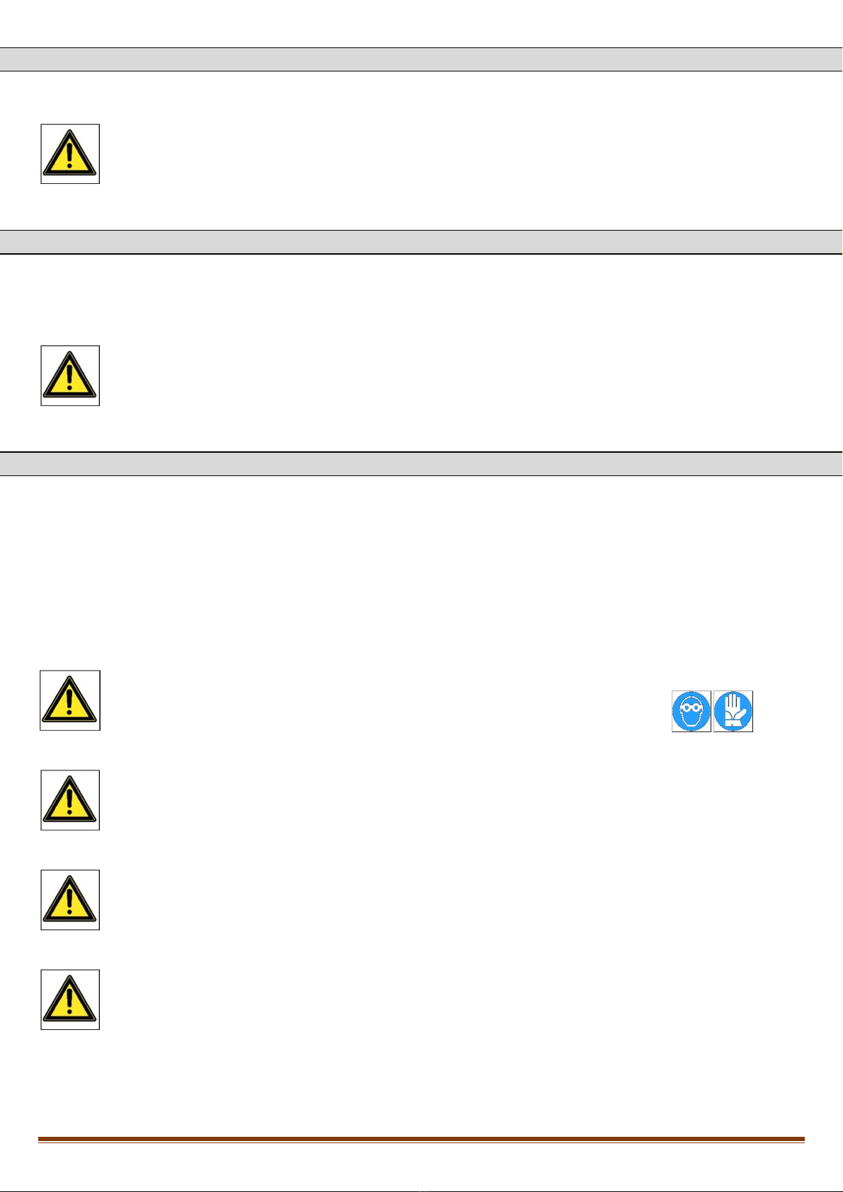
4.4 – MACHINE INSTALLATION
To guarantee correct assembly and safe use of the machine, the machine is delivered pre-assembled.
The machine must be installed respecting the safety distances from walls, columns, other machines and other devices present in the working area in
particular, the height of the local must be at least 4500 mm and the distance from walls must be at least 1500mm.
Ground specifics:
DANGER
Proceed with the installation and assembly of the machine only after wearing protective
equipment (gloves / goggles / protective shield).
DANGER
Before proceeding with the assembly and installation of the machine, check that the flooring is of a suitable type to
support the loads deriving from the use of the machine.
DANGER
The lift must be installed exclusively indoor.
DANGER
It is forbidden to use the lift in an explosive or flammable atmosphere.
Concrete resistance class ≥ 250 kgf/cm
2
concrete thickness ≥ 140 mm
Planarity ± 1mm
Wizard Up30 M Rev. 0 01/02/2018
Pag. 15
DANGER
The installation of the lift is responsibility of specialized technicians, appointed by the manufacturer or by
authorized dealers. Lack of compliance with this rule could cause serious damage to people and things and in any
case relieves the manufacturer from any responsibility.
The personnel assigned to assemble the machine must be qualified, competent and be aware of all the regulations in force concerning prevention of
accidents.
INSTALLATION PROCEDURE
1. Positioning of the lift
2. Check availability of power supply
3. Hydraulic connection
4. Electrical connection
5. Concrete base and/or lift fixing
6. First start-up
Position the lift with a crane or any other suitable lifting device at the desired point. To open the lift, lift with a crane the platforms at a height of approx.
50 cm, put a wooden spacer between the scissors in the way to avoid closure. Proceed with the elimination of small unevenness of the ground using
metal shims. Proceed to the harness to move the lift again.
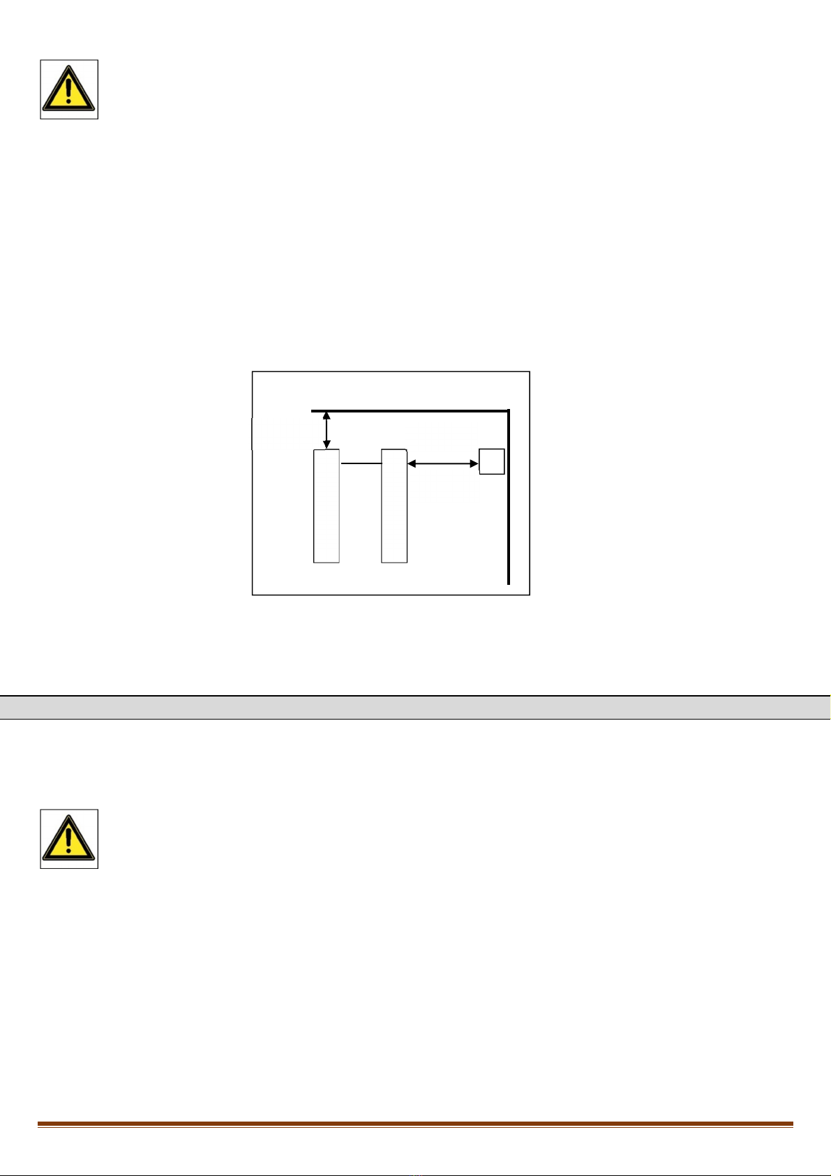
4.5 – HYDRAULIC PLANT CONNECTION
Cylinders of the Wizard UP30 M are feeded by an hydraulic pump. Before starting the machine, it is necessary to connect the pipe coming from the
pump to the pipes of the cylinders using the supplied hydraulic fittings.
DANGER
Do not change for any reason the adjustment of the max pressure valve.
The mechanical components have not been sized to work at a higher pressure than the one set in the factory.
Alteration of the maximum working pressure of the control unit invalidates immediately the guarantee of the lift.
P1
P2
Min.
1500 mm
Max
2000 mm
Min
800 mm
Local height
≥
4500 mm
Wizard Up30 M Rev. 0 01/02/2018
Pag. 16
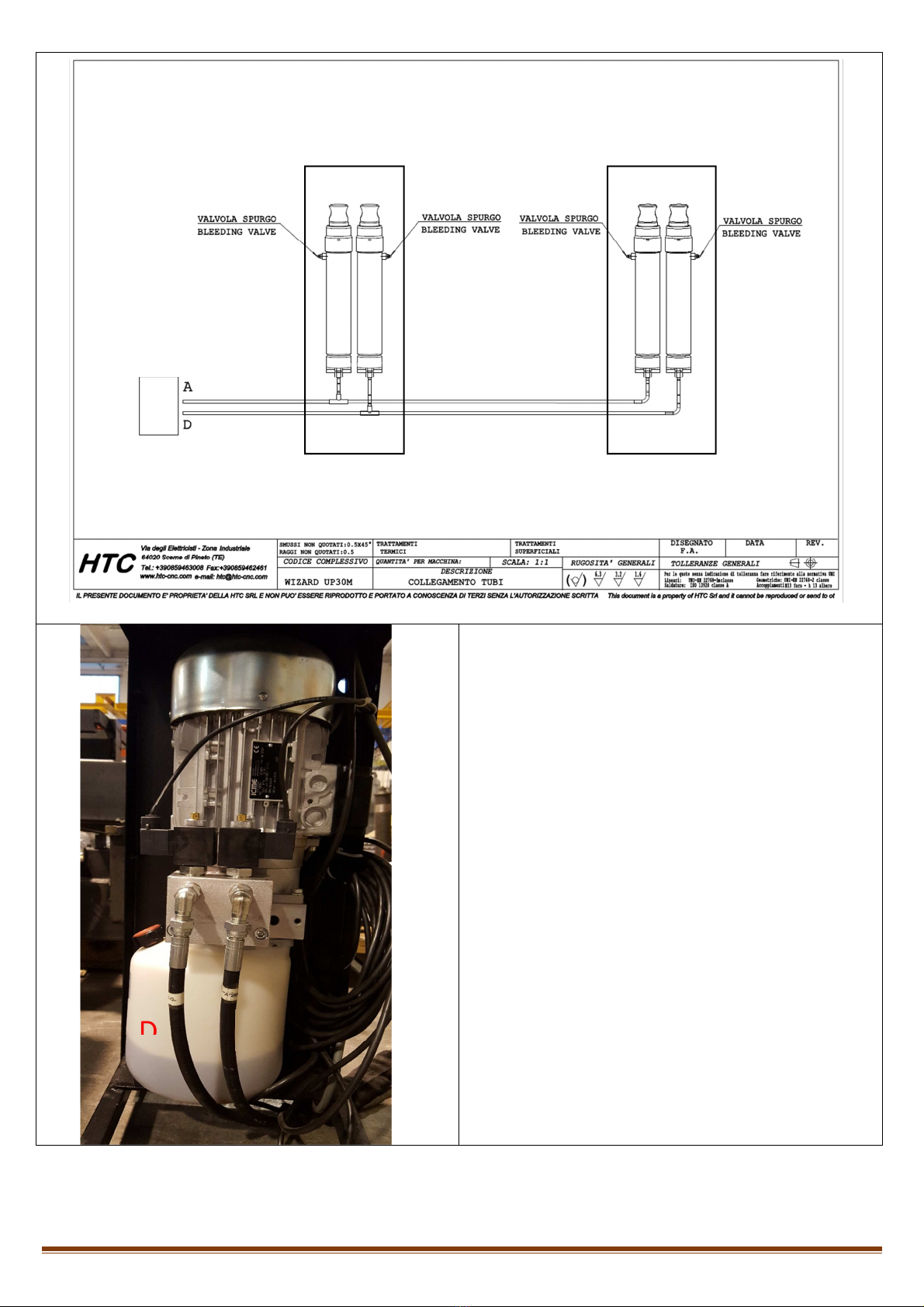
The hydraulic block is constituted as below:
A– Flow / return cylinder A1 of hydraulic scheme;
D– Flow / return cylinder B1 of hydraulic scheme;
EV1-EV2 – Electro valve;
Hydraulic connection procedure:
Connect hydraulic hose A(above figure) in the flow of
hydraulic block A(side figure); hydraulic hose D(above
figure) in the flow of hydraulic block D.
P1
P2
A
D
EV2
EV1
E
V
2

Wizard Up30 M Rev. 0 01/02/2018
Pag. 17
Pos. Description
1 Suction filter
2 4,2 cc pump
3 Max pressure valve 260 bar
4 Flow regulation STF 5L
5 Unidirectional valve
6 Electro valve CE1-NC-EM
7 Bleeding oil recovery
8 2,2 kW Motor
9 Parachute valve ¼”

Wizard Up30 M Rev. 0 01/02/2018
Pag. 18
4.6 – ELECTRIC PLANT CONNECTION
The installer must check for an electrical connection in compliance with current regulations, including a general switch and an adequate
magnetothermal protection
CAUTION
All operations for connection to the electrical network must be carried out by qualified personnel.
CAUTION
Verify that the supply voltage is compliant.
CAUTION
Check the correct connection of the supply phases. An incorrect electrical connection could cause damages to the
motor that will not be covered by the manufacturer's warranty
CAUTION
The power connection to the control unit takes place by opening the control unit cover and connecting, through
terminals, the power supply cable to the main switch cable, by passing it through the appropriate space located on
the back of the control unit. Make sure that the power supply line is adequately protected by a magnetothermic
switch with adequate capacities and characteristics and compliant with current safety regulations.
CAUTION
Before acting inside the control unit, for connection to power or for repairing a fault in the electrical devices, make
sure that the main power supply is disconnected, thus avoiding the dangerous possibility of electric shock.
CAUTION
Do not operate the hydraulic unit before filling the oil tank. Using the control unit without oil could damage the
pump.
CAUTION
Always prevent the hydraulic unit from coming into contact with water or other liquids.

Wizard Up30 M Rev. 0 01/02/2018
Pag. 19

Wizard Up30 M Rev. 0 01/02/2018
Pag. 20
Table of contents
Popular Lifting System manuals by other brands


EZ-ACCESS
EZ-ACCESS SUITCASE Singlefold Ramp instructions

Skytrak
Skytrak 6036 Service manual

AAQ
AAQ AL-6254A Installation manual & operation instructions

Dhollandia
Dhollandia DH-LSP installation manual

Peri
Peri UP Flex Staircase 100 with Deck UDG Instructions for Assembly and Dismantling

TLS
TLS TLS430FDCEx1 Series Installation, operation & service parts manual


