Skytrak 6036 User manual

An Oshkosh Corporation Company
Service Manual
Models
6036, 6042, 8042,
10042 & 10054
SN 0160069719 to Present
including 0160065791, 0160065792, 0160065796,
0160065798, 0160065824, 0160065825,
0160065826, 0160069336, 0160069359,
0160069383, 0160069411, 0160069441,
0160069566, 0160069567 & 0160069568
31211015
Revised
July 31, 2017


EFFECTIVITY PAGE
6036, 6042, 8042, 10042, 10054 31211015 i
DATE REVISION DESCRIPTION
August 12, 2015 A Original Issue Of Manual
October 21, 2015 B Revise pages ii, 2-15, 2-17, 2-18, 2-20 thru 2-23, 3-49, 5-18, 7-12, 7-13, Revise pages
8-6 thru 8-29, 9-4, 9-5, Add pages 9-9, 9-13, 9-14, 9-23, 9-24, 9-27, 9-29, 9-30, Revise
page 9-31, Add pages 9-32 thru 34, 10-5, 10-7, 10-15, 10-17, 10-18.
January 04, 2017 C Revised pages 2-4 thru 2-78, 4-5, 4-8 thru 4-12, 7-8 thru 7-11, 8-6 thru 8-37, 8-43, 8-44,
9-4 thru 9-18, 9-20, 9-35 thru 9-94, 10-7
July 31, 2017 D Revised page 2-12, pages 7-9 thru 7-16, 9-43 thru 9-45
READ THIS FIRST
31211015 6036, 6042, 8042, 10042, 10054
ii
Modifications
Modifications to this machine may affect compliance with Industry Standards and/or Governmental Regulations. Any
modification must be approved by JLG.
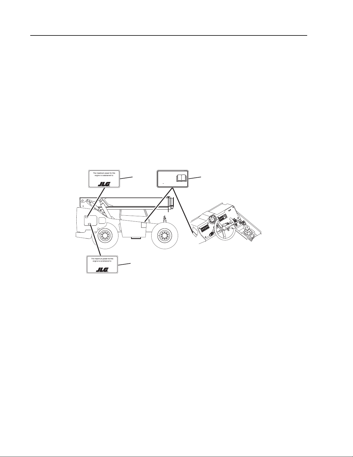
Machine Configuration
Two configurations of each machine are included in this manual. Determine if machine is equipped with Ultra Low Sulfur Fuel
Decal (1) as indicated below.
• If equipped with the Ultra Low Sulfur decal, all specific references to this machine configuration will be referred to as
Ultra Low Sulfur (ULS)from this point forward.
•Ifnot equipped with the Ultra Low Sulfur decal, all specific references to this machine configuration will be referred to as
Low Sulfur (LS) from this point forward.
Maximum engine power can be found on the decals (2) located on the inside of the side engine compartment doors.
O 5603H
ULTRA LOW
SULFUR DIESEL
FUEL ONLY
S < 15 mg/kg
1001125387 A
XXXhp (XXkW) @ XXXX RPM
XXXXXXXXXX_A
2 1
XXXhp (XXkW) @ XXXX RPM
XXXXXXXXXX_A
(8042, 10042, 10054)
(6036, 6042)
2

SECTION CONTENTS
Section Subject Page
i
6036, 6042, 8042, 10042, 10054 31211015
Section 1
Safety Practices . . . . . . . . . . . . . . . . . . . . . . . . . . . . . . . . . . . . . . . . . . . . . . . . . . . . . . . . . . . . . . . . . . . . 1-1
1.1 Introduction. . . . . . . . . . . . . . . . . . . . . . . . . . . . . . . . . . . . . . . . . . . . . . . . . . . . . . . . . . . . . . . . . . . . . . . . . . . . . . 1-2
1.2 Disclaimer. . . . . . . . . . . . . . . . . . . . . . . . . . . . . . . . . . . . . . . . . . . . . . . . . . . . . . . . . . . . . . . . . . . . . . . . . . . . . . . . 1-2
1.3 Operation & Safety Manual . . . . . . . . . . . . . . . . . . . . . . . . . . . . . . . . . . . . . . . . . . . . . . . . . . . . . . . . . . . . . . . 1-2
1.4 Do Not Operate Tags . . . . . . . . . . . . . . . . . . . . . . . . . . . . . . . . . . . . . . . . . . . . . . . . . . . . . . . . . . . . . . . . . . . . . 1-2
1.5 Safety Information. . . . . . . . . . . . . . . . . . . . . . . . . . . . . . . . . . . . . . . . . . . . . . . . . . . . . . . . . . . . . . . . . . . . . . . . 1-2
1.6 Safety Instructions. . . . . . . . . . . . . . . . . . . . . . . . . . . . . . . . . . . . . . . . . . . . . . . . . . . . . . . . . . . . . . . . . . . . . . . . 1-3
1.7 Safety Decals . . . . . . . . . . . . . . . . . . . . . . . . . . . . . . . . . . . . . . . . . . . . . . . . . . . . . . . . . . . . . . . . . . . . . . . . . . . . . 1-4
Section 2
General Information and Specifications . . . . . . . . . . . . . . . . . . . . . . . . . . . . . . . . . . . . . . . . . . . . . . 2-1
2.1 Replacement Parts and Warranty Information . . . . . . . . . . . . . . . . . . . . . . . . . . . . . . . . . . . . . . . . . . . . . 2-3
2.2 Specifications . . . . . . . . . . . . . . . . . . . . . . . . . . . . . . . . . . . . . . . . . . . . . . . . . . . . . . . . . . . . . . . . . . . . . . . . . . . . 2-4
2.3 Fluid Specifications . . . . . . . . . . . . . . . . . . . . . . . . . . . . . . . . . . . . . . . . . . . . . . . . . . . . . . . . . . . . . . . . . . . . . . . 2-7
2.4 Fluid and Lubricant Capacities . . . . . . . . . . . . . . . . . . . . . . . . . . . . . . . . . . . . . . . . . . . . . . . . . . . . . . . . . . . . 2-9
2.5 Service and Maintenance Schedules . . . . . . . . . . . . . . . . . . . . . . . . . . . . . . . . . . . . . . . . . . . . . . . . . . . . . . 2-10
2.6 Lubrication Schedules . . . . . . . . . . . . . . . . . . . . . . . . . . . . . . . . . . . . . . . . . . . . . . . . . . . . . . . . . . . . . . . . . . . . 2-14
2.7 Thread Locking Compound . . . . . . . . . . . . . . . . . . . . . . . . . . . . . . . . . . . . . . . . . . . . . . . . . . . . . . . . . . . . . . . 2-20
2.8 Torque Charts . . . . . . . . . . . . . . . . . . . . . . . . . . . . . . . . . . . . . . . . . . . . . . . . . . . . . . . . . . . . . . . . . . . . . . . . . . . . 2-21
2.9 Hydraulic Connection Assembly and Torque Specification . . . . . . . . . . . . . . . . . . . . . . . . . . . . . . . . . 2-31
Section 3
Boom . . . . . . . . . . . . . . . . . . . . . . . . . . . . . . . . . . . . . . . . . . . . . . . . . . . . . . . . . . . . . . . . . . . . . . . 3-1
3.1 Boom System Component Terminology . . . . . . . . . . . . . . . . . . . . . . . . . . . . . . . . . . . . . . . . . . . . . . . . . . . 3-3
3.2 Safety Information. . . . . . . . . . . . . . . . . . . . . . . . . . . . . . . . . . . . . . . . . . . . . . . . . . . . . . . . . . . . . . . . . . . . . . . . 3-4
3.3 Boom System - Three Section (6036, 6042, 8042 & 10042) . . . . . . . . . . . . . . . . . . . . . . . . . . . . . . . . . . 3-4
3.4 Boom Assembly Maintenance. . . . . . . . . . . . . . . . . . . . . . . . . . . . . . . . . . . . . . . . . . . . . . . . . . . . . . . . . . . . . 3-4
3.5 Boom System - Four Section (10054) . . . . . . . . . . . . . . . . . . . . . . . . . . . . . . . . . . . . . . . . . . . . . . . . . . . . . . 3-15
3.6 Boom Assembly Maintenance. . . . . . . . . . . . . . . . . . . . . . . . . . . . . . . . . . . . . . . . . . . . . . . . . . . . . . . . . . . . . 3-15
3.7 Boom Extend and Retract Chains. . . . . . . . . . . . . . . . . . . . . . . . . . . . . . . . . . . . . . . . . . . . . . . . . . . . . . . . . . 3-28
3.8 Boom Wear Pads . . . . . . . . . . . . . . . . . . . . . . . . . . . . . . . . . . . . . . . . . . . . . . . . . . . . . . . . . . . . . . . . . . . . . . . . . 3-48
3.9 Quick Coupler . . . . . . . . . . . . . . . . . . . . . . . . . . . . . . . . . . . . . . . . . . . . . . . . . . . . . . . . . . . . . . . . . . . . . . . . . . . . 3-49
3.10 Forks . . . . . . . . . . . . . . . . . . . . . . . . . . . . . . . . . . . . . . . . . . . . . . . . . . . . . . . . . . . . . . . . . . . . . . . . . . . . . . . . . . . . . 3-49
3.11 Troubleshooting. . . . . . . . . . . . . . . . . . . . . . . . . . . . . . . . . . . . . . . . . . . . . . . . . . . . . . . . . . . . . . . . . . . . . . . . . . 3-50
Section 4
Cab and Covers . . . . . . . . . . . . . . . . . . . . . . . . . . . . . . . . . . . . . . . . . . . . . . . . . . . . . . . . . . . . . . . . . . . . . 4-1
4.1 Operator Cab and Covers Component Terminology. . . . . . . . . . . . . . . . . . . . . . . . . . . . . . . . . . . . . . . . 4-2
4.2 Operator Cab. . . . . . . . . . . . . . . . . . . . . . . . . . . . . . . . . . . . . . . . . . . . . . . . . . . . . . . . . . . . . . . . . . . . . . . . . . . . . 4-3
4.3 Cab Components. . . . . . . . . . . . . . . . . . . . . . . . . . . . . . . . . . . . . . . . . . . . . . . . . . . . . . . . . . . . . . . . . . . . . . . . . 4-3
4.4 Cab Removal . . . . . . . . . . . . . . . . . . . . . . . . . . . . . . . . . . . . . . . . . . . . . . . . . . . . . . . . . . . . . . . . . . . . . . . . . . . . . 4-13
4.5 Cab Installation. . . . . . . . . . . . . . . . . . . . . . . . . . . . . . . . . . . . . . . . . . . . . . . . . . . . . . . . . . . . . . . . . . . . . . . . . . . 4-14

Section Subject Page
ii 31211015 6036, 6042, 8042, 10042, 10054
Section 5
Axles, Drive Shafts, Wheels and Tires . . . . . . . . . . . . . . . . . . . . . . . . . . . . . . . . . . . . . . . . . . . . . . . . 5-1
5.1 Axle, Drive Shaft and Wheel Component Terminology. . . . . . . . . . . . . . . . . . . . . . . . . . . . . . . . . . . . . 5-2
5.2 General Information . . . . . . . . . . . . . . . . . . . . . . . . . . . . . . . . . . . . . . . . . . . . . . . . . . . . . . . . . . . . . . . . . . . . . 5-5
5.3 Axle Assemblies . . . . . . . . . . . . . . . . . . . . . . . . . . . . . . . . . . . . . . . . . . . . . . . . . . . . . . . . . . . . . . . . . . . . . . . . . 5-5
5.4 Axle Assembly and Drive Shaft Troubleshooting . . . . . . . . . . . . . . . . . . . . . . . . . . . . . . . . . . . . . . . . . . 5-12
5.5 Drive Shafts. . . . . . . . . . . . . . . . . . . . . . . . . . . . . . . . . . . . . . . . . . . . . . . . . . . . . . . . . . . . . . . . . . . . . . . . . . . . . . 5-16
5.6 Wheels and Tires . . . . . . . . . . . . . . . . . . . . . . . . . . . . . . . . . . . . . . . . . . . . . . . . . . . . . . . . . . . . . . . . . . . . . . . . . 5-17
5.7 Brakes . . . . . . . . . . . . . . . . . . . . . . . . . . . . . . . . . . . . . . . . . . . . . . . . . . . . . . . . . . . . . . . . . . . . . . . . . . . . . . . . . . . 5-18
5.8 Towing a Disabled Machine . . . . . . . . . . . . . . . . . . . . . . . . . . . . . . . . . . . . . . . . . . . . . . . . . . . . . . . . . . . . . . 5-19
Section 6
Transmission . . . . . . . . . . . . . . . . . . . . . . . . . . . . . . . . . . . . . . . . . . . . . . . . . . . . . . . . . . . . . . . . . . . . . . . 6-1
6.1 Transmission Assembly Component Terminology . . . . . . . . . . . . . . . . . . . . . . . . . . . . . . . . . . . . . . . . . 6-2
6.2 Transmission Serial Number . . . . . . . . . . . . . . . . . . . . . . . . . . . . . . . . . . . . . . . . . . . . . . . . . . . . . . . . . . . . . . 6-3
6.3 Transmission Specifications and Maintenance Information . . . . . . . . . . . . . . . . . . . . . . . . . . . . . . . . 6-3
6.4 Transmission Replacement . . . . . . . . . . . . . . . . . . . . . . . . . . . . . . . . . . . . . . . . . . . . . . . . . . . . . . . . . . . . . . . 6-3
6.5 Transmission Troubleshooting. . . . . . . . . . . . . . . . . . . . . . . . . . . . . . . . . . . . . . . . . . . . . . . . . . . . . . . . . . . . 6-7
Section 7
Engine . . . . . . . . . . . . . . . . . . . . . . . . . . . . . . . . . . . . . . . . . . . . . . . . . . . . . . . . . . . . . . . . . . . . . . . 7-1
7.1 Introduction . . . . . . . . . . . . . . . . . . . . . . . . . . . . . . . . . . . . . . . . . . . . . . . . . . . . . . . . . . . . . . . . . . . . . . . . . . . . . 7-3
7.2 Engine Serial Number . . . . . . . . . . . . . . . . . . . . . . . . . . . . . . . . . . . . . . . . . . . . . . . . . . . . . . . . . . . . . . . . . . . . 7-3
7.3 Specifications and Maintenance Information. . . . . . . . . . . . . . . . . . . . . . . . . . . . . . . . . . . . . . . . . . . . . . 7-3
7.4 Engine Cooling System. . . . . . . . . . . . . . . . . . . . . . . . . . . . . . . . . . . . . . . . . . . . . . . . . . . . . . . . . . . . . . . . . . . 7-5
7.5 Engine Electrical System . . . . . . . . . . . . . . . . . . . . . . . . . . . . . . . . . . . . . . . . . . . . . . . . . . . . . . . . . . . . . . . . . 7-6
7.6 Fuel System. . . . . . . . . . . . . . . . . . . . . . . . . . . . . . . . . . . . . . . . . . . . . . . . . . . . . . . . . . . . . . . . . . . . . . . . . . . . . . 7-7
7.7 Engine Exhaust System. . . . . . . . . . . . . . . . . . . . . . . . . . . . . . . . . . . . . . . . . . . . . . . . . . . . . . . . . . . . . . . . . . . 7-17
7.8 Air Cleaner Assembly . . . . . . . . . . . . . . . . . . . . . . . . . . . . . . . . . . . . . . . . . . . . . . . . . . . . . . . . . . . . . . . . . . . . 7-21
7.9 Engine Replacement . . . . . . . . . . . . . . . . . . . . . . . . . . . . . . . . . . . . . . . . . . . . . . . . . . . . . . . . . . . . . . . . . . . . . 7-22
7.10 Isolation Coupler. . . . . . . . . . . . . . . . . . . . . . . . . . . . . . . . . . . . . . . . . . . . . . . . . . . . . . . . . . . . . . . . . . . . . . . . . 7-24
Section 8 . . . . . . . . . . . . . . . . . . . . . . . . . . . . . . . . . . . . . . . . . . . . . . . . . . . . . . . . . . . . . . . . . . . . . . .
Hydraulic Section . . . . . . . . . . . . . . . . . . . . . . . . . . . . . . . . . . . . . . . . . . . . . . . . . . . . . . . . . . . . . . . . . . . 8-1
8.1 Hydraulic Component Terminology . . . . . . . . . . . . . . . . . . . . . . . . . . . . . . . . . . . . . . . . . . . . . . . . . . . . . . 8-2
8.2 Safety Information . . . . . . . . . . . . . . . . . . . . . . . . . . . . . . . . . . . . . . . . . . . . . . . . . . . . . . . . . . . . . . . . . . . . . . . 8-4
8.3 Specifications. . . . . . . . . . . . . . . . . . . . . . . . . . . . . . . . . . . . . . . . . . . . . . . . . . . . . . . . . . . . . . . . . . . . . . . . . . . . 8-4
8.4 Hydraulic Circuits . . . . . . . . . . . . . . . . . . . . . . . . . . . . . . . . . . . . . . . . . . . . . . . . . . . . . . . . . . . . . . . . . . . . . . . . 8-5
8.5 Hydraulic Pressure Diagnosis . . . . . . . . . . . . . . . . . . . . . . . . . . . . . . . . . . . . . . . . . . . . . . . . . . . . . . . . . . . . . 8-5
8.6 Hydraulic Reservoir . . . . . . . . . . . . . . . . . . . . . . . . . . . . . . . . . . . . . . . . . . . . . . . . . . . . . . . . . . . . . . . . . . . . . . 8-38
8.7 Hydraulic System Pump . . . . . . . . . . . . . . . . . . . . . . . . . . . . . . . . . . . . . . . . . . . . . . . . . . . . . . . . . . . . . . . . . . 8-39
8.8 Valves and Manifolds. . . . . . . . . . . . . . . . . . . . . . . . . . . . . . . . . . . . . . . . . . . . . . . . . . . . . . . . . . . . . . . . . . . . . 8-40
8.9 Hydraulic Cylinders . . . . . . . . . . . . . . . . . . . . . . . . . . . . . . . . . . . . . . . . . . . . . . . . . . . . . . . . . . . . . . . . . . . . . . 8-51

Section Subject Page
iii
6036, 6042, 8042, 10042, 10054 31211015
Section 9
Electrical System . . . . . . . . . . . . . . . . . . . . . . . . . . . . . . . . . . . . . . . . . . . . . . . . . . . . . . . . . . . . . . . . . . . 9-1
9.1 Electrical Component Terminology. . . . . . . . . . . . . . . . . . . . . . . . . . . . . . . . . . . . . . . . . . . . . . . . . . . . . . . . 9-3
9.2 Specifications . . . . . . . . . . . . . . . . . . . . . . . . . . . . . . . . . . . . . . . . . . . . . . . . . . . . . . . . . . . . . . . . . . . . . . . . . . . . 9-4
9.3 Safety Information. . . . . . . . . . . . . . . . . . . . . . . . . . . . . . . . . . . . . . . . . . . . . . . . . . . . . . . . . . . . . . . . . . . . . . . . 9-4
9.4 Fuses and Relays . . . . . . . . . . . . . . . . . . . . . . . . . . . . . . . . . . . . . . . . . . . . . . . . . . . . . . . . . . . . . . . . . . . . . . . . . 9-4
9.5 Electrical System Schematics. . . . . . . . . . . . . . . . . . . . . . . . . . . . . . . . . . . . . . . . . . . . . . . . . . . . . . . . . . . . . . 9-7
9.6 Dielectric Grease Application . . . . . . . . . . . . . . . . . . . . . . . . . . . . . . . . . . . . . . . . . . . . . . . . . . . . . . . . . . . . . 9-17
9.7 Engine Start Circuit . . . . . . . . . . . . . . . . . . . . . . . . . . . . . . . . . . . . . . . . . . . . . . . . . . . . . . . . . . . . . . . . . . . . . . . 9-20
9.8 Battery . . . . . . . . . . . . . . . . . . . . . . . . . . . . . . . . . . . . . . . . . . . . . . . . . . . . . . . . . . . . . . . . . . . . . . . . . . . . . . . . . . . 9-21
9.9 Charging Circuit . . . . . . . . . . . . . . . . . . . . . . . . . . . . . . . . . . . . . . . . . . . . . . . . . . . . . . . . . . . . . . . . . . . . . . . . . . 9-22
9.10 Window Wiper/Washer Windshield Wiper Motor. . . . . . . . . . . . . . . . . . . . . . . . . . . . . . . . . . . . . . . . . . . 9-23
9.11 Cab Heater and Fan. . . . . . . . . . . . . . . . . . . . . . . . . . . . . . . . . . . . . . . . . . . . . . . . . . . . . . . . . . . . . . . . . . . . . . . 9-26
9.12 Solenoids, Sensors and Senders . . . . . . . . . . . . . . . . . . . . . . . . . . . . . . . . . . . . . . . . . . . . . . . . . . . . . . . . . . . 9-27
9.13 Display Monitor . . . . . . . . . . . . . . . . . . . . . . . . . . . . . . . . . . . . . . . . . . . . . . . . . . . . . . . . . . . . . . . . . . . . . . . . . . 9-33
9.14 Dash Switches . . . . . . . . . . . . . . . . . . . . . . . . . . . . . . . . . . . . . . . . . . . . . . . . . . . . . . . . . . . . . . . . . . . . . . . . . . . . 9-33
9.15 Machine Data . . . . . . . . . . . . . . . . . . . . . . . . . . . . . . . . . . . . . . . . . . . . . . . . . . . . . . . . . . . . . . . . . . . . . . . . . . . . 9-36
9.16 Analyzer Software Accessibility . . . . . . . . . . . . . . . . . . . . . . . . . . . . . . . . . . . . . . . . . . . . . . . . . . . . . . . . . . . 9-39
9.17 Telematics Gateway . . . . . . . . . . . . . . . . . . . . . . . . . . . . . . . . . . . . . . . . . . . . . . . . . . . . . . . . . . . . . . . . . . . . . . 9-43
9.18 Troubleshooting. . . . . . . . . . . . . . . . . . . . . . . . . . . . . . . . . . . . . . . . . . . . . . . . . . . . . . . . . . . . . . . . . . . . . . . . . . 9-50
9.19 Machine Fault Codes . . . . . . . . . . . . . . . . . . . . . . . . . . . . . . . . . . . . . . . . . . . . . . . . . . . . . . . . . . . . . . . . . . . . . 9-51
9.20 Engine Fault Codes . . . . . . . . . . . . . . . . . . . . . . . . . . . . . . . . . . . . . . . . . . . . . . . . . . . . . . . . . . . . . . . . . . . . . . . 9-55
Section 10
Stabil-TRAK™ System and Boom Interlock System . . . . . . . . . . . . . . . . . . . . . . . . . . . . . . . . . . . . 10-1
10.1 Stabil-TRAK™ System Component Terminology . . . . . . . . . . . . . . . . . . . . . . . . . . . . . . . . . . . . . . . . . . . . 10-3
10.2 Boom Extend Interlock System Component Terminology (10054 Only) . . . . . . . . . . . . . . . . . . . . . 10-4
10.3 Stabil-TRAK™ Description . . . . . . . . . . . . . . . . . . . . . . . . . . . . . . . . . . . . . . . . . . . . . . . . . . . . . . . . . . . . . . . . . 10-5
10.4 Stabil-TRAK™ Operation . . . . . . . . . . . . . . . . . . . . . . . . . . . . . . . . . . . . . . . . . . . . . . . . . . . . . . . . . . . . . . . . . . 10-6
10.5 Boom Extend Interlock System Description . . . . . . . . . . . . . . . . . . . . . . . . . . . . . . . . . . . . . . . . . . . . . . . . 10-10
10.6 Boom Extend Interlock System Operation (10054 Only) . . . . . . . . . . . . . . . . . . . . . . . . . . . . . . . . . . . . 10-11
10.7 Stabil-TRAK™ System Test . . . . . . . . . . . . . . . . . . . . . . . . . . . . . . . . . . . . . . . . . . . . . . . . . . . . . . . . . . . . . . . . . 10-12
10.8 Stabil-TRAK™ Electrical Circuit Operation and Troubleshooting (6042/8042/10042) . . . . . . . . . 10-15
10.9 Stabil-TRAK™ and Boom Interlock Electrical Circuit Operation and Troubleshooting (10054) . 10-19
10.10 Boom/Outrigger Interlock System Test . . . . . . . . . . . . . . . . . . . . . . . . . . . . . . . . . . . . . . . . . . . . . . . . . . . . 10-24
10.11 Stabil-TRAK™ Hydraulic Circuit Operation and Troubleshooting . . . . . . . . . . . . . . . . . . . . . . . . . . . . 10-26
10.12 Boom Extend System Hydraulic Circuit Operation and Troubleshooting . . . . . . . . . . . . . . . . . . . . 10-42

Section Subject Page
iv 31211015 6036, 6042, 8042, 10042, 10054

1-1
6036, 6042, 8042, 10042, 10054 31211015
Section 1
Safety Practices
Contents
PARAGRAPH TITLE PAGE
1.1 Introduction . . . . . . . . . . . . . . . . . . . . . . . . . . . . . . . . . . . . . . . . . . . . . . . . . . . . . . . . . . . . . . . . . . 1-2
1.2 Disclaimer . . . . . . . . . . . . . . . . . . . . . . . . . . . . . . . . . . . . . . . . . . . . . . . . . . . . . . . . . . . . . . . . . . . . 1-2
1.3 Operation & Safety Manual . . . . . . . . . . . . . . . . . . . . . . . . . . . . . . . . . . . . . . . . . . . . . . . . . . . . 1-2
1.4 Do Not Operate Tags . . . . . . . . . . . . . . . . . . . . . . . . . . . . . . . . . . . . . . . . . . . . . . . . . . . . . . . . . . 1-2
1.5 Safety Information . . . . . . . . . . . . . . . . . . . . . . . . . . . . . . . . . . . . . . . . . . . . . . . . . . . . . . . . . . . . 1-2
1.5.1 Safety Alert System and Signal Words. . . . . . . . . . . . . . . . . . . . . . . . . . . . . . . . . . . . . . . 1-2
1.6 Safety Instructions . . . . . . . . . . . . . . . . . . . . . . . . . . . . . . . . . . . . . . . . . . . . . . . . . . . . . . . . . . . . 1-3
1.6.1 Personal Hazards. . . . . . . . . . . . . . . . . . . . . . . . . . . . . . . . . . . . . . . . . . . . . . . . . . . . . . . . . . . 1-3
1.6.2 Equipment Hazards . . . . . . . . . . . . . . . . . . . . . . . . . . . . . . . . . . . . . . . . . . . . . . . . . . . . . . . . 1-3
1.6.3 General Hazards . . . . . . . . . . . . . . . . . . . . . . . . . . . . . . . . . . . . . . . . . . . . . . . . . . . . . . . . . . . 1-3
1.6.4 Operational Hazards . . . . . . . . . . . . . . . . . . . . . . . . . . . . . . . . . . . . . . . . . . . . . . . . . . . . . . . 1-4
1.7 Safety Decals . . . . . . . . . . . . . . . . . . . . . . . . . . . . . . . . . . . . . . . . . . . . . . . . . . . . . . . . . . . . . . . . . 1-4
Safety Practices
1-2 31211015 6036, 6042, 8042, 10042, 10054
1.1 INTRODUCTION
This service manual provides general directions for
accomplishing service and repair procedures. Following the
procedures in this manual will help assure safety and
equipment reliability.
Read, understand and follow the information in this manual,
and obey all locally approved safety practices, procedures,
rules, codes, regulations and laws.
These instructions cannot cover all details or variations in the
equipment, procedures, or processes described, nor provide
directions for meeting every possible contingency during
operation, maintenance, or testing. When additional
information is desired consult your local authorized service
distributor.
Many factors contribute to unsafe conditions: carelessness,
fatigue, overload, inattentiveness, unfamiliarity, even drugs
and alcohol, among others. For optimal safety, encourage
everyone to think, and to act, safely.
Appropriate service methods and proper repair procedures
are essential for the safety of the individual doing the work,
for the safety of the operator, and for the safe, reliable
operation of the machine. All references to the right side, left
side, front and rear are given from the operator seat looking in
a forward direction.
Supplementary information is available from JLG in the form
of Service Bulletins, Service Campaigns, Service Training
Schools, the manufacturer website, other literature, and
through updates to the manual itself.
1.2 DISCLAIMER
All information in this manual is based on the latest product
information available at the time of publication. The
manufacturer reserves the right to make changes and
improvements to its products, and to discontinue the
manufacture of any product, at its discretion at any time
without public notice or obligation.
1.3 OPERATION & SAFETY MANUAL
The mechanic must not operate the machine until the
Operation & Safety Manual has been read and understood,
training has been accomplished and operation of the
machine has been completed under the supervision of an
experienced and qualified operator.
An Operation & Safety Manual is supplied with each machine
and must be kept in the manual holder located in the cab. In
the event that the Operation & Safety Manual is missing,
consult your local authorized service distributor before
proceeding.
1.4 DO NOT OPERATE TAGS
Place Do Not Operate Tags on the ignition key switch and the
steering wheel before attempting to perform any service or
maintenance. Remove key and disconnect battery leads.
1.5 SAFETY INFORMATION
To avoid possible death or injury, carefully read, understand
and comply with all safety messages.
In the event of an accident, know where to obtain medical
assistance and how to use a first-aid kit and fire extinguisher/
fire suppression system. Keep emergency telephone
numbers (fire department, ambulance, rescue squad/
paramedics, police department, etc.) nearby. If working
alone, check with another person routinely to help assure
personal safety.
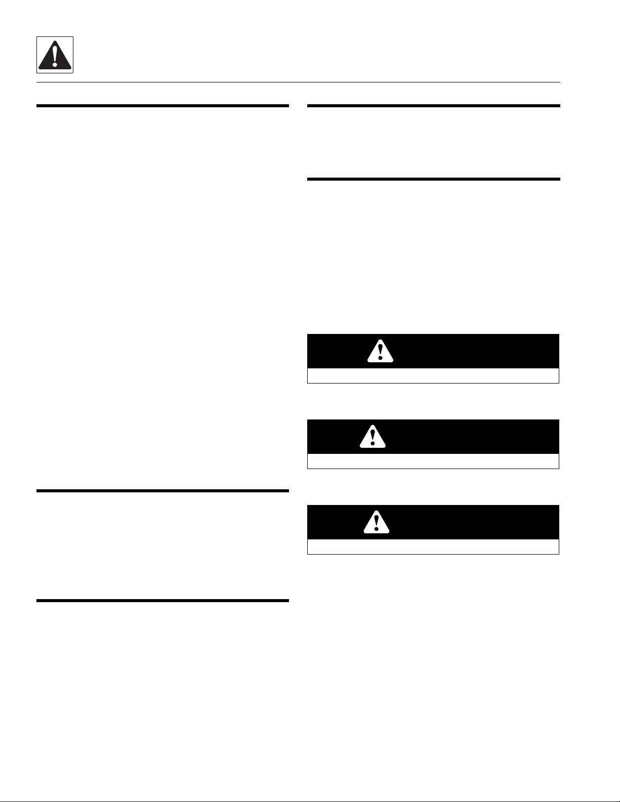
1.5.1 Safety Alert System and Signal Words
DANGER indicates an imminently hazardous situation
which, if not avoided, will result in death or serious injury.
WARNING indicates a potentially hazardous situation which,
if not avoided, could result in death or serious injury.
CAUTION indicates a potentially hazardous situation which,
if not avoided, may result in minor or moderate injury.
DANGER
WARNING
CAUTION

Safety Practices
1-3
6036, 6042, 8042, 10042, 10054 31211015
1.6 SAFETY INSTRUCTIONS
Following are general safety statements to consider before
performing maintenance procedures on the telehandler.
Additional statements related to specific tasks and
procedures are located throughout this manual and are
listed prior to any work instructions to provide safety
information before the potential of a hazard occurs.
For all safety messages, carefully read, understand and follow
the instructions before proceeding.
1.6.1 Personal Hazards
PERSONAL SAFETY GEAR: Wear all the protective clothing
and personal safety gear necessary to perform the job safely.
This might include heavy gloves, safety glasses or goggles,
filter mask or respirator, safety shoes or a hard hat.
LIFTING: NEVER lift a heavy object without the help of at
least one assistant or a suitable sling and hoist.
1.6.2 Equipment Hazards
LIFTING OF EQUIPMENT: Before using any lifting equipment
(chains, slings, brackets, hooks, etc.), verify that it is of the
proper capacity, in good working order, and is properly
attached.
NEVER stand or otherwise become positioned under a
suspended load or under raised equipment. The load or
equipment could fall or tip.
DO NOT use a hoist, jack or jack stands only to support
equipment. Always support equipment with the proper
capacity blocks or stands properly rated for the load.
HAND TOOLS: Always use the proper tool for the job; keep
tools clean and in good working order, and use special
service tools only as recommended.
1.6.3 General Hazards
SOLVENTS: Only use approved solvents that are known to be
safe for use.
HOUSEKEEPING: Keep the work area and operator cab clean,
and remove all hazards (debris, oil, tools, etc.).
FIRST AID: Immediately clean, dress and report all injuries
(cuts, abrasions, burns, etc.), no matter how minor the injury
may seem. Know the location of a First Aid Kit, and know how
to use it.
CLEANLINESS: Wear eye protection, and clean all
components with a high-pressure or steam cleaner before
attempting service.
When removing hydraulic components, plug hose ends and
connections to prevent excess leakage and contamination.
Place a suitable catch basin beneath the machine to capture
fluid run-off.
It is good practice to avoid pressure-washing electrical/
electronic components. In the event pressure-washing the
machine is needed, ensure the machine is shut down before
pressure-washing. Should pressure-washing be utilized to
wash areas containing electrical/electronic components, it is
recommended a maximum pressure of 750 psi (52 bar) at a
minimum distance of 12 in (30,5 cm) away from these
components. If electrical/electronic components are
sprayed, spraying must not be direct and for brief time
periods to avoid heavy saturation.
Check and obey all Federal, State and/or Local regulations
regarding waste storage, disposal and recycling.

Safety Practices
1-4 31211015 6036, 6042, 8042, 10042, 10054
1.6.4 Operational Hazards
ENGINE: Stop the engine before performing any service
unless specifically instructed otherwise.
VENTILATION: Avoid prolonged engine operation in
enclosed areas without adequate ventilation.
SOFT SURFACES AND SLOPES: NEVER work on a machine
that is parked on a soft surface or slope. The machine must be
on a hard level surface, with the wheels blocked before
performing any service.
FLUID TEMPERATURE: NEVER work on a machine when the
engine, cooling or hydraulic systems are hot. Hot
components and fluids can cause severe burns. Allow
systems to cool before proceeding.
FLUID PRESSURE: Before loosening any hydraulic or diesel
fuel component, hose or tube, turn the engine OFF. Wear
heavy, protective gloves and eye protection. NEVER check
for leaks using any part of your body; use a piece of
cardboard or wood instead. If injured, seek medical attention
immediately. Diesel fluid leaking under pressure can
explode. Hydraulic fluid and diesel fuel leaking under
pressure can penetrate the skin, cause infection, gangrene
and other serious personal injury.
Engine fuel lines are pressurized. DO NOT attempt repairs
unless specific training has been completed. Refer to the
engine manufacturers’ manual for specific details
concerning the fuel system.
Relieve all pressure before disconnecting any component,
part, line or hose. Slowly loosen parts and allow release of
residual pressure before removing any part or component.
Before starting the engine or applying pressure, use
components, parts, hoses and pipes that are in good
condition, connected properly and are tightened to the
proper torque. Capture fluid in an appropriate container and
dispose of in accordance with prevailing environmental
regulations.
COOLANT SYSTEM CAP: The cooling system is under
pressure, and escaping coolant can cause severe burns and
eye injury. To prevent personal injury, NEVER remove the
radiator cap while the cooling system is hot. Wear safety
glasses. Turn the radiator cap to the first stop and allow
pressure to escape before removing the cap completely.
Failure to follow the safety practices could result in death or
serious injury.
Properly disconnect battery(s) prior to service the fuel or
hydraulic systems.
FLUID FLAMABILTITY: DO NOT service the fuel or hydraulic
systems near an open flame, sparks or smoking materials.
NEVER drain or store fluids in an open container. Engine fuel
and hydraulic fluid are flammable and can cause a fire and/or
explosion.
DO NOT mix gasoline or alcohol with diesel fuel. The mixture
can cause an explosion.
PRESSURE TESTING: When conducting any test, only use test
equipment that is correctly calibrated and in good condition.
Use the correct equipment in the proper manner, and make
changes or repairs as indicated by the test procedure to
achieve the desired result.
LEAVING MACHINE: Lower the forks or attachment to the
ground before leaving the machine.
TIRES: Always keep tires inflated to the proper pressure to
help prevent tipover. DO NOT over-inflate tires.
NEVER use mismatched tire types, sizes or ply ratings.
Always use matched sets according to machine
specifications.
MAJOR COMPONENTS: Never alter, remove, or substitute any
items such as counterweights, tires, batteries or other items
that may reduce or affect the overall weight or stability of the
machine.
BATTERY: DO NOT charge a frozen battery.Charging a frozen
battery may cause it to explode. Allow the battery to thaw
before jump-starting or connecting a battery charger.
1.7 SAFETY DECALS
Check that all safety decals are present and readable on the
machine. Refer to the Operation & Safety Manual supplied
with machine for information.

2-1
6036, 6042, 8042, 10042, 10054 31211015
Section 2
General Information and Specifications
Contents
PARAGRAPH TITLE PAGE
2.1 Replacement Parts and Warranty Information . . . . . . . . . . . . . . . . . . . . . . . . . . . . . . . . . . . 2-3
2.2 Specifications . . . . . . . . . . . . . . . . . . . . . . . . . . . . . . . . . . . . . . . . . . . . . . . . . . . . . . . . . . . . . . . . . 2-4
2.2.1 Travel Speeds . . . . . . . . . . . . . . . . . . . . . . . . . . . . . . . . . . . . . . . . . . . . . . . . . . . . . . . . . . . . . . 2-4
2.2.2 Hydraulic Cylinder Performance . . . . . . . . . . . . . . . . . . . . . . . . . . . . . . . . . . . . . . . . . . . . 2-4
2.2.3 Electrical System . . . . . . . . . . . . . . . . . . . . . . . . . . . . . . . . . . . . . . . . . . . . . . . . . . . . . . . . . . . 2-5
2.2.4 Engine Performance Specifications . . . . . . . . . . . . . . . . . . . . . . . . . . . . . . . . . . . . . . . . . 2-5
2.2.5 Tires . . . . . . . . . . . . . . . . . . . . . . . . . . . . . . . . . . . . . . . . . . . . . . . . . . . . . . . . . . . . . . . . . . . . . . . 2-6
2.3 Fluid Specifications. . . . . . . . . . . . . . . . . . . . . . . . . . . . . . . . . . . . . . . . . . . . . . . . . . . . . . . . . . . . 2-7
2.4 Fluid and Lubricant Capacities . . . . . . . . . . . . . . . . . . . . . . . . . . . . . . . . . . . . . . . . . . . . . . . . . 2-9
2.5 Service and Maintenance Schedules . . . . . . . . . . . . . . . . . . . . . . . . . . . . . . . . . . . . . . . . . . . . 2-10
2.5.1 Every 10 Hours. . . . . . . . . . . . . . . . . . . . . . . . . . . . . . . . . . . . . . . . . . . . . . . . . . . . . . . . . . . . . 2-10
2.5.2 First 50 Hours . . . . . . . . . . . . . . . . . . . . . . . . . . . . . . . . . . . . . . . . . . . . . . . . . . . . . . . . . . . . . . 2-10
2.5.3 Every 50 Hours. . . . . . . . . . . . . . . . . . . . . . . . . . . . . . . . . . . . . . . . . . . . . . . . . . . . . . . . . . . . . 2-10
2.5.4 First 250 Hours. . . . . . . . . . . . . . . . . . . . . . . . . . . . . . . . . . . . . . . . . . . . . . . . . . . . . . . . . . . . . 2-10
2.5.5 Every 250 Hours . . . . . . . . . . . . . . . . . . . . . . . . . . . . . . . . . . . . . . . . . . . . . . . . . . . . . . . . . . . 2-11
2.5.6 First 500 Hours or 1 Year. . . . . . . . . . . . . . . . . . . . . . . . . . . . . . . . . . . . . . . . . . . . . . . . . . . . 2-11
2.5.7 Every 500 Hours . . . . . . . . . . . . . . . . . . . . . . . . . . . . . . . . . . . . . . . . . . . . . . . . . . . . . . . . . . . 2-11
2.5.8 Every 750 Hours . . . . . . . . . . . . . . . . . . . . . . . . . . . . . . . . . . . . . . . . . . . . . . . . . . . . . . . . . . . 2-11
2.5.9 Every 1000 Hours . . . . . . . . . . . . . . . . . . . . . . . . . . . . . . . . . . . . . . . . . . . . . . . . . . . . . . . . . . 2-12
2.5.10 Every 1500 Hours . . . . . . . . . . . . . . . . . . . . . . . . . . . . . . . . . . . . . . . . . . . . . . . . . . . . . . . . . . 2-12
2.5.11 Every 2000 Hours or 2 Year . . . . . . . . . . . . . . . . . . . . . . . . . . . . . . . . . . . . . . . . . . . . . . . . . 2-12
2.5.12 Every 4000 Hours or 3 Years . . . . . . . . . . . . . . . . . . . . . . . . . . . . . . . . . . . . . . . . . . . . . . . . 2-13
2.6 Lubrication Schedules . . . . . . . . . . . . . . . . . . . . . . . . . . . . . . . . . . . . . . . . . . . . . . . . . . . . . . . . . 2-14
2.6.1 50 Hour. . . . . . . . . . . . . . . . . . . . . . . . . . . . . . . . . . . . . . . . . . . . . . . . . . . . . . . . . . . . . . . . . . . . 2-14
2.6.2 250 Hour . . . . . . . . . . . . . . . . . . . . . . . . . . . . . . . . . . . . . . . . . . . . . . . . . . . . . . . . . . . . . . . . . . 2-17
2.6.3 1000 Hour . . . . . . . . . . . . . . . . . . . . . . . . . . . . . . . . . . . . . . . . . . . . . . . . . . . . . . . . . . . . . . . . . 2-19
2.7 Thread Locking Compound . . . . . . . . . . . . . . . . . . . . . . . . . . . . . . . . . . . . . . . . . . . . . . . . . . . . 2-20
2.8 Torque Charts . . . . . . . . . . . . . . . . . . . . . . . . . . . . . . . . . . . . . . . . . . . . . . . . . . . . . . . . . . . . . . . . . 2-21
2.8.1 SAE Fastener Torque Chart . . . . . . . . . . . . . . . . . . . . . . . . . . . . . . . . . . . . . . . . . . . . . . . . . 2-21
2.8.2 Metric Fastener Torque Chart. . . . . . . . . . . . . . . . . . . . . . . . . . . . . . . . . . . . . . . . . . . . . . . 2-27

General Information and Specifications
2-2 31211015 6036, 6042, 8042, 10042, 10054
2.9 Hydraulic Connection Assembly and Torque Specification . . . . . . . . . . . . . . . . . . . . . . . 2-31
2.9.1 Definitions . . . . . . . . . . . . . . . . . . . . . . . . . . . . . . . . . . . . . . . . . . . . . . . . . . . . . . . . . . . . . . . . . 2-31
2.9.2 Assembly Instructions for American Standard Pipe Thread Tapered Connections 2-33
2.9.3 Assembly Instructions for British Standard Pipe Thread Tapered Connections. 2-35
2.9.4 Assembly Instructions for 37° (JIC) Flare Fittings . . . . . . . . . . . . . . . . . . . . . . . . . . . . . 2-36
2.9.5 Assembly Instructions for 45° SAE Flare Fittings . . . . . . . . . . . . . . . . . . . . . . . . . . . . . 2-38
2.9.6 Assembly Instructions for O-Ring Face Seal (ORFS) Fittings. . . . . . . . . . . . . . . . . . . 2-40
2.9.7 Assembly Instructions for DIN 24° Flare Bite Type Fittings (MBTL and MBTS) . . 2-42
2.9.8 Assembly Instructions for Bulkhead (BH) Fittings . . . . . . . . . . . . . . . . . . . . . . . . . . . . 2-44
2.9.9 Assembly Instructions for O-Ring Boss (ORB) Fittings . . . . . . . . . . . . . . . . . . . . . . . . 2-48
2.9.10 Assembly Instructions for Adjustable Port End Metric Fittings . . . . . . . . . . . . . . . . 2-56
2.9.11 Assembly Instructions for Metric ISO 6149 Port Assembly Stud Ends . . . . . . . . . 2-64
2.9.12 Assembly Instructions for Adjustable Port End (BSPP) Fittings . . . . . . . . . . . . . . . . 2-66
2.9.13 Assembly Instructions for Flange Connections (FL61 and FL62) . . . . . . . . . . . . . . 2-74
2.9.14 Double Wrench Method . . . . . . . . . . . . . . . . . . . . . . . . . . . . . . . . . . . . . . . . . . . . . . . . . . . .2-77
2.9.15 FFWR and TFFT Methods . . . . . . . . . . . . . . . . . . . . . . . . . . . . . . . . . . . . . . . . . . . . . . . . . . .2-78
2.9.16 Adjustable Stud End Assembly. . . . . . . . . . . . . . . . . . . . . . . . . . . . . . . . . . . . . . . . . . . . . . 2-78
2.9.17 O-ring Installation (Replacement) . . . . . . . . . . . . . . . . . . . . . . . . . . . . . . . . . . . . . . . . . . . 2-78
General Information and Specifications
2-3
6036, 6042, 8042, 10042, 10054 31211015
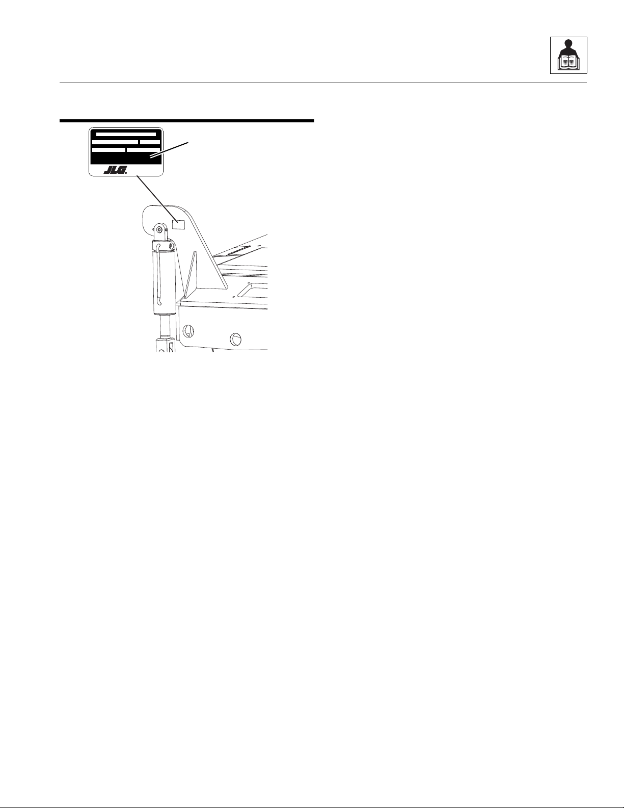
2.1 REPLACEMENT PARTS AND WARRANTY
INFORMATION
Before ordering parts or initiating service inquiries, make
note of the machine serial number. The machine serial
number plate (1) is located as indicated in the figure.
Note: The replacement of any part on this machine with any
other than JLG authorized replacement parts can adversely
affect the performance, durability, or safety of the machine,
and will void the warranty. JLG disclaims liability for any claims
or damages, whether regarding property damage, personal
injury or death arising out of the use of unauthorized
replacement parts.
A warranty registration form must be filled out by the JLG
distributor, signed by the purchaser and returned to JLG
when the machine is sold and/or put into use.
Registration activates the warranty period and helps to
assure that warranty claims are promptly processed. To
guarantee full warranty service, verify that the distributor has
returned the business reply card of the warranty registration
form to JLG.
1001154575A
* Refer to load capacity chart for truck with attachment, and individual load ratings stamped
on forks, if equipped. Usel owest capacity of all ratings.
As released from factory this truck meets design specifications i n ANSI \ IT SDF B56.6-2011
Manufactured by
JLG Industries Inc.
McCo nnell sburg , PA
17233-9533 USA
Maximum Weight Without Attachment s (lbs/kg) Maximum Capacity (lbs/kg)*
Seri al Numb er Year OfManufacture
Model
MAQ1570
1

General Information and Specifications
2-4 31211015 6036, 6042, 8042, 10042, 10054
2.2 SPECIFICATIONS
2.2.1 Travel Speeds
2.2.2 Hydraulic Cylinder Performance
Note: Machine with no attachment or load, engine at full throttle, hydraulic oil above 130° F (54° C) minimum, engine at operating
temperature.
TRANSMISSION 6036 6042 8042 10042 /10054
First Gear 3.6 mph
(5,8 km/hr)
3.6 mph
(5,8 km/hr)
3.6 mph
(5,8 km/hr)
3.7 mph
(6,0 km/hr)
Second Gear 6.1 mph
(9,8 km/hr)
6.1 mph
(9,8 km/hr)
5.8 mph
(9,3 km/hr)
6.1 mph
(9,8 km/hr)
Third Gear 14.5 mph
(23,3 km/hr)
14.5 mph
(23,3 km/hr)
13.8 mph
(23 km/hr)
14.5 mph
(23,3 km/hr)
Fourth Gear 19.5 mph
(31.4 km/hr)
19 mph
(30,6 km/hr)
19.0 mph
(30,6 km/hr)
20.0 mph
(32,2 km/hr)
FUNCTION
APPROXIMATE TIMES (seconds)
6036 6042 8042 10042 10054
Boom Extend Less than 14.0 Less than 18.0 Less than 17.0 Less than 17.0 Less than 18.0
Boom Retract Less than 15.0 Less than 18.0 Less than 16.0 Less than 16.0 Less than 16.0
Boom Lift Retracted Less than 12.0 Less than 15.0 Less than 17.0 Less than 17.0 Less than 17.0
Boom Lower Retracted Less than 10.0 Less than 11.0 Less than 17.0 Less than 17.0 Less than 15.0
Attachment Tilt - Up 5 5 7.5 7.5 8
Attachment Tilt - Down 6 6 8 8 10
Frame Level Left to Right
with Boom Down 12 - 14 12.0 - 14.0 12.0 - 14.0 12.0 - 14.0 12.0 - 14.0
Frame Level Left to Right
with Boom Above 40°and
Emergency Brake
Engaged
— 23.0 - 33.0 23.0 - 33.0 23.0 - 33.0 23.0 - 33.0
Frame Level Right to Left
with Boom Down 12 - 14 12.0 - 14.0 12.0 - 14.0 12.0 - 14.0 12.0 - 14.0
Frame Level Right to Left
with Boom Above 40°and
Emergency Brake
Engaged
— 26.0 - 52.0 26.0 - 52.0 26.0 - 52.0 26.0 - 52.0
Outrigger - Left or Right,
UP or DOWN — — — 4.0 - 9.0 4.0 - 9.0
Outrigger - Left and Right,
UP or DOWN — — — 4.0 - 10.0 4.0 - 10.0

General Information and Specifications
2-5
6036, 6042, 8042, 10042, 10054 31211015
2.2.3 Electrical System
2.2.4 Engine Performance Specifications
Note: No adjustment of the throttle is required. The engine Low Idle and High Idle are controlled by the engine ECM and cannot be
adjusted without Cummins programing tools.
Battery
Type, Rating 12 BCI, Negative (-) Ground, Maintenance Free
Quantity 1
Cold Cranking Amps 3.8 Liter - 950 CCA @ 0° F (-18° C)
Reserve Capacity 205 Minutes @ 80° F (27° C)
Group/Series Group 31 - 950
Alternator 12V, 135 Amps
Description 6036 & 6042
If Equipped for ULS
6036 & 6042
If Equipped for LS
6036 & 6042
If Equipped w/ 74hp (55kW)
Engine Make/Model Cummins Turbo QSF3.8 Cummins Turbo QSF3.8 Cummins Turbo QSF3.8
Displacement 232 in3(3,8 liters) 232 in3(3,8 liters) 232 in3(3,8 liters)
Low Idle (no load) 1000 rpm 1000 rpm 1000 rpm
High Idle (no load) 2500 rpm 2500 rpm 2500 rpm
Horsepower 85 hp (63 kW) @ 2500 rpm 85 hp (63 kW) @ 2500 rpm 74 hp (55 kW) @ 2500 rpm
Peak Torque 340 lb-ft (461 Nm) @ 1400 rpm 340 lb-ft (461 Nm) @ 1400 rpm 295 lb-ft (400 Nm) @ 1300 rpm
Fuel Delivery High Pressure Common Rail (HPCR) Fuel Injection
Air Cleaner Dry Type, Replaceable Primary and Safety Elements
Description 8042, 10042 & 10054
If Equipped for ULS
8042, 10042 & 10054
If Equipped for LS
8042, 10042 & 10054
If Equipped w/ 74hp (55kW)
Engine Make/Model Cummins Turbo QSF3.8 Cummins Turbo QSF3.8 Cummins Turbo QSF3.8
Displacement 232 in3(3,8 liters) 232 in3(3,8 liters) 232 in3(3,8 liters)
Low Idle 1000 rpm 1000 rpm 1000 rpm
High Idle 2500 rpm 2500 rpm 2500 rpm
Horsepower 110 hp (82 kW) @ 2500 rpm 110 hp (82 kW) @ 2500 rpm 74 hp (55 kW) @ 2500 rpm
Peak Torque 348 lb-ft (472 Nm) @ 1500 rpm 348 lb-ft (472 Nm) @ 1500 rpm 295 lb-ft (400 Nm) @ 1300 rpm
Fuel Delivery High Pressure Common Rail (HPCR) Fuel Injection
Air Cleaner Dry Type, Replaceable Primary and Safety Elements

General Information and Specifications
2-6 31211015 6036, 6042, 8042, 10042, 10054
2.2.5 Tires
Note: Standard wheel lug nut torque is 350 - 400 lb-ft (474 - 542 Nm).
Note: Pressure for foam filled tires are for initial fill ONLY.
a. 6036
b. 6042
c. 8042
d. 10042 & 10054
Size Tire Type Minimum Ply/
Star Rating
Fill Type Pressure
13.0 x 24 G-2/L2 Bias Ply Traction 12 Ply Pneumatic 70 psi (4,8 bar)
Foam - Approx 542 lb (246 kg)
13.0 x 24 Solid Tires NA NA NA
15.5 x 25 G2/L-2 Bias Ply Traction 12 Ply Pneumatic 70 psi (4,8 bar)
Foam - Approx 600 lb (272 kg)
370/75x28 DuraForce 14 Ply Pneumatic 76 psi (5,2 bar)
Foam - Approx 464 lb (210 kg)
Size Tire Type Minimum Ply/
Star Rating
Fill Type Pressure
13.0 x 24 G-2/L-2 Bias Ply Traction 12 Ply
Pneumatic 70 psi (4,8 bar)
Foam - Approx 542 lb (246 kg)
TG/G-3 Bias Ply Grader Foam - Approx 542 lb (246 kg)
13.0 x 24 Solid Tires NA NA NA
15.5 x 25 G-2/L-2 Bias Ply Traction 12 Ply Pneumatic 70 psi (4,8 bar)
Foam - Approx 600 lb (272 kg)
370/75x28 DuraForce 14 Ply Pneumatic 76 psi (5,2 bar)
Foam - Approx 464 lb (210 kg)
Size Tire Type Minimum Ply/
Star Rating
Fill Type Pressure
13.0 x 24 Solid Tires NA NA NA
15.5 x 25 G-2/L-2 Bias Ply Traction 12 Ply Pneumatic 70 psi (4,8 bar)
Foam - Approx 600 lb (272 kg)
370/75x28 DuraForce 14 Ply Pneumatic 76 psi (5,2 bar)
Foam - Approx 464 lb (210 kg)
Size Tire Type Minimum Ply/
Star Rating
Fill Type Pressure
14.0 x 24 Solid Tires NA NA NA
17.50 x 25 G-2/L-2 Bias Ply Traction 12 Ply Pneumatic 70 psi (4,8 bar)
Foam - Approx 785 lb (356 kg)
400/75x28 DuraForce 14 Ply Pneumatic 76 psi (5,2 bar)
Foam - Approx 570 lb (259 kg)

General Information and Specifications
2-7
6036, 6042, 8042, 10042, 10054 31211015
2.3 FLUID SPECIFICATIONS
If Equipped for ULS
Note: *Friction Modifier may be added to axle differentials, see Section 2.4, “Fluid and Lubricant Capacities”.
**See Note on page 2-12 for details.
Compartment or System Type and Classification Viscosities
Ambient Temperature
Range
°F °C
Min Max Min Max
Engine Crankcase
API CJ-4 Plus
CES-20081
Fully Synthetic**
SAE 0W-30 -12 114 -24 45
SAE 5W-30 15 114 -10 45
SAE 10W-30 10 104 -24 40
SAE 15W-40 -40 104 -40 40
Transmission and Transfer Case
MobilFluid 424 10W-30 15 120 -10 49
MobilFluidLT 75W-80 -2015-29-10
Refer to ZF TE-ML-03 for additional fluids.
Axle Differential and Wheel End
MobilFluid 424* 10W-30 15 120 -10 49
Mobilfluid LT* 75W-80 -20 15 -29 -10
API GL4 with LS Additives
or
API GL5 with LS Additives
75W-90 -20 114 -29 45
Hydraulic System MobilFluid 424 10W-30 15 120 -10 49
Exxon Univis HVI 26 -20 120 -29 49
Boom Wear Pad Grease Extreme Pressure Grease NLGI Grade 000 -31 122 -35 50
Grease Fittings Extreme Pressure Grease
NLGI Grade 2 EP
or
NLGI Grade 3 EP
with Moly
Additive
5122-1550
Boom Chain Lubricant Gear Oil 80W-90 -40 115 -40 46
Engine Coolant Ethylene Glycol
and Water
50/50 Mix Standard
60/40 Mix Cold Weather
Fuel
EN590
ASTM D975 Grade 2-D
ASTM D975 Grade 1-D
(Maximum B5 Biodiesel)
Ultra Low Sulfur
(S <15 mg/kg)
Diesel Exhaust Fluid (DEF)
85 hp (63 kW) or 110 hp (82 kW) ISO22241-1 32.5% Urea
Brake Fluid
(SN 0160074878 to Present) Mobil ATF-D/M -20 114 -29 45
Air Conditioning Refrigerant R-134A Tetrafluoroethane

General Information and Specifications
2-8 31211015 6036, 6042, 8042, 10042, 10054
If Equipped for LS
Note: *Friction Modifier may be added to axle differentials, see Section 2.4, “Fluid and Lubricant Capacities”.
Compartment or System Type and Classification Viscosities
Ambient
Temperature Range
°F °C
Min Max Min Max
Engine Crankcase API CI-4 Multigrade
CES-20078
SAE 0W-30 -20 0 -29 -18
SAE 5W-30 -15 70 -26 21
SAE 10W-30 -9 70 -22 21
SAE 15W-40 5 120 -15 49
Transmission and Transfer Case
Mobilfluid 424 10W-30 15 120 -10 49
MobilFluid LT 75W-80 -20 15 -29 -10
Refer to ZF TE-ML-03 for additional fluids.
Axle Differential and Wheel End
MobilFluid 424 10W-30 15 120 -10 49
Mobilfluid LT* 75W-80 -20 15 -29 -10
API GL4 with LS Additives
or
API GL5 with LS Additives
75W-90 -20 114 -29 45
Hydraulic System MobilFluid 424 10W-30 15 120 -10 49
Exxon Univis HVI 26 -20 120 -29 49
Boom Wear Pad Grease Extreme Pressure Grease NLGI Grade 000 -31 122 -35 50
Grease Fittings Extreme Pressure Grease
NLGI Grade 2 EP
or
NLGI Grade 3 EP
with Moly
Additive
5122-1550
Boom Chain Lubricant Gear Oil 80W-90 -40 115 -40 46
Engine Coolant Ethylene Glycol
and Water
50/50 Mix Standard
60/40 Mix Cold Weather
Fuel
EN590
ASTM D975 Grade 2-D
ASTM D975 Grade 1-D
(Maximum B5 Biodiesel)
Low Sulfur
(S < 500 mg/kg)
Brake Fluid
(SN 0160074878 to Present) Mobil ATF-D/M -20 114 -29 45
Air Conditioning Refrigerant R-134A Tetrafluoroethane
This manual suits for next models
4
Table of contents
Other Skytrak Lifting System manuals

Popular Lifting System manuals by other brands


Plymovent
Plymovent Balancer Series user manual

Tractel Group
Tractel Group pakrol 1 Operating and maintenance instructions

SICE
SICE PT 150 E Operator's manual

Safety Clamps
Safety Clamps VL-BC Operation, maintenance, and repair manual

Monument
Monument 1043J instructions

Monzana
Monzana Deuba DBWH001 instructions

stellar labs
stellar labs 108-14-32 owner's manual

BYD
BYD ECB16 Operator's manual

Sirio Antenne
Sirio Antenne SRS1351 - I user manual

morse
morse 515M-T-114 Operator's manual

twin busch
twin busch TW 125 M Installation, operation and maintenance manual

Proactive
Proactive Protekt Take-A-Long 33400P owner's manual