EG4 WPOWER-16/280-AW User manual
© 2023 EG4 ELECTRONICS, LLC. ALL RIGHTS RESERVED.
VERSION 1.1 | INFORMATION SUBJECT TO CHANGE WITHOUT NOTICE.
MODEL #: WPOWER-16/280-AW
USER MANUAL
LITHIUM BATTERY
POWERPRO WALLMOUNT
ALL-WEATHER BATTERY
SCAN FOR UPDATED
DOCUMENTS


TABLE OF CONTENTS
1. TECHNICAL SPECIFICATIONS SHEET............................................................................................................. 1
2. ABBREVIATIONS............................................................................................................................................... 3
3. SAFETY............................................................................................................................................................... 4
3.1 SAFETY INSTRUCTIONS............................................................................................................................... 4
3.2 IMPORTANT SAFETY NOTIFICATIONS...................................................................................................... 4
4. BRIEF INTRODUCTION .................................................................................................................................... 6
4.1 PRODUCT DESCRIPTION.............................................................................................................................. 6
5. PACKING LIST.....................................................................................................................................................7
6. BATTERY OVERVIEW....................................................................................................................................... 8
6.1 BATTERY DIAGRAM...................................................................................................................................... 9
7. LOCATION SELECTION AND INSTALLATION..............................................................................................10
7.1 POWERPRO CONDUIT BOX INSTALLATION............................................................................................ 11
7.2 INSTALLATION WITHOUT A CONDUIT BOX ........................................................................................... 14
7.3 INSTALLATION WITH A CONDUIT BOX ....................................................................................................15
7.4 WITH EG4 18KPV INVERTER..................................................................................................................17
8. GENERAL INSTALLATION ..............................................................................................................................21
8.1 BATTERY PARALLELING GUIDE.................................................................................................................21
8.2 BATTERY CABLE CONNECTIONS..........................................................................................................22
8.3 ADDITIONAL CONFIGURATIONS .......................................................................................................... 23
9. EMERGENCY STOP (RSD, ESS DISCONNECT)........................................................................................... 26
10. BATTERY COMMUNICATIONS ..................................................................................................................... 27
10.1 DIP SWITCH ID TABLE ............................................................................................................................ 27
10.2 LCD SCREEN .............................................................................................................................................28
10.3 COMMUNICATION PROTOCOL SELECTION........................................................................................29
11. OPERATION GUIDE..........................................................................................................................................31
11.1 BMS TOOLS INSTALLATION AND INTERFACING ...............................................................................31
12. BATTERY CHARGING .....................................................................................................................................34
12.1 BATTERY PERFORMANCE CURVES..................................................................................................... 35
13. TROUBLESHOOTING, MAINTENANCE & DISPOSAL................................................................................36
13.1 INTRODUCTION TO THE BMS............................................................................................................... 36
13.2 BMS PROTECTION .................................................................................................................................. 36
13.3 TROUBLESHOOTING............................................................................................................................... 37
13.4 BATTERY END OF LIFE........................................................................................................................... 39
14. EG4 10 YEAR LIMITED WARRANTY ............................................................................................................39
14.1 WARRANTY EXCLUSIONS ..................................................................................................................... 39
15. STORAGE..........................................................................................................................................................40

1
1. TECHNICAL SPECIFICATIONS SHEET
MODULE OPERATING PARAMETERS
Parameter
BMS
Recommended Charger Settings
Total Energy Capacity
14.3kWh @25C, 100% SOC
Voltage
51.2V
-
Capacity
280Ah ±2%
@25°C ±2°C @ 0.5C
Charging Voltage (Bulk/Absorb)
56.0V (±0.8V)
56.2V (±0.2V)
Float
-
54V (±0.2V)
Low DC Cuto 44.8V
47-45.6V
(start higher, lower as needed)
Charge Current
100/140/200A
Max. Continuous**
60 - 160A
Discharge Current
200A Max. Continuous
160A
ENVIRONMENTAL PARAMETERS
Charging Range
32° to ≈113°F (0°C to ≈45°C)
Discharging Range
-4°F to ≈122°F (-20°C to ≈50°C)
Storage Range
-4°F to ≈122°F (-20°C to ≈50°C)
Ingress Protection
IP65
CHARGING/DISCHARGING PARAMETERS
Charge
Spec
Delay
Recovery
Cell Voltage Protection
3.8V
1 sec
3.45V
Module Voltage Protection
60V
1 sec
55.2V
Charge Over-Current 1
>205A
10 sec
-
Charge Over-Current 2
>225A
3 sec
-
Temperature Protection
<23°F or >158°F
<-5°C or >70°C
1 sec
>32°F or <140°F
>0°C or <60°C
Discharge
Spec
Delay
Recovery
Cell Voltage Protection
2.3V
1 sec
3.1V
Module Voltage Protection
44.8V
1 sec
48V
Discharge Over-Current 1
>205A
10 sec
60 sec
Discharge Over-Current 2
>300A
3 sec
60 sec
Short Circuit
2000A
0.1 ms
-
Temperature Protection
<-4°F or >167°F
<-20°C or >75°C
1 sec
>14°F or <149°F
>-10°C or <65°C
PCB Temperature Protection
>230°F (>110°C)
1 sec
@ <176°F (<80°C)
GENERAL SPECIFICATIONS
Parameter
Spec
Condition
Cell Balance 120mA Passive Balance Cell Voltage Dierence
>40mV
Temperature Accuracy 3% Cycle Measurement
Measure Range:
-40 – ≈212°F (-40 – ≈100°C)
Voltage Accuracy
0.5%
Cycle Measurement
Cells & Module
Current Accuracy 3% Cycle Measurement
Measure Range:
-200 – 200A
SOC
5%
Integral Calculation
Power Consumption
(Standby)
<300uA Standby/Storage
Power Consumption
(Operating)
<25mA Charging/Discharging
Communication Ports
RS485/CAN
Customizable

2
BATTERY HEATER SPECIFICATIONS
Parameter
Spec
Condition
Voltage
56V
-
Power Consumption
224W
-
Internal Battery Temperature
≤32°F (0°C) or ≥41°F (5°C)
Heat On/Heat O
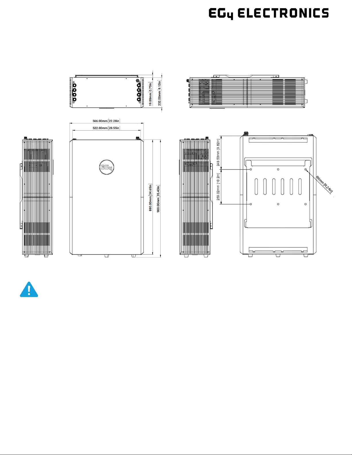
PHYSICAL SPECIFICATIONS
Dimensions (H × W × D)
34.6 × 22.3 × 9.1 in. (88 × 56.6 × 23.2cm)
Weight
308.6 lbs. (140 kg)
Design Life
>15 years
Cycle Life
>8000 Cycles @ 0.5C 80% DOD
Lifetime Production
82.6MWh*
*(51.2V×280Ah/1000×80%×8000 cycles/1000)90%=MWh
**Note: The default BMS in the module allows for 100A charging current maximum. To achieve higher charging currents,
please contact your distributor for optional firmware files, or navigate to https://eg4electronics.com/downloads/ for
the most up to date firmware.

3
2. ABBREVIATIONS
AWG – American Wire Gauge
A – Amp(s)
Ah – Amp hour(s)
AC – Alternating Current
AHJ – Authority Having Jurisdiction
ANSI – American National Standards Institute
BMS – Battery Management System
DC – Direct Current
DIP – Dual In-line Package
DOD – Depth of Discharge
EG – Equipment Ground
EGS – Equipment Grounding System
EPS – Emergency Power System
ESS – Energy Storage System
E-Stop NO – Emergency Stop Normally Open
GE – Grounding Electrode
GEC – Grounding Electrode Conductor
GES – Grounding Electrode System
Imp – Maximum Power Point Current
Isc – Short-Circuit Current
In. lbs. – Inch Pounds
kW – Kilowatt
kWh – Kilowatt-hour
LFP – Lithium Iron Phosphate or LiFePO4
mm – Millimeter(s)
ms – Millisecond(s)
mV – Millivolt(s)
NEC – National Electrical Code
NFPA – National Fire Prevention Association
Nm – Newton Meters
PC – Personal Computer
PCB – Printed Circuit Board
PE – Protective Earth (G or Ground)
PPE – Personal Protective Equipment
PV – Photovoltaic
RSD – Rapid Shut Down
SOC – State of Charge
STC – Standard Testing Conditions
V – Volt(s)
VOC – Open-Circuit Voltage
VMP – Voltage Maximum Power

4
3. SAFETY
3.1 SAFETY INSTRUCTIONS
International safety regulations have been strictly observed in the design and
testing of the inverter. Before beginning any work, carefully read all safety
instructions, and always observe them when working on or with the inverter. The
installation must follow all applicable national or local standards and regulations.
Incorrect installation may cause:
•injury or death to the installer, operator or third party
•damage to the inverter or other attached equipment
3.2 IMPORTANT SAFETY NOTIFICATIONS
There are various safety concerns that must be carefully observed before, during,
and after the installation, as well as during future operation and maintenance. The
following are important safety notifications for the installer and any end users of
this product under normal operating conditions.
1. Beware of high PV voltage. Please install an external DC disconnect switch or
breaker and ensure it is in the “o” or “open” position before installing or
working on the inverter. Use a voltmeter to confirm there is no DC voltage
present to avoid electric shock.
2. Beware of high grid voltage. Please ensure the AC switch and/or AC breaker are in
the “o” or “open” position before installing or working on the inverter. Use a
voltmeter to confirm there is no voltage present to avoid electric shock.
3. Beware of high battery current. Please ensure that the battery module breakers
and/or on/o switches are in the “open” or “o” position before installing or
working on the inverter. Use a voltmeter to confirm there is no DC voltage present
to avoid electric shock.
4. Do not open the inverter while it is operating to avoid electric shock and
damage from live voltage and current within the system.
5. Do not make any connections or disconnections (PV, battery, grid, communication, etc.)
while the inverter is operating.
6. An installer should make sure to be well protected by reasonable and
professional insulative equipment [e.g., personal protective equipment (PPE)].
7. Before installing, operating, or maintaining the system, it is important to
inspect all existing wiring to ensure that it meets the appropriate
specifications and conditions for use.
8. Ensure that the PV, battery, and grid connections to the inverter are secure
and proper to prevent damage or injuries caused by improper installation.
DANGER! Hazardous Voltage Circuits!
AVERTISSEMENT! Circuits à tension élevée!

5
All work on this product (system design, installation, operation, setting, configuration, and
maintenance) must be carried out by qualified personnel. To reduce the risk of electric
shock, do not perform any servicing other than those specified in the operating instructions
unless you are qualified to do so.
1. Read all instructions before installing. For electrical work, follow all local and national
wiring standards, regulations, and these installation instructions.
2. Make sure the inverter is properly grounded. All wiring should be in accordance with the
National Electrical Code (NEC), ANSI/NFPA 70.
3. The inverter and system can inter-connect with the utility grid only if the utility provider
permits. Consult with your local AHJ (Authority Having Jurisdiction) before installing this
product for any additional regulations and requirements for your area.
4. All warning labels and nameplates on this inverter should be clearly visible and must not be
removed or covered.
5. The installer should consider the safety of future users when choosing the inverter’s correct
position and location as specified in this manual.
6. Please keep children away from touching or misusing the inverter and relevant systems.
7. Beware! The inverter and some parts of the system can be hot when in use, please do not
touch the inverter’s surface or most of the parts when they are operating. During operation,
only the LCD and buttons should be touched.
DISCLAIMER
EG4 reserves the right to make changes to the material herein at any time without notice.
Please refer to www.eg4electronics.com for the most updated version of our manuals/spec sheets.
WARNING: To reduce the risk of injury, read all instructions

6
4. BRIEF INTRODUCTION
Battery Features
•Constant rated output current of 200A
•IP65 all-weather rated, integrated self-heating during low ambient temperatures.
•Smart balancing of cells enhancing the battery consistency and the lifespan up to 15 years of
life with over 8000 cycles at 80% DOD at 0.5C
•Built-in intelligent BMS with battery voltage, current, temperature, and health management
to reduce electrical risks and overheating
•Internal busbars rated to 600 Amps for paralleling multiple batteries and feeding multiple
inverters
•Real time monitoring and LCD screen to display battery voltage, current, temperature, SOC in
detail
•Integrated E-stop circuit supports emergency stop function with remote Rapid Shutdown
Initiator (RSD) or Energy Storage Systems (ESS) disconnect or by inverter’s RSD or ESS
terminals
•Communicate with inverter using CAN or RS485. Firmware update using RS485
•Plug-and-play cable installation with the use of the 250A weather-tight quick connectors
•Stable, reliable, and maintenance-free battery pack
•Comprehensive safety UL9540A, UL1973 on cell and module level with enhanced onboard
fire-extinguishing modules.
4.1 PRODUCT DESCRIPTION
The EG4® 48V PowerPro WallMount All Weather 280Ah batteries are ideal for low-voltage
residential outdoor energy storage system (ESS) applications. These batteries use lithium iron
phosphate (LiFePO4 or LFP) cells with the highest safety performance and an intelligent Battery
Management System (BMS) that can monitor and record the voltage of each cell, along with the
current, voltage, and temperature of the module in real-time. The BMS also contains a passive
balance function and an advanced battery control method, both of which improve the
performance of the battery pack. For enhanced security, the battery has two onboard fire-
extinguishing modules. With a design life of more than 15 years, the WallMount is designed to last
over 8000 cycles at 80% DOD at 0.5C°.
7
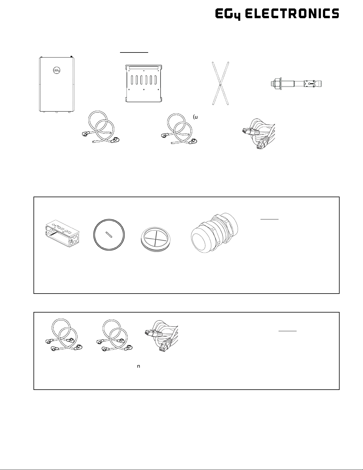
5. PACKING LIST
The items listed below are included with the purchase:
280Ah Battery
(Qty 1)
X-Bracket
(used for EG4-18kPV)
Concrete
expansion bolts
M8×70 (Qty 6)
Mounting
bracket (Qty 1)
Battery to Inverter
communication cable
(Qty 1)
Red power cable 2/0 AWG
39.4 in (to inverter
positive terminal) (Qty 2)
Black power cable 2/0
AWG 39.4 in (to inverter
negative terminal) (Qty 2)
Black battery
parallel cable 53.1 in
(Qty 1)
Parallel
communication
cable 59.1 in (Qty 1)
Red battery parallel
cable 53.1 in (Qty 1)
The following items are included in the optional
Battery Paralleling kit
•Red positive battery parallel cable 53.1 in. (Qty 1)
•Black negative battery parallel cable 53.1 in. (Qty 1)
•Parallel Communication cable 59.1 in. (Qty 1)
PowerPro Conduit
Box (Qty 1)
Conduit box
plugs (Qty 9)
Rubber / plastic
grommets between
battery and conduit
box (Qty 9)
Cable glands for
conduit box (Qty 16)
The following Items are included in
the optional conduit box kit
•Conduit box (Qty 1)
•Conduit box plugs (Qty 9)
•Rubber/plastic grommets
between battery and conduit box
(Qty 9)
•Cable glands for conduit box 1, 1.5
and 2.5in knockouts (Qty 16)
Figure 1 – Packing List
Figure 2 – Conduit Box Packing List
Figure 3 – Parallel Kit Packing List
8
6. BATTERY OVERVIEW
When installing or removing battery, ensure battery is in the o position, and use a voltmeter to
confirm there is no voltage present. This will prevent users from encountering live (powered)
terminals by accident.
Failure to do so can result in severe injury and/or death.
Figure 4 – Battery Cross-Sectional View
DANGER
9
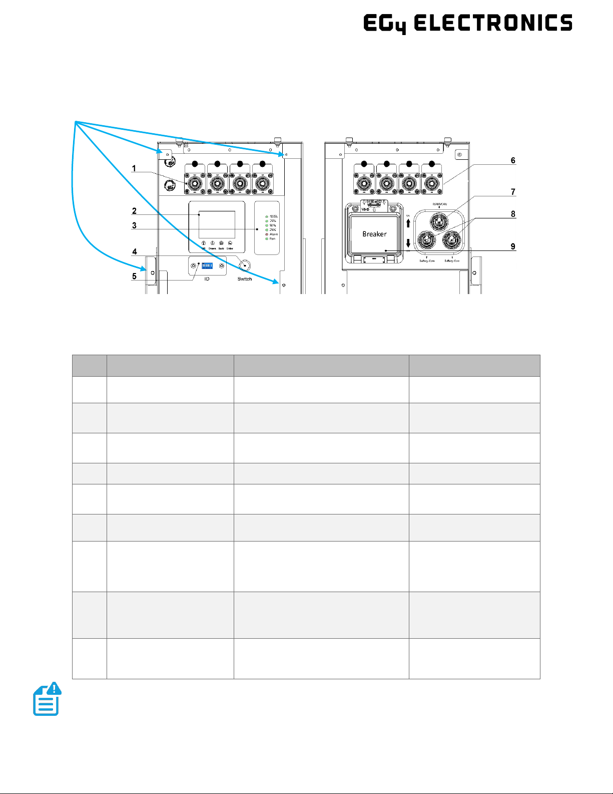
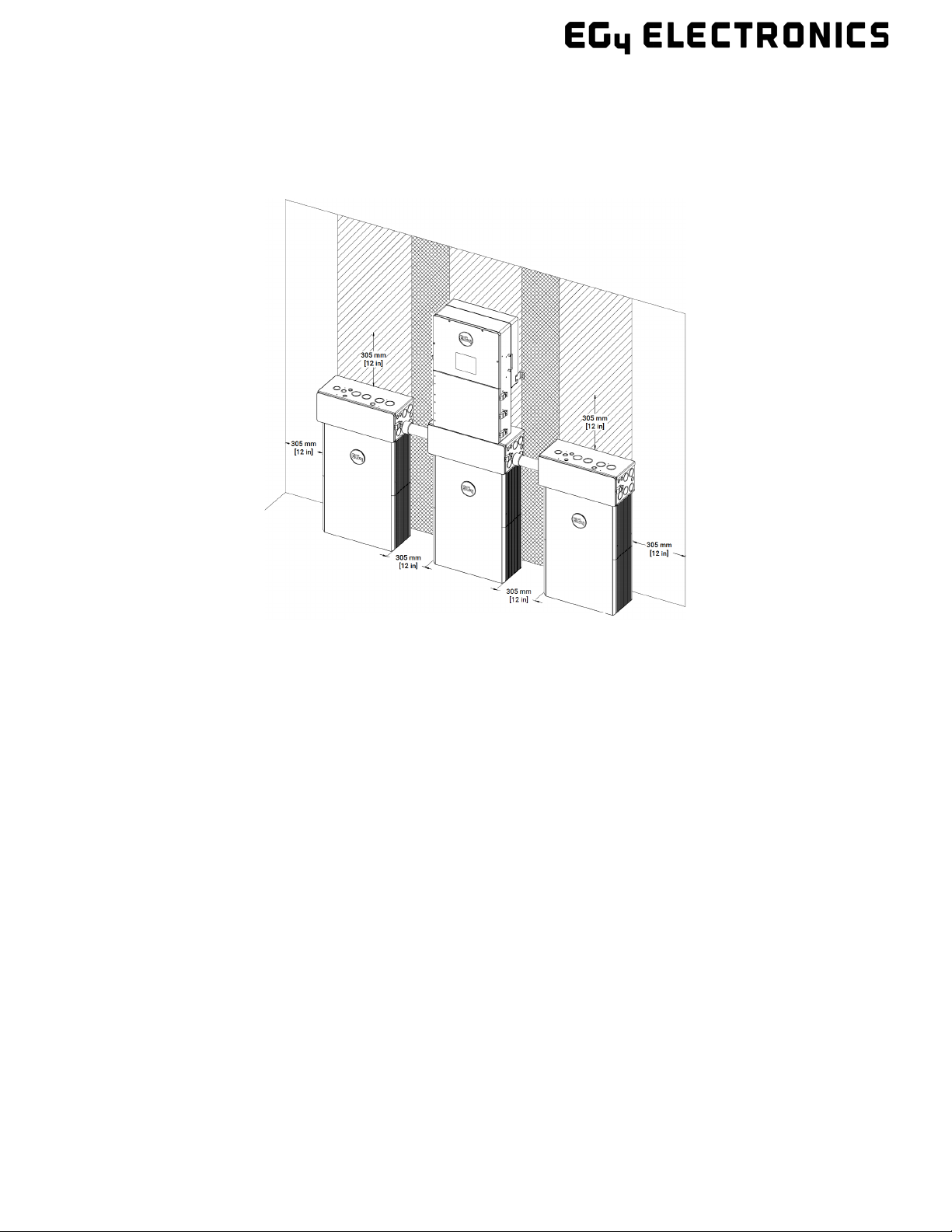
6.1 BATTERY DIAGRAM
It is highly recommended to install the battery with at least 12-inch clearance on each side ofthe battery
(back and front sides excluded) to easily access the side panel.
NO. ITEM DESCRIPTION REMARKS
1 Negative Terminals
Connects to negative terminal of
Inverter and/or paralleled battery
2 LCD Screen Shows battery information
3 SOC Display State of Charge LED
4 Power Switch Turns BMS on/o
5 ID/DIP Switch DIP Switch board for BMS
6 Positive Terminal Connects to positive terminal of
Inverter and/or paralleled battery
7 RS485/CAN Port RS485/CAN Communication
Interface
Pin 1 & Pin 8 ‒RS485_B
Pin 2 & Pin 7 – RS485_A
Pin 4 – CAN_H
Pin 5 – CAN_L
8 Battery-Comm Parallel battery Communication
Port
Pin 1 & Pin 8 ‒RS485_B
Pin 2 & Pin 7 – RS485_A
Pin 3 & Pin 6 ‒E-Stop NO
9 Battery Disconnect
Breaker Turns power supply on/o
Double Pole Single Throw
125 Frame size
125A Rating
*
NOTE: Additional hardware may be required to remove the side terminal covers. EG4 recommends a
3mm width, 90mm length #2 Phillips head screwdriver
Figure 5 – Battery (side view)
Side Panel Screws
Side A
Side B
*NOTE: The battery disconnect breaker is 2 single pole breakers with a singular
switch, paralleled together to reach a 250A Rating.

10
7. LOCATION SELECTION AND INSTALLATION
•Do not put EG4 48V batteries in series. The BMS and internal components are not designed to
handle this setup, which could cause the modules to fail.
•Do NOT mix EG4 WallMount 280Ah batteries with any non-280Ah lithium batteries. This will
void your warranty.
•The WallMount is heavy. Use a lift or other equipment to lift and carry the unit
•The WallMount can be installed on either flat ground or on the wall. If installed on flat ground,
ensure there is proper drainage on the ground surrounding the battery to maintain integrity of
the module over time. If installing on the wall, ensure at least a 12 in. gap on each side of the
unit for adequate airflow and operations.
•Install the WallMount in a location that prevents damage from flooding
•Always mount the battery in an upright position.
•WallMount must be installed with clearance at the left, right, top, bottom, and front of the
product for easy installation and safe operation of the unit as shown in the above picture.
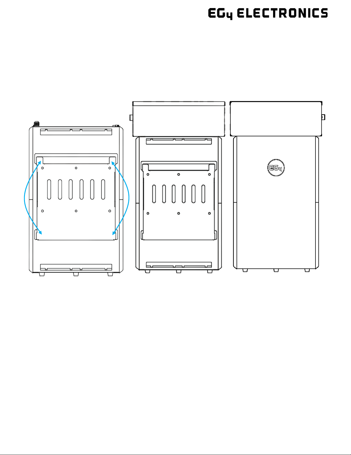
Back View
Temporary Lifting
Handles
Figure 6 – Battery Lifting Handles
WARNING
NOTE: The battery will be shipped with temporary lifting handles for removing the
battery from its packaging. See image below for location. EG4 recommends removing
the handles before connecting any wiring to the battery.
11
•Ensure at least 12 in. between multiple WallMount batteries and other devices, unless it is
installed as a part of PowerPro WallMount ESS that includes EG4-18kPV with the conduit box.
In a PowerPro WallMount ESS installation, the conduit box is attached directly to both battery
and inverter.
•Please follow NEC and other local codes while installing the product.
The battery can be installed in multiple dierent configurations:
1. Installation without a conduit box (Sec 7.2)
2. Installation with a conduit box (Sec 7.3)
3. Installation with EG4 18kPV inverter (Sec 7.4)
Refer to Section 7.3 for multiple battery installations with multiple EG4-18kPV units.
7.1 POWERPRO CONDUIT BOX INSTALLATION
The conduit box is a highly recommended accessory for the battery to retain all the cables inside an
enclosure for added protection and safety. The conduit box holds both the conduits and wires that are
running between the inverter and the battery.
Each Conduit box comes with 8 thumb screws that can be used to attach the inverter and the battery.
Figure
7 – Clearance Diagram
12
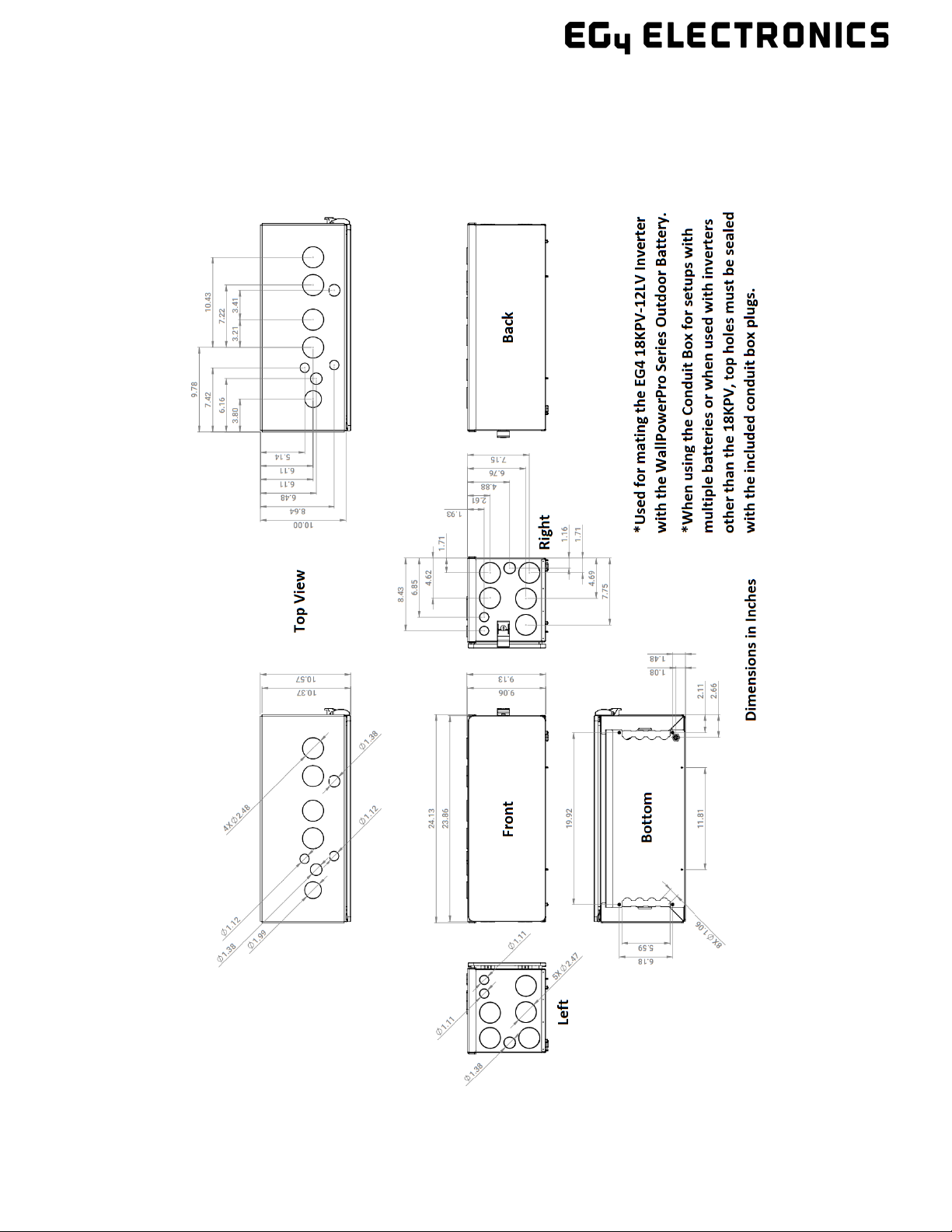
Figure 8 – Conduit Box Schematics
13
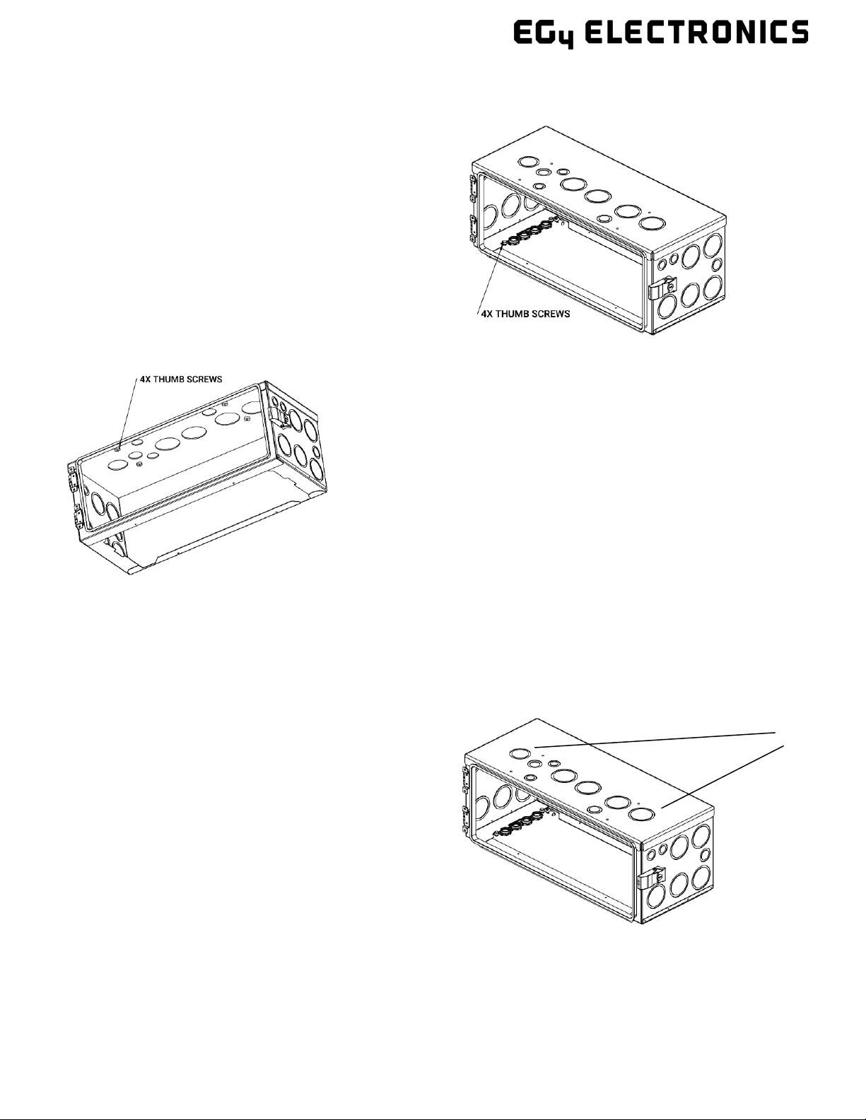
Step 1: Identify the four screw locations that attach to the battery (Figure 9). Place the conduit box on
top of the battery and use the provided thumb screws to tighten the conduit box to the battery.
Step 2: If you are installing the WallMount along with the 18kPV
inverter (Sec 7.4), please use the remaining 4 thumb screws on
the top side of the conduit box to secure it to the inverter, as
shown in Figure 10.
If you are installing the WallMount as an additional battery or along with non-EG4 18kPV inverter
(Section 7.3), please use the plugs to cover the top holes on the conduit box. Refer to Figure 11.
Plugs
Figure 9 – Conduit Box Thumb Screws
Figure 10 – Conduit Box Thumb Screws
Figure 11 – Conduit Box Plug Location

14
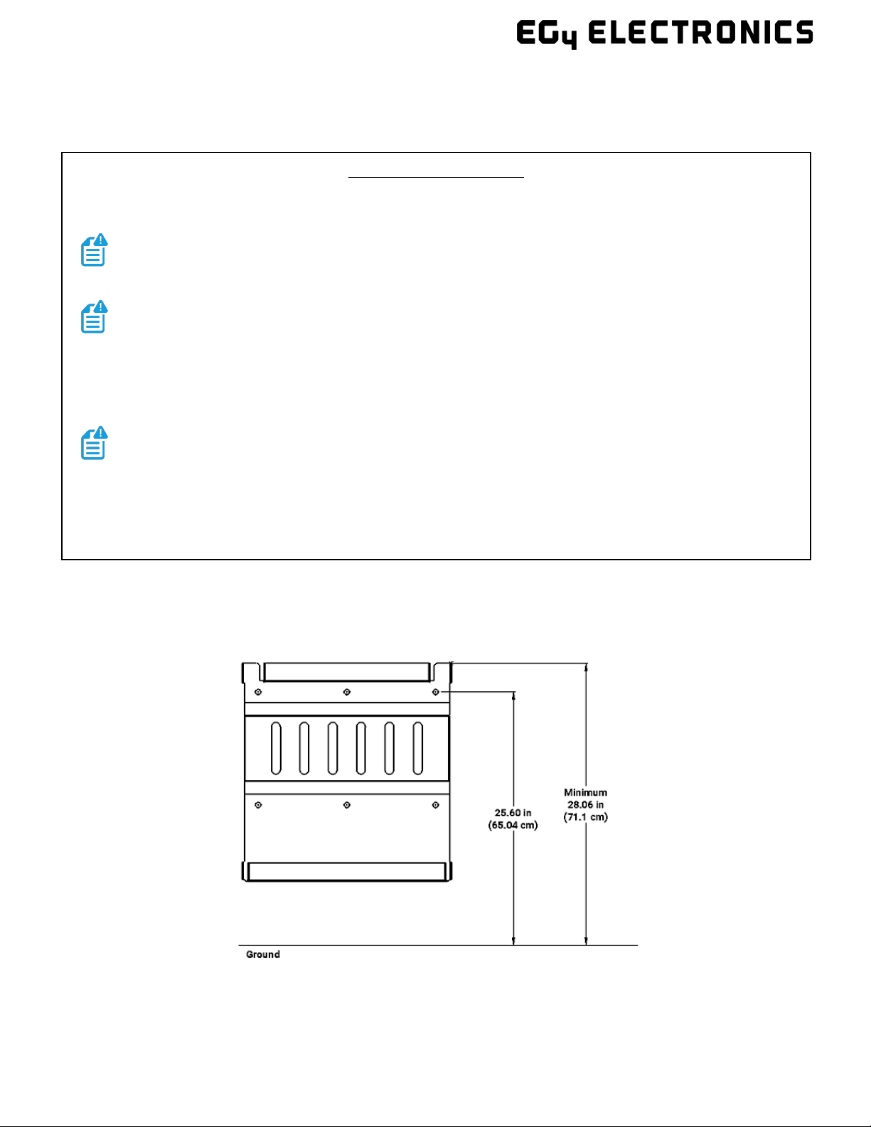
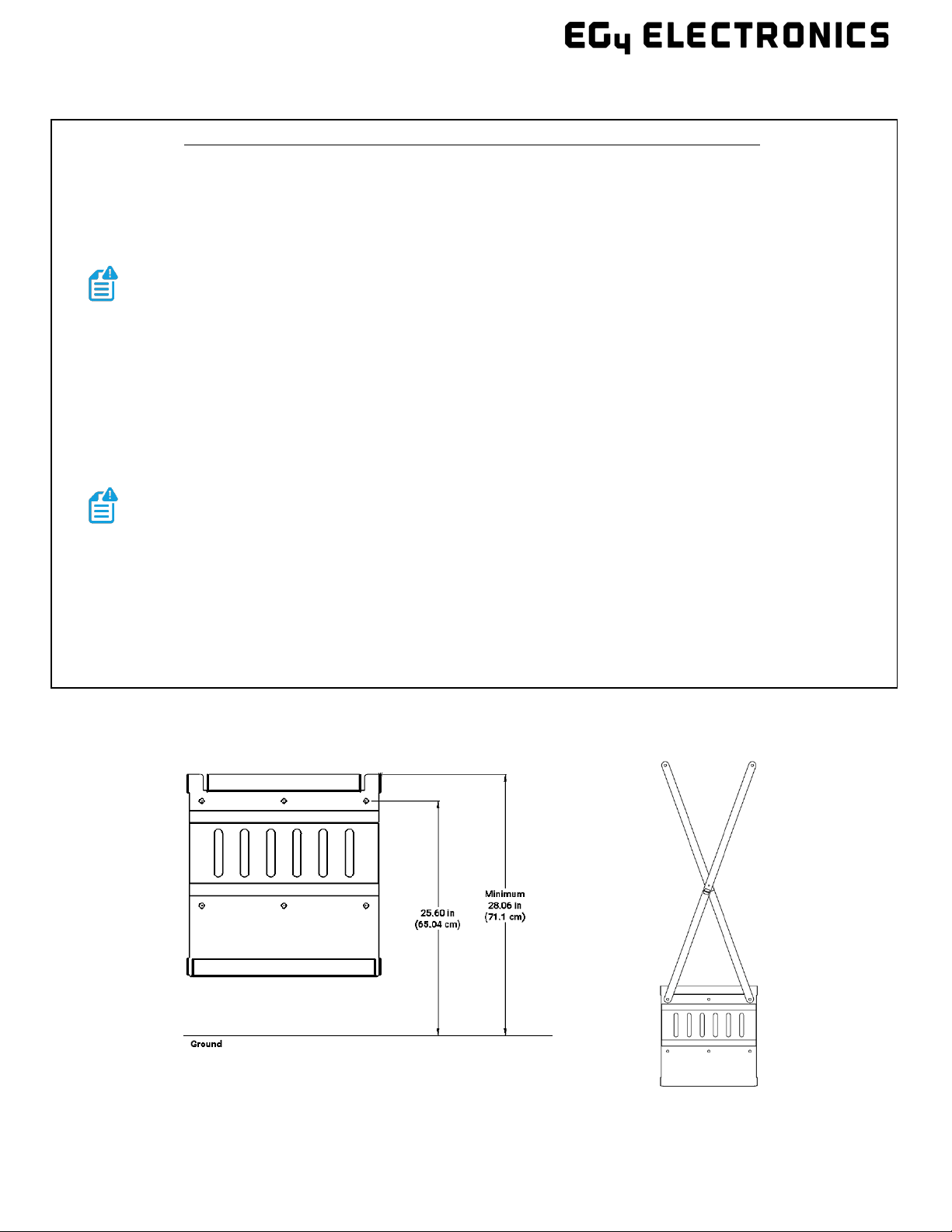
7.2 INSTALLATION WITHOUT A CONDUIT BOX
Mounting Instructions
1. Place mounting bracket on wall at proper mounting height (Min. 28.0625 in) from the ground; use a
Level to make sure the bracket is straight, and mark mounting hole locations. Drill holes to
accommodate mounting hardware being used.
Note: The mounting bracket at 28.065in from the ground makes the battery sit on the ground.
2. Secure mounting bracket to the wall using the included expansion bolts (concrete/brick walls) or
appropriate hardware required for the mounting surface.
Note: If not mounting into concrete or brick using the included expansion bolts, ensure bolts are
mounted into both studs or other supportive material. The battery is 300lbs, please ensure full
mounting support.
3. Attach the WallMount battery pack to the mounting bracket. To accomplish this, lift the battery up
and hook the flange on the back of the battery into the flange on the front of the mounting bracket.
Secure the battery to the mounting bracket with the 4 included side screws (see Figure 12)
Note: The battery is very heavy. Please use the team lift technique to prevent damage to personnel
and/or equipment
4. Finally, properly ground the battery, attaching a grounding conductor to the M6 grounding screw on
top of the battery to the Equipment Grounding System.
Steps 1 & 2
Completed Install
Step 3
Figure 12 – WallMount Installation without Conduit Box
Secure Points
15
7.3 INSTALLATION WITH A CONDUIT BOX
Attach the conduit box (sold separately) to the top of the WallMount battery using the included
hardware. Refer to Section 7.1 for the conduit box installation instructions.
Mounting Instructions
1. Place mounting bracket on wall at proper mounting height (minimum 28.0625 in) from the ground;
use a Level to make sure the bracket is straight, and mark mounting hole locations. Drill holes to
accommodate mounting hardware being used.
Note: The mounting bracket at 28.065in from the ground makes the battery sit on the ground.
2. Secure mounting bracket to the wall using the included expansion bolts (concrete/brick walls) or
appropriate hardware required for the mounting surface.
Note: If not mounting into concrete or brick using the included expansion bolts, ensure bolts are
mounted into both studs or other supportive material. The battery is 300lb, please ensure full
mounting support.
3. Attach the WallMount battery pack to the mounting bracket. To accomplish this, lift the battery up
and hook the flange on the back of the battery into the flange on the front of the mounting bracket.
Secure the battery to the mounting bracket with the 4 included side screws (see Figure 14)
Note: The battery is very heavy. Please use the team lift technique to prevent damage to
personnel and/or equipment
4. Attach the conduit box (sold separately) to the top of the WallMount battery using the included
hardware.
5. Finally, properly ground the battery, attaching a grounding conductor to the M6 grounding screw
on top of the battery to the Equipment Grounding System.
Steps 1 & 2
Figure 13 – WallMount Installation with Conduit Box Steps 1 & 2
16
Step 4
Final-Front View
Step 3
Secure Points
Figure 14 – WallMount Installation with Conduit Box Steps 3, 4 & 5
17
7.4 WITH EG4 18KPV INVERTER
Step 2 (back view)
Mounting Instructions with EG4 18kPV (See diagrams on following pages)
Note: If not mounting into concrete or brick using the included expansion bolts, ensure bolts are mounted
into both studs or other supportive material. The battery is 300lb, please ensure full mounting support.
1. Place mounting bracket on wall at proper mounting height (Min. 28.0625 in) from the ground; use a
Level to make sure the bracket is straight, and mark mounting hole locations. Drill holes to
accommodate mounting hardware being used.
Note: The mounting bracket at 28.065in from the ground makes the battery sit on the ground.
2. Align the provided X-bracket with the holes on the mounting bracket and secure both to the wall,
using the included expansion bolts (concrete/brick walls) or appropriate hardware required for the
mounting surface. The X-bracket will be behind the mounting plate, against the wall.
3. Using the X-bracket as a guide, attach the EG4 18kPV mounting bracket using the appropriate
hardware required for the mounting surface.
4. Attach the WallMount battery pack to the mounting bracket. To accomplish this, lift the battery up
and hook the flange on the back of the battery into the flange on the front of the mounting bracket.
Secure the battery to the mounting bracket with the 4 included side screws (see Figure 16).
Note: The battery is very heavy. Please use the team lift technique to prevent damage to personnel
and/or equipment
5. Attach the conduit box (sold separately) to the top of the WallMount battery using the included
hardware.
6. Attach the 18kPV to the inverter mounting bracket making sure that the holes of the inverter align
with the conduit box and secure to each other with the included hardware.
7. Finally, properly ground the battery, attaching a grounding conductor to the M6 grounding screw on
top of the battery to the Equipment Grounding System.
Step 1 (front view)
Figure 15 – WallMount Installation with Conduit Box & 18kPV Steps 1 & 2
Table of contents
Other EG4 Batteries Pack manuals


Popular Batteries Pack manuals by other brands


Husqvarna
Husqvarna BLi100 Workshop manual

Sony
Sony VAIO VGP-BPSC24 operating instructions

Power works
Power works LB60A00PW owner's manual

Bosch
Bosch PowerPack Frame 800 Original operating instructions

Inventus Power
Inventus Power PROTRXion S-24V80-TRX quick start guide

Panasonic
Panasonic CF-VZSU0PW operating instructions


