RV12100 User Manual
©Dyness reserves the copyright of this document.
1 Introduction
Brief Introduction
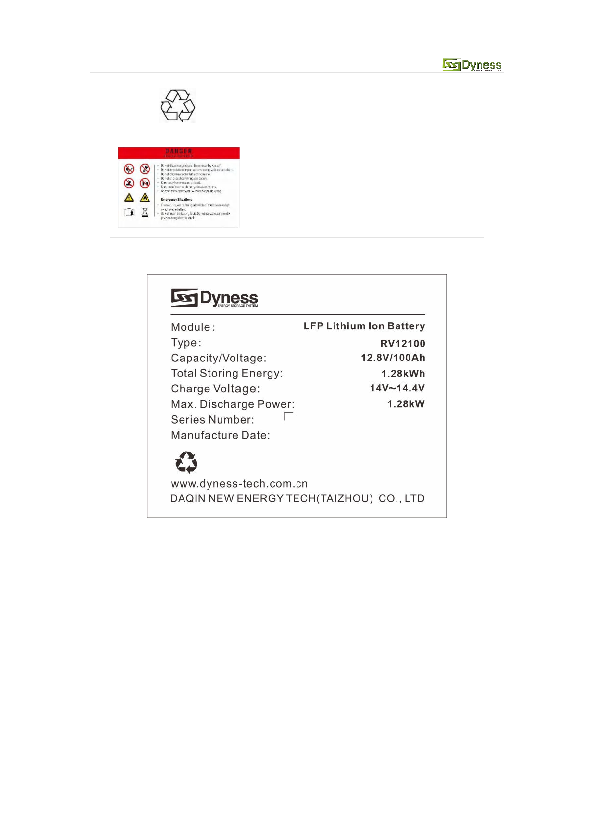
RV12100 lithium iron phosphate battery system is a standard battery system unit,
customers can choose a certain number of RV12100 according to their needs, by
connecting parallel to form a larger capacity battery pack, to meet the user's long-term
power supply needs.(It is forbidden to use in series)
Product Properties
RV12100 energy storage product's anode materials are lithium iron phosphate, battery
cells are managed effectively by BMS with better performance, the system's features as
below:
Comply with European ROHS, Certified SGS, employ non-toxic, non-pollution
environment-friendly battery;
Anode materials are lithium iron phosphate (LiFePO4), safer with longer life span;
Carries battery management system with better performance, possesses protection
function like over-discharge, over-charge, over-current, abnormal temperature;
Self-management on charging and discharging, Single core balancing function;
Flexible configurations allow parallel of multi battery for longer supply time;
Self-ventilation with lower system noise;
Less battery self-discharge, then recharging period can be up to 6 months during the
storage; No memory effect so that battery can be charged and discharged shallowly;
With wide range of temperature for working environment, -20oC ~ +55 oC, circulation
span and discharging performance are well under high temperature;
Less volume, lighter weight.
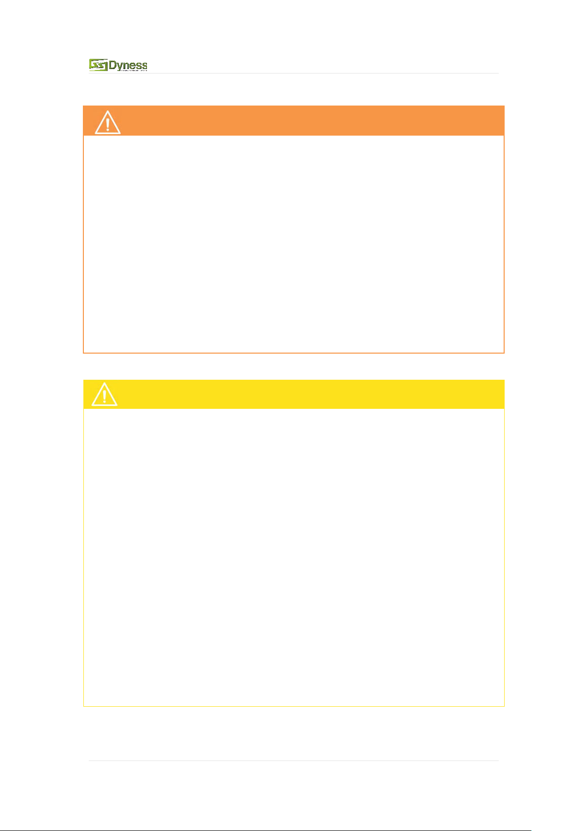
Product identity definition
Battery voltage is higher than safe voltage,
direct contact with electric shock hazard
Be careful with your actions and be aware of
the dangers
Read the user manual before using
The scrapped battery cannot be put into the
garbage can and must be professionally
recycled