EGAmaster 79617 User manual

OPERATING INSTRUCTIONS
MANUEL D’INSTRUCTIONS
RECIPROCATING SAWS
SCIE PORTABLE PNEUMATIQUE
COD.79617
COD.79618
ENGLISH................................ 2
FRANÇAIS............................ 28
GUARANTEE / GARANTIE ... 56

2
TECHNICAL SPECIFICATION
Type COD. 79617 COD. 79618
Operating pressure 6 bar 6 bar
Motor output 1.1 kW 1.1 kW
Stroke number (under load) 330 1/min. 330 1/min.
Stroke of saw blade 60 mm 60 mm
Air consumption 1.45 m³/min. 1.45 m³/min.
Air connection R ¾” male R ¾” male
Operating pressure 6 bar 6 bar
Weight approx. 6.4 kg 10.65 kg
Cutting capacity for pipes Ø 530 mm Ø 530 mm
Cutting capacity for proles 290 mm 290 mm
Vibration level at free speed < 2.5 m/s² < 2.5 m/s²
Noise level at 1 m distance 84 dB (A) 84 dB (A)
ENGLISH

3
SAFETY INSTRUCTIONS
Any power tool can be dangerous.
Please follow these simple procedures.
They are for your protection.
Wear goggles ( chips – risk of injury)
Wear gloves (cutting damages by sharp edged work pieces)
Wear safety shoes
Wear protective clothing
Remove rings, watches, ties etc. that could be torn by the machine.
Dress properly. Do not wear loose clothing or jewellery, it can be caught in moving parts.
Follow the general current and appropriate Accident Prevention and Safety Procedures.
Never work under the inuence of alcohol, drugs or stronger medication.
Always make sure that you have a safe foothold.
Maintain a proper footing and balance at all time. Never work with the machine while standing
on a ladder or leaning against a scaffold.
Secure the working place well. Use clamps or a vice to x the work piece. This is safer than
using hands and clears both hands for operating the machine.
Hold the machine tight during operation.
Keep your working area clean and uncluttered.
Keep children away and avoid other persons to come into contact with the machine.
Switch off the machine if it stops - for any reason - to avoid the unexpected starting in
uncontrolled condition.
Do not operate the tool if it is damaged, improperly adjusted or not completely and correctly
assembled.
Check air hose for damage.
Work with oleiferous air only.

4
Avoid sparks in hazardous environment - created by the saw blade. Always ush material and
saw blade for cooling with sufcient water during working.
Do not employ machines by excessive force. Their performance is better and safer, if they work
at the prescribed speed.
Check damaged parts.
Before using the machine, damaged parts or protective devices should be carefully checked to
make sure they work soundly and full the designated function. Check alignment, connections
and attachment of moving parts. Also check if parts are broken. Parts or protective devices that are
damaged should, if nothing else is mentioned in these operating instructions, only be exchanged
or repaired by qualied personnel. The same applies to defective switches and valve triggers. If the
machine cannot be switched on or off with the valve trigger, it should not be used.
The use of other accessories, or other additional items than recommended in these operating
instructions, may include the risk of bodily injury.
Only operate the tool after a thorough training or under supervision of a trainer.
Never exceed the maximum operation pressure.
Follow the valid national provisions in the country of application.
ATTENTION! Never use the exible hose as a lifting handle!
USE
INTENDED USE
Skilled personnel only is allowed to operate the machine.
The machine (reciprocating saw) serves for cutting (shortening, cutting off to length) of different
materials and proles. Mainly the saw will be used xed in a clamping device that is
corresponding to the intended purpose.
But cutting without clamping device is also possible!
IMPROPER USE
Any use deviating from the intended use as described is considered to be improper use.
Working without personal protection equipment.

5
Danger Zones
Operational
condition Normal function Malfunction Improper use Expected use
Life phase
Transport
Transport of
the machine in
an inoperable
condition
Drop of the
machine
Transport of
the machine
in an operable
condition
unknown
Start-up
Operation
Operating the
machine with
designated device
unknown unknown Working without
device
Operation
Machine only
works with
actuated valve
Machine runs
without actuated
valve
Switch is blocked
in actuated
condition
unknown
Machine moves
the tool Tool blocks unknown unknown
Maintenance Operation at a
maintenance unit
Breakdown of the
machine unknown unknown
OPERATION INSTRUCTIONS
GENERAL
Our pneumatic saw is designed for a service pressure of 4 to 6 bar. The pneumatic reciprocating
saw is only used in conjunction with a clamping device. For this purpose the ground- in
receiving bolt of the clamping device is placed in the cross hole in gear casing cover and xed by
means of the locking device. Firmly clamped work-piece will yield a clean cut and will reduce saw
blade damage. The selection of the clamping device and of the saw blade depends on the type and
size of the work-piece. The saw blade must be cooled and/ or lubricated with lubricant or oil.
CUTTING
- Check oil level and ll up oiler, if neccessary.
- Equip saw with the appropriate saw blade. For this loosen two nuts, take away the pressure
plate and put in the saw blade. Mount the pressure plate and x it to the saw blade by tightening
the nuts.

6
- Connect pneumatic hose. (Before connecting, it is recommended to blow out the hose and thus
remove impurities).
- Actuate valve and press sensor button. (Only after pressing the sensor button, the channel is
opened. When the valve is closed, the sensor shuts as well. When the valve is opened again, the
sensor button has to be pressed again as well.)
- Start cutting.
- Ensure appropriate cooling (water) of tool and working piece.
AFTER FINISHING THE SAWING WORK
- Shut valve
- Shut compresse air supply and disconnect air hose.
- Take saw out of the device.
- Clean saw and retainer seat.
- Check oiler
MAINTENANCE INSTRUCTIONS
Our pneumatic motors are designed for an operation pressure of 4 -6 bar (65-90 PSI).
Service life and performance of the machines are decisively determined by:
a) The air purity
Blow the air hose clear before connecting it to the machine. Install dirt and water separator
upstream of the machine, if it is not possible to prevent the formation of rust and water
condensation in the air distribution lines.
b) The lubrication conditions and maintenance
see “Maintenance of pneumatic tools“
The proper quantity of grease is very important from the point of good lubrication and low heat
generation. The grease quantities listened in the following table must be complied with:
Grease Quantity in grams
In the crank casing 100
In the bevel gears 40
In the spur gears 30

7
MAINTENANCE OF PNEUMATIC TOOLS
Only proper maintenance can ensure constant performance, reduction in wear and thus, a
decrease in operating costs and an increase in service life.
Our pneumatic tools are equipped for an operating pressure of 6 bar. A regulator setting for an
operating pressure of 4 bar is possible as well as expedient for grinding machines with a built-in
regulator so as to take full advantage of the speed prescribed for the corresponding grinding wheels.
Pneumatic tools should not run empty, because this results in heat and higher wear. The
compressed air should be clean and dry.
This is guaranteed by a proper pneumatic system.
Blow through the pneumatic hose before connecting it.
For the economical use of pneumatic tools. The prescribed air quantities are necessary, i. e. , the
line, armatures and hoses must have the required cross sections so that the ow pressure remains
constant.
Proper lubrication is a must; for this reason, our pneumatic tools usually have built-in oilers.
Which are located between the inlet valve and the motor, and which function in any position. In
smaller and lighter hand tools, these oilers must often be left out, because the machines would then
be too heavy and not easy to manage. In such cases, lubrication must be carried out by service
units or by manual hose oilers. We recommend service units for permanently installed workplaces
(see accessories list). However, where longer hose lines are necessary.
Line oilers built into the hose lines are more effective. The distance between the tool and oiler
should not be more than 5 m.
Most of pneumatic tools have located at the connection a lined-up screen, which is to be
regularly checked and cleaned.
After ending a working task, the machines are to be ushed with a thin oil, or protected some
other way against corrosion.
Visible grease nipples ar provided for regular lubrication of the gears with a grease gun. Note the
following for grease lubrication: Every 60 hours of operation check striking mechanism, friction
bearings and antifriction bearings; if necessary, grease them. Every 300 hours of operation grease
the gears and antifriction bearings anew. In the case of impact wrenches, use a grease gun to
grease the anvil guide before beginning daily work or every 6 to 8 hours. All inner parts must be
lubricated before storing for longer periods of time in order to prevent rusting. It is recommended
to check the vanes and bearings at regular intervals. Store pneumatic tools in dry rooms only.
Lubricating oils to be used:
Generally SAE 5 W to SAE 10
For gearless impact wrenches and small grinders, only SAE 5 W.
For damp compressed air, oils are to be used that take up water ( without losing the lubricating
effect) and that contain anticorrosive additives. At lower temperatures (especially for work
outside) it may be necessary to use an antifreeze lubricant (e.g. Kilfrost, BP Energol AX 10,
Kompranol N 74).
For saw-chain lubrication on chain saws:
Machine oil with adhesive additive, viscosity c ST 49-55’ (6.5-7.5 E)/ 50°C

8
Greases ( free of resins and
acids)
Multi-purpose greases for
antifriction and friction
bearings
Special greases for high-speed
miter gears
Designation in accordance
with DIN 51502 Consistency
class (DIN 51818)
Saponication type Dripping
point Worked penetration
Temperature range
K L 2 k
2
Lithium
185 °C
265 to 295
-25°C to + 125°C
G 000 h
00
Sodium
145°C
400 to 410
-25°C to + 100°C
Before starting: Check correct oiler setting!
Oiler types used on or with our tools
Oiler to mount on the machine or connect in
the hose line
Setting the oiler: The adjustment screw item 2
is visible after removing the screw plug item
3. Theoil supply is decreased by tightening
the screw, and by loosening the screw, more
oil gets into the machine. In most cases it is
sufcient to tighten or loosen the screw by ¼
or ½ of a turn. When plugged, clean borehole
(dia. 2 mm) with wire.
Correct setting; When under pressure and with
the ller screw (item 4) open, the oil must
bubble slightly. The llint lasts for approx. 8
operating hours.
Line oiler
For stationary pneumatic machines and motors,
the lubrication is carried out by lined-up oilers
for horizontal or vertical installation.
Setting of oilers: Shut off air supply. Open plug
item 3. Loosen visible lock nut item 5 with a
socket wrench. Using a screw driver turn back
the tightened screw plug item 4 by ¼ to ½ of
a turn and then lock again. No oil is to get into
the borehole “a” when lling. Close plug item 3
and open the air supply.
Correct setting: A piece of paper held for a short
time in front of the outlet must be coated with
oil without drops forming.

9
Transparent oiler
For installing in permanently equipped
workplaces (especially for type using service
units – see accessories list)
The transparent supply containers allow for
good checking as well as for good setting
possibility by means of a screw driver via a set
screw with visible dripping. (The set screw is
above the lateral thread connection – turning
to the right for less oil; turning to the left for
more oil) The setting (2 to 5 drops per m³/min
air consumption) is to be carried out when air
is owing through, i.e., when the machine is
running.
SPARE PARTS AND ACCESSORIES
Only original spare parts may be used. There is no warranty for damages and liability is
disclaimed, if non-original spare parts and accessories are used.
The repairing of the machine is allowed authorized expert companies only.
The accessories applicable with our machine are listed in our brochure.
TROUBLES HOOTING
Problem Cause Remedy
aMachine does not start Air not connected Connect and open air line
bMachine rotates too
slowly
Operating pressure too
low
Increase operating
pressure (on the machine
) to 6 bar
cGearbox makes strong
noise
Contact authorized expert
company
dOther problems Contact authorized expert
company
REPAIR INSTRUCTION
Disassembly and re-assembly
Dismantling and assembly should only be carried out using the sectional drawing.
Gearbox
Loosen the 2 cap nuts item 94 and 2 screws item 97 and pull out the motor with sealing disc
item 16, bearing item 43 and drive block item 35 from the gear housing item 30. Disconnect the

10
drive block from the rotor and disassemble (watch out for the compensating ring item 47).
Loosen the screws item 88 and 89, remove the gear box cover item 70 and connecting rod item 77.
Remove the screws item 65, pull out the crankshaft item 51 with bearing plate item 62.
Pay attention to compensating ring item 49.
Motor
Unscrew the governor casing item 25 with complete valve. Extract the rotary sleeve item 18
from motor housing.
Motor components as end plate item 7, cylinder bushing item 4, rotor item 11 and end plate
item 13 are pressed forwards out of the motor housing und unscrew the weight clip item 19 from
rear rotor pivot (left-hand thread) and disassemble motor. Check all parts for wear and damage and
replace, if necessary.
Assembly
Assembly is carried out essentially using the reverse procedure. The correct distancing of the
motor must be observed. The axial play between rotor and the end plates should be approx.
0.04mm in both sides. Screws items 79 and hexagonal nuts item 87 for fastening of connecting rod
item 78 must be tightened with 15 Nm and connected with Loctite 242. Tighten cap nuts item
94 with 4 Nm.

11
SPARE PARTS
Only original spare parts may be used. There is no warranty for damages and liability is
disclaimed, if non-original spare parts and accessories are used.
Pneumatic Reciprocating Saw. COD. 79617 / COD. 79618
Qty. Description
1 Motor, Assy.
1Gearbox head, Assy.
Motor, Assy. COD. 79617
Item Qty. Remarks
1 1
2 1 *
3 1 *
4 1
5 2
1 * With ítem 7-10
7 1 *
8 1
9 1
10 1 *
11 1
12 4 *
13 1 *
14 1 *
15 1
16 1
17 1 *
18 1
19 1
20 10
21 2
22 1
23 1
24 1
25 1
26 1
26 1
27 4
28 1
320 1 See extra list
* Wear and tear parts to be stored in case of continuous use.

12

13
Twist valve
Item Qty. Description Remarks
301 1 Valve housing, Assy. with item 312
302 1 Twist valve
303 1 Steel ball
304 1 Steel ball
305 1 Sealing *
306 1 Pressure spring
307 2 O-Ring *
308 1 Connecting nipple
311 1 Locking screw
312 1 Adjusting screw
313 1 Sealing *
314 1 Locking screw
315 1 Sealing *
* Wear and tear parts to be stored in case of continuous use.
14
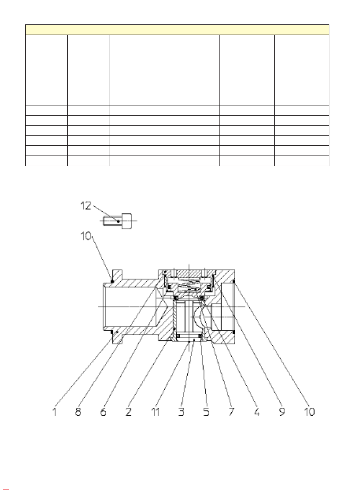
Sensor Block
Item Qty. Description Remarks
1 1 Sensor housing, Assy.
2 1 Control bushing
3 1 Differential piston,Assy.
4 1 O-Ring *
5 1 O-Ring *
6 1 O-Ring *
7 1 Pressure spring
8 1 Guide bushing
9 1 O-Ring *
10 2 O-Ring *
11 1 Marking
12 4 Fillister-head screw
* Wear and tear parts to be stored in case of continuous use.

15
Gear head, Assy.
Item Qty. Description Remarks
30 1 Gear housing, Assy. with item 31
31 1 Sliding bearing
34 1 Grooved ball bearing *
35 1 Planet carrier
36 2 Bearing bolt
37 2 Planetary wheel
38 2 Needle cage *
41 1 Rim of the gear
42 2 Slotted llister-head screw
43 1 Grooved ball bearing *
44 1 Feather key
45 1 Snap ring
1 Bevel gear, Assy. item 46+48
47 1 Compensating ring
47 1 Compensating ring
49 1 Compensating ring
49 1 Compensating ring
50 1 Feather key
1 Crankshaft, Assy. item 51-56
51 1 Crankshaft
52 1 Bolt
53 1 Bearing, Assy. *
55 1 Washer
56 1 Snap ring
58 1 Grooved ball bearing *
59 1 Hexagonal nut
62 1 Bearing plate
63 1 Snap ring
64 2 Grooved pin
65 4 Fillister-head screw
66 4 Locking plate
68 1 Washer
69 2 Grooved pin
70 1 Gearbox cover, Assy. with item
71+72
71 1 Bearing bushing
72 1 Locking device, Assy.
1 Connecting rod, Assy. item 77-87
77 1 Connecting rod
78 1 Rocker arm
79 2 Fillister-head screw
80 1 Half length taper grooved pin

16
81 2 Threaded pin
82 1 Pressure plate
83 2 Hexagonal nut
84 4 Washer
85 2 Adapter sleeve
86 2 Spring washer
87 2 Hexagonal nut
88 1 Fillister-head screw
89 8 Fillister-head screw
90 4 Sliding bearing
91 2 Scraper
92 1 Felt packing
93 2 Stud bolt
94 2 Cap nut
95 13 Locking plate
96 1 Handle, Assy. item 96.1-96.2-
6.4+96.5
96.1 1 Crank handle
96.2 1 Frame
96.4 1 Hexagonal screw
96.5 1 Hexagonal nut
97 2 Fillister-head screw
98 2 Fillister-head screw
* Wear and tear parts to be stored in case of continuous use.

17

18
Motor, Assy. COD. 79617
Item Qty. Description Remarks
1 1 Motor housing, Assy.
2 1 O-Ring *
3 1 O-Ring *
4 1 Cylinder bushing
5 1 Spiral pin
1 End plate, Assy. * Mit Pos. 7-10
7 1 End plate *
8 1 Grooved ball bearing
9 1 Snap ring
10 1 Spacer ring *
11 1 Rotor
12 4 Vane *
13 1 End plate *
14 1 Grooved ball bearing *
15 1 Snap ring
16 1 Sealing disc
17 1 Felt stripe *
18 1 Rotary sleeve
19 1 Weight clip
20 10 Governor weight
21 2 Cylinder pin
22 1 Pressure spring
23 1 Governor sleeve
24 1 Governor nut
25 1 Governor casing, Assy.
26 1 O-Ring *
27 4 Fillister-head screw
28 1 Safety lever valve, Assy. see extra list
29 Compensating ring
29 Compensating ring
* Wear and tear parts to be stored in case of continuous use.

19

20
Safety lever valve
R ¾“ - with oiler
Item Qty. Description Remarks
101 1 Valve housing, Assy. item102-104+109,122,123+128
102 1 Ring
103 1 Valve bushing
104 1 Control bushing
105 1 Pin
106 1 O-Ring *
107 1 Plastic ball
108 1 Pressure spring
109 1 Nipple, Assy. with screen +
ring
110 1 O-Ring *
111 1 Valve latch
112 1 Rivet pin
114 1 Differential piston, Assy. with item 115
115 1 O-Ring *
116 1 O-Ring *
117 1 O-Ring *
118 1 Pressure spring
119 1 Guide bushing
120 1 O-Ring *
121 1 Sign
122 1 Lubricator pipe
123 1 Adjusting screw
124 1 Gasket *
125 1 Locking screw
126 1 Gasket *
127 1 Locking screw
128 1 O-Ring *
* Wear and tear parts to be stored in case of continuous use.
This manual suits for next models
1
Table of contents
Languages:
Other EGAmaster Saw manuals


