EGi Millennium User manual

Electroacústica
General
Ibérica, S.A.
Technical Manual
Tel. +34 976 40 53 56
Index
aCables & technical data _______________________________ 2
aWhat is MILLENNIUM? Requirements and sa ety regulations ______ 3
aMILLENNIUM 2 + 1 message zones ________________________ 4
1301.x Audio Processor 5
1201 Control console 6
1501 Connection base 7
1203 Intercom unit 8
1204 2-channel 5 W control unit 9
1309.1 Ampli ier 10
aInstallation schematics (up to 127 zones) ___________________ 11
Bar 11
Fashion shop 12
Car dealer 13
Fast ood restaurant 14
Restaurant 16
Middle-size business 18
aMILLENNIUM up to 127 message zones _____________________ 20
1315 120 W Power supply 21
1316 CPU- Central audio Processing Unit 22
1101.1 Audio source preampli ied input 23
1102.1 FM tuner and preampli ied audio input 24
1103.1 Modular pre-recorded message player 25
1104.1x Phone line connection inter ace 26
1109 Telephone extension adapter 27
1110 Messaging inter ace or receiving audio signal. VOX control 28
1303.1 10 + 10 W ampli ier or independent zones 29
1304.1 1-zone 20 W ampli ier 30
1305.1 100 V 1-zone ampli ier 40 W digital control 31
1319 100 V 1-zone ampli ier 120 W digital control 31
1320 100 V 1-zone ampli ier 240 W digital control 31
1306.1 Output power stage adapter with message override relay 33
1510 General line to lat cable converter 34
1318 Relay activation module or message override 35
1509 Audio signal selection module 35
Connection speci ications 1318 and 1509 36
0801 Control so tware 38
1202 Control console 38
1202 Control console menu tree 44
1307.1 Power supply unit 46
1308.1 Bu er - Power supply unit 46
1205 4-channel 1 W control unit 47
1207 4-Channel control unit. 2W 48
1206 Digital control keyboard 49
1503 Adapter to handle digital ampli iers by push buttons 49
Connection details 50
1311 10 W Digital ampli ier 51
1310.1 20 W Digital ampli ier 52
1106 Volume regulator and aux. input 53
1105 Pre-ampli ied XLR microphone base 54
1107 Volume regulator or 1105 mic. base 54
Connection details or 1105 and 1107 55
aInstallation schematics ________________________________ 56
Sports arena. Swimming pool 56
School 58
Hotel 60
Sound rein orcement in halls with removable partitions 62
Shopping mall 63
aInstallation start up __________________________________ 64
1208 Intercom unit 67
1209 Hotel rooms control unit with 2 message zones 68
aCovers and itting boxes _______________________________ 70
a8 speaker mounting _________________________________ 71
a5 speaker mounting _________________________________ 72
a2 speaker mounting _________________________________ 73
aBa les mounting ____________________________________ 74
0605.xx Pair o high-end quality wooden ba les____________ 75
0604.xx Modular sound pojector _______________________ 76
aSpeakers deployment in the ceiling _______________________ 77
aSpeakers deployment in the ceiling _______________________ 78
aModule assembly. Accessories ___________________________ 79

millennium
EG
i
2
2
1
10
9
9
IN
PIN
OUT
+
+
4
5
5
6
60
0
7
7
0
0
8
80
0
0,3
0,6
1
1,3
5 W
10 W
15 W
20 W
277
166
128
370
185
110
85
460
275
215
1 mm21,5 mm22,5 mm2
A
W
40 W
40 W
120 W
120 W
240 W
240 W
500 W
500 W
1,5 mm2
2,5 mm2
1,5 mm2
2,5 mm2
1,5 mm2
2,5 mm2
1,5 mm2
2,5 mm2
1.200 m
2.000 m
450 m
750 m
225 m
375 m
100 m
200 m
1,5 mm2
2,5 mm2
1,5 mm2
2,5 mm2
0,75 mm2
1,5 mm2
2,5 mm2
0,75 mm2
1,5 mm2
2,5 mm2
34 m
56 m
70 m
115 m
70 m
140 m
225 m
140 m
280 m
450 m
1
10
2
4
5
50
6
60
7
70
8
80
9
90
0
IN
PIN
OUT
+
/
+
T
L
VOLTAGE
3 V audio + 7 V
3 V audio + 7 V
+15,5 V
0 V & audio
3 V audio + 7 V
3 V audio + 7 V
3 V audio + 7 V
3 V audio + 7 V
3 V audio + 7 V
3 V audio + 7 V
3 V audio + 7 V
3 V audio + 7 V
ata
ata
5 V (max. 15 V )
3 V audio + 7 V
3 V audio + 7 V
3 V audio + 7 V
7 V + audio
0 V audio / 7 V + audio
0 V audio
0 V
15 V
max. 14 V
Mr. Installer: First, we thank you for choosing our products. We hope that the
installation works perfectly and on the first try. To accomplish it, please
follow carefully the guidelines provided in this Manual.
We, for our part, have provided all our modules with the appropriate protections
so they don't get damaged even in case of a connection error. If, in spite of
everything, you have any pro lem or dou t to solve, don't hesitate to contact
our representatives or our Customer Technical Support directly. We are here
to help you.
Cables & technical data
Maximum length for audio wires 1, 5, 6, 7 & 8: 500 m. To prevent the possi ility of diaphony trou les over 500 m use alanced wires or contact our Customer
Technical Support.
GENERAL LINE 15 V (wires 2 4)
Intensity Max. length for a voltage
drop of 2,5 V (m)
Audio power
in the line
(Assuming homogeneous
speaker distri ution)
2 ohms
4 ohms
16 ohms
Total impedance Length
LOW IMPEDANCE SPEAKER LINE
Cable section
8 ohms
CABLES WITH COLOR WIRES
mm
2
0,5
0,5
1 to 1,5
1,5 to 2,5
0,5
0,5
0,5
0,5
0,5
0,5
0,5
0,5
0,5
0,5
0,5
0,5
0,5
0,5
0,75 to 2,5
0,75 to 2,5
0,75 to 2,5
0,5
0,5
0,5
COLOUR
brown
brown-black
red
yellow
green
green-black
blue
blue-black
violet
violet-black
grey
grey-black
white
white-black
black
non defined
non defined
non defined
red
black/red
black
non defined
non defined
non defined
FUNCTION
Message audio w/priority over music (+ if balanced).
Message audio (- if balanced).
Power supply +15
V
GROUN
Channel 1 Audio: (+) if it is balanced.
Channel 1 Audio: () if it is balanced.
Channel 2 Audio: (+) if it is balanced.
Channel 2 Audio: () if it is balanced.
Channel 3 Audio: (+) if it is balanced.
Channel 3 Audio: () if it is balanced.
Channel 4 Audio: (+) if it is balanced.
Channel 4 Audio: () if it is balanced.
IGITAL channel (+) RS-485, all control signals for the system are transmitted in a codified way.
IGITAL channel () RS-485.
Wire for message priority activation using a logical signal.
Input
without priority for local connection.
Input with priority for local connection. It has priority over the IN inputs.
Audio output for local connection.
Speaker Output (+)
Speaker Output Common
Speaker Output ()
Control cable common
Keyboard information
Control of channel indicators
COLOUR
IMPORTANT: The pairs of wires: 1-10, 5-50, 6-60, 7-70, 8-80 should only be installed complete in big systems with balanced lines, from 500 m on. For smaller systems
it is enough to install wires 1, 5, 6, 7 and 8. Wires: 9-90 must always be installed.
SPEAKER OUTPUT CABLES
Num
Power Length Cable section
100 V SPEAKER LINE
DIGITAL AMPLIFIERS
1512.1: Isolation 300/500 V
(It replaces 1507.1 ca le)
1507.1LH: Isolation 450/750 V
1512: Isolation 300/500 V
(It replaces 1507 ca le)
1507LH: Isolation 450/750 V
Voltage on modules ref. 1305.1, 1319 and 1320 is 100 V.
1512 9 wires twisted cable (1 x 1.5 mm2, 1 x 1 mm2,
5 x 0.5 mm2, 2 x 0.5 mm2 - twisted pair).
1512.1 Same features as 1512 cable. It comes with cover.
1507LH 9 wires twisted cable (1 x 1.5 mm2, 1 x 1 mm2,
5 x 0.5 mm2, 2 x 0.5 mm2 - twisted pair).
Halogen free.
1507.1LH Same features as 1507.1 cable. Halogen free.
6504 Loudspeaker cable with cover 2 x 2.5 mm2.
Halogen free.
CML100V Twisted-pair cable for 100 V line (2 x 1.5 mm2).
Halogen free.

What is Millennium?
Requirements and safety regulations
is an industrial sound system that allows to control and distribute intercommunication and public-address system along an installation.
The system layout can be configured either in centralized or decentralized mode, and even mixed as the most versatile way, open to the needs of an installation.
MILLENNIUM is divided into two product ranges:
For 2+ zones: for covering up to 3 zones, designed and planned for small shops and establishments.
For larger-sized facilities, which allow to control from to 27 zones independently, from one to several control points and with a wide range of possibilities.
Installation philosophy
MILLENNIUM architecture is mainly based on one 9-wire bus ( 5 Vdc power supply included), with 4 independent audio-programmes, messages and digital
communication between its units and modules. We can add as many units/modules as desired, connected in parallel and including power supply units distributed
along the installation.
Once this concept is known, the installation can be set up in different ways: centralized or decentralized power supply, or a combination or both.
Centralized installation
In a centralized power distribution, the system management units as well as control and amplifier units are located in the same place to distribute the amplified
sound signal to the speakers in each zone. This type of distribution can be of low or high impedance. Low impedance output will be used when the loudspeakers
are relatively close to the centralization point. Transmitted power is low due to audio signal reduction along the bus-wire length. If opposite, that is remote
loudspeakers, transmitted power is high and then a high impedance installation would be advisable.
A centralized installation has all its amplifiers in the same place, however, control from other places through any 1202 control unit is allowed.
ecentralized installation
A decentralized installation is based on the audio and digital control distribution with low level signals (with less reduction or loss along the wires, which guarantees
a higher quality signal). This type of installation has the advantage of being controlled from any or several control points.
A decentralized installation must have at least one amplifier in each place where we want the sound to reach for the loudspeakers situated there. Their regulation
can be made by using local control units, from any 1202 control console available along the installation as well as from a computer (0801 software). Tha
amplifier/s and loudspeakers in each zone can play the audio programes (music and messages) shared by the whole installation as well as autonomous audio
signals generated in such zone, like microphones or audiovisual equipments on special occasions, to make the most of the electroacoustic resources.
Mixed installation
The mixed installation is the ideal installation as it allows both previous configurations, depending on the needs of the installation.
Is in this situation when MILLENNIUM enables us to combine installation areas with centralized power and other areas with decentralized power distribution.
We only have to install the appropiate MILLENNIUM units/modules, all of them interconnected through a general bus line, usually called "GENERAL LINE" so
that we can control and amplify as needed.
All the MILLENNIUM electrical elements meet the electrical safety regulations and electromagnetic compatibility (CEM ) according to the folowing guidelines:
- 73/23 EEC, modification 93/68 EEC. Low voltage guideline
- 89/366/EEC, modification 92/3 /EEC. EMC guideline
All the sound system installation devices must be connected to the same funcional 230 V~ circuit, and this will be of the exclusive use of such installation,
therefore no other electrical devices that are not part of the installation should be connected.
The mains wires section and acceptable voltage loss, etc, will be established according to the R.E.B.T. 02 criteria (UNE EN 24060).
Mains circuit will go from the electrical general panel through its respective control and protection devices (PIA), as well as overvoltage protection devices.
Regarding the MILLENNIUM sound signal conductors and wires (audio, digital data and power supply) those indicated by the manufacturer or any other that
meets at least the same constructive specifications will be used.
Conductors supplied by EGi 1507LH, 1507.1LH and CML100V to install MILLENNIUM devices comply with intrinsic safety requirements: 750 V isolation, flame-
resistant (UNE EN 50265 and UNE EN 50266), toxic and halogen fumes reduced emission (UNE EN 50267) and/or low fumes emission (UNE EN 50268).
3

CONTROL CONSOLE
Millennium 2 + 1 message zones
When we say 2 + 1 message zones, what we mean is that the system is able to broadcast messages in three different zones, that can be selected from
the 1201.xx control console.
Two of the zones are centralized, that is, their sound amplifiers are in the 1301.xx audio processor and their control is carried out exclusively from the
1201.xx audio console (only one control console can be present in the system).
The third area is a general line, made of a 5 V power supply line, two music programs and a message channel (5 wires in total), all these provided
from the audio processor. Various control units, amplifiers and local items (microphone preamplifiers, and so on) can be added to this general line, so
locally controlled sound areas can be created, but they work as a single, common zone for messages.
In the next pages we can see several examples of this kind of systems: bar, fashion shop, car dealer, fast-food, restaurant or middle-size company.
Product structure
AUDIO PROCESSOR SERVICE MODULES
1501.10 Connection base for control console / music source. White.
1501.12 Connection base for control console / music source. Black.
1204.10 2 channels control unit. 5 W. White.
1204.12 2 channels control unit. 5 W. Black.
1203.10 Intercom unit 2 zones. White.
1203.12 Intercom unit 2 zones. Black.
1105.10 XLR micro hone base. White.
1105.12 XLR micro hone base. Black.
1106.10 Volume regulator and auxiliary in ut. White.
1106.12 Volume regulator and auxiliary in ut. Black.
1107.10 Volume regulator for 1105 base. White.
1107.12 Volume regulator for 1105 base. Black.
1307.1 Power su ly unit 15 Vdc; 20 W; 230 V~.
1309.1 Am lifier 20 W; 230 V~.
1201 Control console
1201.11 Control Console with s eaker +
gooseneck micro hone
1301.1 Audio Processor with
built-in radio
4

1301.x
1
1 2
3
ON
1301
o
4
1
2
3
4
4 W16 W
20 W
10 W
4
-2
32 W
8 + 8
1
2 + 2
8
4
16 + 16
10 W +
10 W
ON
1301
o
1301
ON
1301
o
1301.1
ON
1301
o
10 W
20 W
10 W
20 W
10 W
10 W
+
+
+
10 W
10 W
+
32 11 1
LR
1
12 2
LRLR
2 1
4IN 9 5 IN IN IN
PIN
21
Onl 1301
PIN
5
230 V~
230 V~
6
51 2 4 1 2
Audio rocessor
1301.x Audio processor 2 + 1 zones
Procesador de audio de 3 zonas ara instalaciones de sonido comerciales.
It includes a 10 + 10 W (20 W) am lifier for zone 1 and another of 10 W for zone 2, in addition of a 15 V line
out ut for the connection of control units.
The 15 V line is ex andable.
Messages with re-warning tone and door bell in the 3 zones.
Dual 12 Vdc , 1 A out ut for o eration of external systems.
White housing.
FM radio tuner (only in 1301.1)
This rocessor allows you to rovide sound for facilities with 2 centralised zones lus 1 de-centralised zone (general line),
being these zones understood as the different areas which must be considered for message broadcast. Version 1301.1
incor orates a FM tuner and a dual RCA in ut for external musical sources.
NUMBER OF SPEAKERS PER LINE
Schematics
ON/OFF switch for the installation
Input for 1201 module
Phone ty e in ut RJ45 for the connection of the
1201 control console. There is also the ossibility
of connecting it internally.
Antenna input
Coaxial in ut for FM antenna. It enables the
connection of a FM antenna to im rove the
rece tion of radio stations.
Input for external music source
RCA in ut for external music sources. It enables
the connection of an external, music source
(CD, cassette layer, etc).
ZONE 2 speakers output
ZONE 1 speakers output
Onl in 1301.1
AntennaGround Terminals for external music source
Terminals for external
music sources
Ground
Connection to
1501
module
Audio in ut
to drive messages
to the control console
Out ut 2 for o eration of external systems (Relay out ut
12 V a.c.; 1 A)
In the external music source is
connected using the 1501
connection base, this in ut
should remain unused.
230 V
~
100 W full ower
15 V for ower su ly through general line
TECHNICAL
SPECIFICATIONS
Power su ly
Consum tion
Voltage out ut
1301 1301.1 with FM radio
20 W; min line im edance 4 W
or 10 + 10 W; min line im edance 2 W
10 W; min line im edance 8 W
Zone 1 ower
Zone 2 ower
U to 1 A nominal current (máx. 1,5 A)
External in ut 75 W (only 1301.1)
17 dB (mV)
General line
Antenna
Radio sensitivity
Zone 1Zone 2
You can use whether the double
10 W out ut or the 20 W out ut,
but never both simultaneousl .
Door bell
Audio rogram 1
Audio rogram 2 (FM radio in 1301.1)
Messages zone 3
15 V out ut
Override in ut for zone 2
; 10 W
Override in ut for zone 1
; 20 W
Ground
Out ut 1 for o eration of external systems (Relay out ut
12 V a.c.; 1 A)

1
2
10 9 7 6813 12 11 345
1
14
6
1201Control console
Rear view of the
1201 control
console
Su ort for wall setting
Phone connection RJ-45
Operation
It is connected with the 2+1 zones audio rocessor 1301.x
using the rovided cable with an 8-way hone connector
RJ-45, directly or using the 1501 connection base when the
distance is bigger than the su lied cable.
Operation mode
Although it de ends on the function to be controlled, the
button resses sequence is quite standardized; see it below,
classified according to the function:
MUSIC
Press the wanted zone (ZON1 or ZON2 ) and then the
music key ( ). A menu a ears showing the following
o tions:
VOL+, VOL to raise or lower the music volume.
PROGRAM to change the music source; the dis lay will
show it as /FM.
Additionally, the shortcut key TUNING can be used to
change the tuning of the radio, if this is available. When
the key is ressed, a menu will a ear with the tuned
frequency and two keys, <and> for changing it.
NOTE: Area 3, corresponding to control units connected to
the 5 V~ general line, can not be controlled from the
control console, but by the control units themselves.
MESSAGES
Press the wanted zone(s) (ZON1 , ZON2 or ZON3 )
and then the big «talk» key to issue a message.
Press the wanted zone (ZON1 , ZON2 ) and then the
message menu key ( ) to see the menu that allows the
adjustment of the message volume in that zone and for
enabling and disabling the re-warning chime.
BELL
Press the wanted zone (ZON1 , ZON2 or ZON3 ) and
then the Bell ( ) key to show the menu that allows the
adjustment of the door bell volume in that area. In area 3
it is only ossible to enable or disable the bell, as the volume
is set individually in each control unit.
LOCKS
Keys marked with a key symbol and , are shortcut
keys for o ening the electric locks.
ON-OFF
Press the wanted area (ZON1 , ZON2 ) and then the
key to turn on or off the music in installation zones
1 and 2.
NOTE: Only one 1201.xx module can be
connected in an installation.
1201 Control console for 2 + 1 areas
Control console for 2 + 1 areas with message micro hone, keyboard and dis lay.
It controls the music, messages, door locks and door bell in sound installations with u
to 3 zones based in 1301.x audio rocessors.
It is o erated through menus in a 2-line, 16-character dis lay.
It incor orates a unidirectional gooseneck micro hone for issuing messages (only in version
1201.11).
It is connected to the rest the installation using a 8-way hone connector.
Same features as the 1201 with built-in 2" louds eaker.
1201.1 Control console for 2 + 1 areas
Same features as the 1201.1 with gooseneck micro hone.
1201.11 Control console for 2 + 1 areas
TECHNICAL SPECIFICATIONS
1201
15 V
80 mA
30 Hz - 11.3 KHz
Power su ly
Current consum tion (@ max. ower)
Frecuency res onse

IN 90 9110 42505
23
1
0878
0879
0877
IN 90 9110 42505 IN 90 9110 42505
7
Connection base 1501
1501.10 Base for connection of control console / music source. White
Connection base for connecting the 1201.x and 1202 control consoles, as well as external music sources
far from the 1301.x or 1316 audio processor.
With RC audio input for connecting an external music source to the sound installation. Mono output.
Lamp indicating signal presence.
1501.10 Base for connection of control console / music source. Black
Same features as the 1501.10 in black.
Schematics
Conection to the 1301.x or 1316
audio processor
ilot lamp for RCA signal reception
It lights when the RC connectors are receiving
an audio signal from an external music source
which is over the minimum sensitivity threshold.
Inlet for 1201.x or 1202 control consoles
RJ-45 phone-type inlet for the connection of the
1201.x or 1202 control consoles.
Inlet for external audio source
RC input for the connection of external audio
sources.
1501
connection with 6 wires
1
2
3
Terminal block for direct connection of 1201
control consoles to 1203 intercom units.
1501
connection with 5 wires
Connection to the 1301.x
or 1316 audio processor
5 wires
Without input for music program through
the 1501 module.
The wires "10, 90 and 50" are only used
with 1316 audio processor.
Connect only "5 and 50" if a music source
provides one of the four audio programs.
Use terminals "10 and 50" only for distances over 1500 ft. (500 m). In that cases, an audio de-balancer is also needed.
NOTE: If this input is used for the connection of an external music source, a monoaural program will be provided to the system.
This connection base is used for connecting
the 1201.x or 1202 control consoles, as well
as any external audio source to the 1301.x
or 1316 audio processor.
Both connections can be used at the same
time. The music source coming from this
module is the "1" music program.
Connection to the 1301.x
or 1316 audio processor
General line6 wires
With input for music program through
the 1501 module.
If this music program input is used, the
music source input "1" of the 1316 audio
processor must not be used.
1
2 3
15 V
20 KW
automatic, from 316 mV to 3.16 V
80 m
TECHNICAL S ECIFICATIONS
Power supply
Input impedance
Sensitivity of the RC input
Current consumption (@ max. power)
1501
WARNING: In case program 1 comes from RC input, make sure to connect wires 5 and 50 to the
audio processor. This input is only for program 1.
Borne no 5 will correspond to wire no 5 of the general line, if audio program
no 1 has been assigned to it. If not, it will correspond to wires 6, 7 or 8
depending on the assigned audio program.
General line

MIC INT
MIC EXT
MIC EXT
EXT ON 1
OUT 2
OUT 1
EXT ON 1
4
2
442 OUT 1 OUT 2 MIC EXT
MIC INTMIC EXT
0891
12
354
G13U/161203
442 OUT 1 OUT 2 442 OUT 1 OUT 2
G13U/161203
0893
2 4 1 IN 9 5 IN3 IN1IN2
0892
1301.x
1201.x
ower supply output 15 V
Ground terminals
Outputs to a IN/IN input,
or to a speaker
Zone 1 remote ON (15 V )
External microphone input
(only electret-type)
Internal/external microphone
selection jumper
Intercom unit 1203
1203.10 2-zone intercom unit with built-in amplifier. White
2-zone intercom unit with 2 x 1.5 W built-in amplifier, separate volume setting for each zone and lock key for
keeping the zone 2 pressed.
It can be used with internal built-in ambient microphone or with an external microphone.
1203.12 2-zone intercom unit with built-in amplifier. Black
Same features as the 1203.10 in black.
ush button to select zone 1
By pressing this push button a call will be made
to zone 1. It is possible to talk to zone 1 as long
as we keep on pressing the button.
ush button to select zone 2
By pressing this push button a call will be made
to zone 2. It is possible to talk to zone 2 as long
as we keep on pressing the button.
LOCK push button
By pressing this button the zone 2 will stay
permanently selected: you can talk to zone 2
even if the push button 2 is released. red
lamp informs you that the communication with
zone 2 is permanently open. If this button is
pressed again the lock function is disabled.
Volume regulator zone 1
By turning this screw clockwise we will raise the
volume level of the message broadcast in zone 1.
Volume regulator zone 2
By turning this screw clockwise we will raise the
volume level of the message broadcast in zone 2.
1
2
3
Schematics
Connection of 2 intercom units
to a 1201 control console
1
4
5
TECHNICAL S ECIFICATIONS 1203
8
Continuous power supply
Power
Minimum line impedance
Push button input
Current consumption (@ max. power)
15 V
by general line
1.5 W per output
16 W
0 Vdc
15 Vdc external
200 m
2
Remote activation of zone 1 (15 V )
by means of an external push-button.

165
2
1
0889
8 W32 W16 W
5 W
0890
16524
2
3
8 W32 W16 W
2.5 W
+
2.5 W
24
2-channel control unit. 5 W 1204
1204.10 2-channel control unit. 5 W, 1-8 speakers. Message override. White
2-channel control unit, 5 W power for connecting from 1 to 8 speakers.
Digital volume regulation with 80 steps of 1 dB and loudness.
It recognizes the number of channels in the installation and adapts its selector for them.
Message override.
Unconditional message priority.
To be connected to audio processors 1301.xx only.
1204.12 2-channel control unit. 5 W, 1-8 speakers. Message override. Black
Same features as the 1204.10 in black.
ON/OFF push button
One press turns on and the next press turns off
the sound system in that zone.
Volume selector
For raising or lowering the sound level of
the control unit.
Channel selector
This push button enables the user to select the
sound channel ("1" or "2") that will be played in a
zone. Every time that it is pressed, it will change
between the available channels. The selection will
be showed by the light of a red lamp.
NOTE: The adjustment of the message volume
level is done by push-button while a
message is being received. This level is so
recorded for future use.
1
2
3
Schematics
1204
2 x 2.5 W outputs
over a 8 W minimum load
1204
1 x 5 W outputs
over a 16 W minimum load
1
23
General line
Common speakers output Output to speakers or to
an amplifier audio input
(IN or IN)
Up to 4 32 W speakers; 2.5 W
for each line
General line
2 32 W speakers; 5 W
NUMBER OF S EAKERS IN ARALLEL
21
Min impedance
16 W
TECHNICAL S ECIFICATIONS 1204
9
DC Power supply
High power output (+ and )
Low power output between the terminals (+ and +/) or ( and +/)
Current consumption (@ max. power)
15 V by general line
5 W; minimum line impedance 16 W
2 x 2.5 W; minimum line impedance 8 W
540 m
NUMBER OF S EAKERS IN ARALLEL
1 + 1 4 + 42 + 2
Min impedance
8 W

10 W
10 W
10 W
10 W
20 W
20 W
4
2
8
9
90
1
5
6
7
IN
0
IN1
IN2
IN3
230 V~
230 V
~
Amplifier 1309.1
1309.1 20 W Amplifier with override input. 230 V~
To be used when the audio output of another MILLENNIUM device requires whether a nigher power
or the connection with a bigger number of loudspeakers.
10 + 10 W (2 W) / 20 W (4 W) amplifier.
With 3 mixed audio inputs, one of them adjustable plus another with override.
It can be used as general line junction box.
230 V~ power supply.
Schematics
1
IN position
for terminal block "0" to operate
TECHNICAL S ECIFICATIONS 1309.1
Power supply
Consumption
Power
230 V
~
40 V
20 W; minimum line impedance 4
W
or 10 + 10 W; minimum line impedance 2 W
There are three IN inputs in the amplifier. The gain of two of them is constant, while the gain of the third one is adjustable. These inputs are added (mixed) internally giving as a result
an input signal to the multiplexer.
If the audio signal reaching a IN or a IN input of this amplifier comes from a MILLENNIUM device, its origin can be a OUT output (such as those present in auxiliary input modules or
in volume regulators for microphone bases) or the + terminal of a control unit. In these cases, the micro-controller of the amplifier detects a direct voltage component (7V ) that is
transmitted together with the audio signal and it reacts to that signal by giving access to it according to the above explained priority order. This 7 V signal is typical of the MILLENNIUM
devices, except for the 1205.
The order of priority of the amplifier inputs is the following (from higher to lower):
1) udio signals arriving at the 1 terminal block if the digital information at wires 9 and 90 confirms that there is a general call or a private message to this zone-.
2) udio signals arriving to the IN input (see below for connection of non-MILLENNIUM devices).
3) udio signals arriving to the IN inputs.
Whenever an audio signal reaches one of these inputs, all the inputs that have a lower priority level fade down and remain silent as long as the new signal is present.
Normally non-MILLENNIUM audio sources should be connected to the sound system through their specific pre-amplifiers (1105, 1106 and 1107). If we wanted an audio signal that
does not come from a MILLENNIUM device to directly enter the amplifier, we must connect it to the IN input. In order for this signal to be detected by the IN input, a signal of 15V
must be provided to the terminal block 0, and it will have to remain present as long as we want the signal to keep being broadcast.
Regarding the amplified output, it can be configured in two different ways: two 10 W outputs over a minimum load of 2 W each or as a single 20 W output over a minimum 4 W load.
The amplifier itself is able to detect how the speakers are connected (if connected only to the 20 W output or if distributed between the two 10 W outputs) and gets automatically self-
configured according to this.
ONLY ONE CONFIGURATION CAN BE USED.
Speakers output
Ground
Power supply output 15 V
NOT FUNCTIONAL
Terminal blocks to use the amplifier
as a junction box of the general line
Priority
audio input
Priority control input.
15 V signal here will give priority
to non-MILLENNIUM signals at the PIN input
(optional)
djustable audio input
Direct audio input
Direct audio input
NUMBER OF S EAKERS
Up to 4 speakers Up to 8 speakers
8 + 8 speakers 16 + 16 speakers
16 W
20 W
32 W
10+10 W
1 speaker
2 + 2 speakers
4 W
Output +7 V to activate
inputs IN or IN of other
modules.
1010

Fig. 0450
1301.x
1201
1203
CD
230 V ~
230 V~ 2
CD
2 x 1,5 mm
2
1301
1301.1
IN
1
4
2 x 1,5 mm
2
3
2
2
V19A V19A V19A V19A
V19A
1203
2OUT
1
4 4 EXT
ON1
OUT
2MIC
EXT
V19A
V19A
V19A
V19A
230 V~ 1701
1201.1
2
1
V19A
+ + + +
10W 10W 20W 10W
Z-2
20 W
Bar
Installation example
1 or 2 music channels.
2 Zones: kitchen an bar + toilets.
Intercom kitchen-counter.
Electric locks in toilets.
Musical source
Counter
Gentlemen
La ies
Gentlemen
La ies
Stan ar box ø 60 mm
Bar-Counter Toilet
Kitchen
BAR-COUNTER
KITCHEN
Preinstallation
Installation
Materials
ZONE 1
1 intercom unit _______1203
2 speakers ___________G14A/16
1 control console ___________1201.1
1 au io processor __________1301.X
6 speakers________________G14A/32
2 speakers ___________G14A/32
2 electric locks________12 V~
Valid or any electric drive.
Use 1501 connection base or distances longer than the cable provided.
NOTE: See page 2 or urther in ormation about loudspeaker cable sections.
TOILET
11
0837
CD
1301.x
G14A/16
G28N/32
230 V~
1201
2 x 0,5 mm
2
2 x 1,5 mm
2
2
1301
1301.1
1201
2 x 1,5 mm
2
2
10 W
10 W
230 V ~
2
1
CD
1701
230 V~
230 V~
V19A V19A V19A
V19A V19A V19A
V19A V19A V19A
+ + + +
10W 10W 20W 10W
Z-2
2
2
1 or 2 channels of stereo music.
2 Zones:
shop an fitting room + toilet.
Door bell through the speakers
of one or both areas.
Electric oor opener.
Fashion shop
Installation example
Shop Fitting rooms Toilet
Warehouse
Preinstallation
Installation
Materials
Bell
Lock 1
G28N/32
ø 73 mm G28N/32
ø 73 mm
Lock 2
ZONE 1
1 au io processor___________1301.1
SHOP
FITTING ROOM
WAREHOUSE
TOILET
STEREO
3 speakers ____________G28N/32 1 speaker _____G28N/32
1 electric lock __12 V~
Valid or any electric drive.
NOTE: See page 2 or urther in ormation about loudspeaker cable sections.
Use 1501 connection base or distances longer than the cable provided.
1 control console _________1201
9 speakers______________G14A/16
1 electric lock ___________12 V~
1 push-button
Musical source
Door opener 2
Door opener 1
Counter
BellTimbre
12

0838
1201.11
1204
1203
G14A/32
G14A/32
230 V~
1204
G14A/32
1301.x
V19AV19A
1301
1301.1
3 x 1 mm
2
1201.11
24165
+/ + 24165
+/ +
2OUT
1
4 4 EXT
ON1
OUT
2
MIC
EXT
1203
241 9IN 5 IN
3IN
2IN
156 214
PIN
1PIN
2
230 V~
230 V~
1204 1204
230 V~
V19A
V19A V19AV19A
V19A
1701
+ + + +
10W 10W 20W 10W
Z-2
20 W
2
2
1 or 2 music channels.
Separate message broa cast to workshop,
exhibition an offices.
Message answering
from workshop to exhibition.
General call,
emergency evacuation.
Car dealer
Installation example
EXHIBITION WORKSHOP
MANAGEMENT
SALES
Workshop Management Sales
Exhi ition
Stan ar box ø 60 mm Stan ar box ø 60 mm
1512 Cable
Stan ar box ø 60 mm
Horn
speakers
Preinstallation
Installation
Materials
1 control unit______1204
1 speaker ________G14A/32
1 control unit______1204
2 speakers________G14A/32
1 intercom unit ___1203
2 horn speakers ___TR7/8
1 control console ___________1201.11
1 au io processor___________1301.1
4 speakers________________G14A/32
ZONE 1
32 W
0.8 W
32 W
2 x 2.5 W
10 W
Use 1501 connection base or distances longer than the cable provided.
NOTE: See page 2 or urther in ormation about loudspeaker cable sections.
13

0836
230 V~
1107
1105
G14A/16
G14A/16
1107
1105
1107
1105
1501
1301.x
CD
2 x 1,5 mm
2
2 x 1,5 mm
2
2 x 1 mm
2
1301
1301.1
2
1
1501
1201.11
1105
24MIC
OUT 24MIC
OUT
24 MIC
IN
IN
1107
1105
24MIC
OUT 24MIC
OUT
24 MIC
IN
IN
1107
1105
24MIC
OUT 24MIC
OUT
24 MIC
IN
IN
1107
24MIC
OUT
+ + + +
10W 10W 20W 10W
Z-2
230
230 V ~
V~
CD
56 214
PIN
1PIN
2
230 V~ 1701
OUT
+
OUT
+
OUT
OUT
+
OUT
OUT
+
OUT
OUT
+
245 50 IN 90 10 19
2
10 W
2
10 W
2
10 W
241 9IN 5 IN
3IN
2IN
1
DINING ROOM
KITCHEN
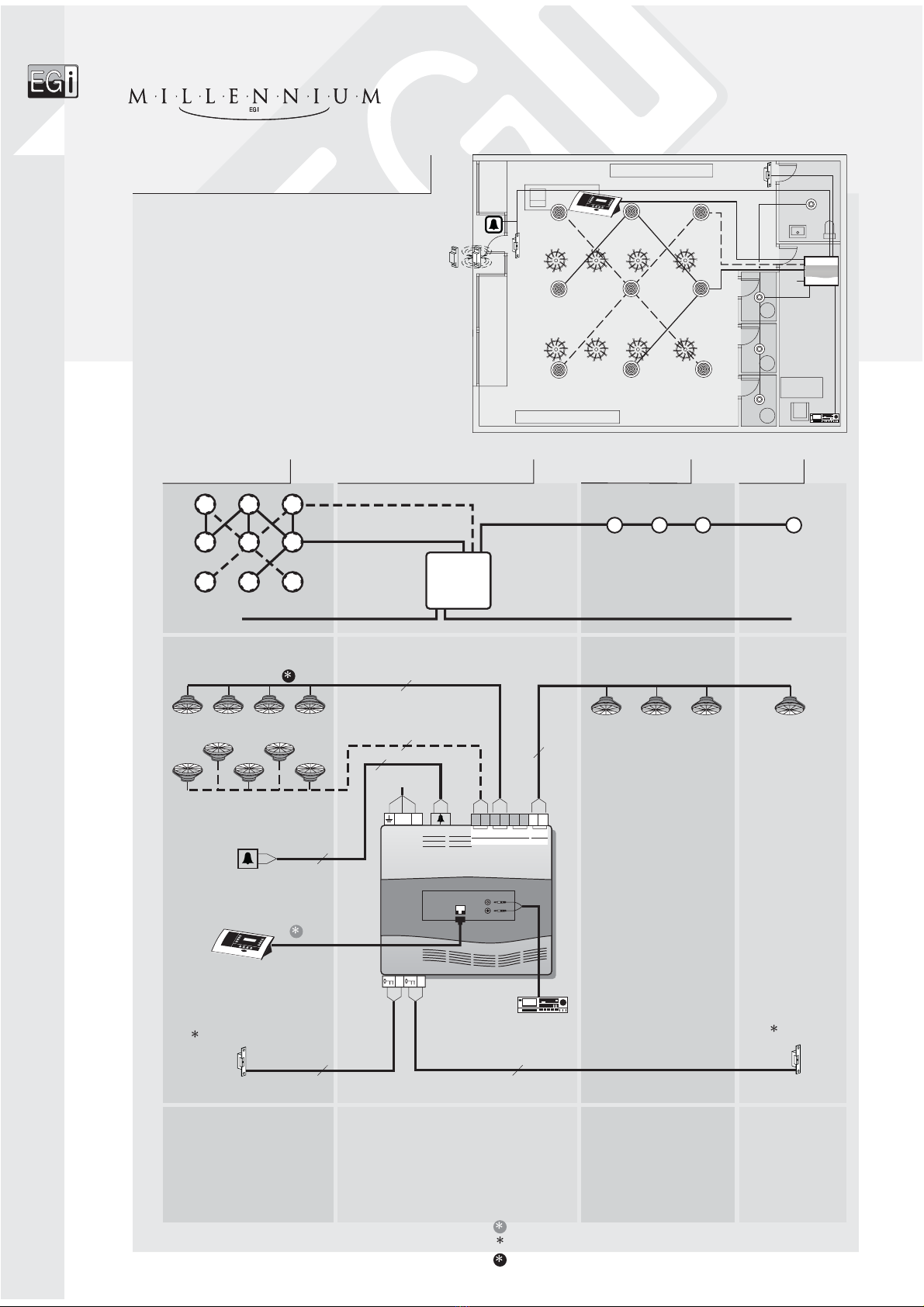
1 or 2 music channels.
Foo or ering to kitchen
through 4 microphones.
Music in restaurant.
Lock release in toilets.
General call.
Emergency evacuation.
Fast food restaurant
Installation example
Preinstallation
Installation
Materials
Cashiers
ZONE 1
Musical source
1 au io processor ______________1301.1
3 microphone bases_____________1105
3 volume regulators_____________1107
1 connection base for control
console/au io source __________1501
1 control console _______________1201.11
Stan ar box ø 60 mm
230 V~
1107
1105
G14A/16
G14A/16
1107
1105
1107
1105
1501
1301.x
CD
DINING ROOM
KITCHEN
CASHIERS
NOTE: See page 2 or urther in ormation about loudspeaker cable sections.
14
Use 1501 connection base or distances longer than the cable provided.
1201.11

0836
230 V~ 1301.x
1501
1107
1105
G14A/16
G14A/16
1107
1105
1107
1105
CD
10 W
V19A V19A
V19AV19A
2
2
1201.11
230 V~ 1301.x
1501
1107
1105
1107
1105
1107
1105
CD
1201.11
CASHIERS
DINING ROOM
KITCHEN
Fast food restaurant
Installation example
Dining room
Kitchen Toilets
La ies
Gentlemen
Gentlemen
La ies
5" fitting boxes = V19A - V29A
8" fitting boxes = V17B
Valid or any electric drive.
11 speakers 5" G14A/16
8" G12B/16
2 speakers ________G14A/16 2 speakers____________G14A/16
2 electric locks ________12 V~
15

1301
1301.1
241 9IN 5 IN
3IN
2IN
156 214
PIN
1PIN
2
CD
3 x 1 mm
2
1203
V19A V19A V19A
V19A
V19A
V19A
V19A
V19A
+ + + +
10W 10W 20W 10W
Z-2
1701
230 V~
230 V~
2
2OUT
1
4 4 EXT
ON1
OUT
2MIC
EXT
2
CD
0827
MAÎTRE
DINING ROOM 1
DINING ROOM 3
DINING ROOM 2
KITCHEN
BAR
Bar
Kitchen
S andard box ø 60 mm
Musical source
ZONE 1
1 or 2 music channels.
Separa e message broadcas o bar,
ki chen and dining rooms wi h chime.
Ex ernal music source inpu
for each dining room.
In ercom maî re-ki chen.
Emergency evacua ion.
Restaurant
Installation example
1 audio processor___________________1301.1
6 speakers ________________________G14A/32
1 in ercom uni ____________1203
2 speakers________________G14A/16
Preinstallation
Installation
Materials
16
10 W; 16 W
NOTE: See pa e 2 for further information about loudspeaker cable sections.
Use 1501 connection base for distances lon er than the cable provided.
230 V~
1201.1
1204
1105
1309.1
1204
1309.1
1105
1204
1203
1301.x
G14A/16
G14A/16
G14A/32
G14A/16
230 V~
G14A/16
1107
1105
1107
1309.1
1107
MAÎTRE
DINING ROOM 1
DINING ROOM 3
DINING ROOM 2
BAR
230 V~
1201.1
1204
1105
1309.1
1204
1309.1
1105
1204
G14A/16
G14A/16
230 V~
G14A/16
1107
1105
1107
1309.1
1107

24
165+/ +
V19A V19A
230
230 V ~
V~
1309.1
V19AV19A
24
1705
V19AV19AV19AV19A
1705
V19AV19AV19AV19A
1705
+ + +
20W 10W 10W
IN
3IN
2IN
1
1
2
4
5
6
1201.11
2
1204
OUT
+
24 MIC
OUT
24 MIC
IN
IN
OUT
0PIN 87651 909
24 MIC
OUT
1107 1105
CD
0827
20 W
17
1 con rol console ___________1201.11
3 amplifiers_______________1309.1
3 con rol uni s _____________1204
3 microphones bases ________1105
3 volume regula ors _________1107
10 speakers_______________G14A/16
This connection is only necessary if the installer wants the eneral line to be feedbacked with the surplus electric power from the amplifier.
DINING ROOM 3
SIMILAR TO DINING ROOM 2
2 speakers _____G14A/32
GENERAL LINE
DINING ROOM 2
GENERAL LINE
DINING ROOM 1
SIMILAR TO DINING ROOM 2
GENERAL LINE
S andard box ø 60 mm S andard box ø 60 mm
To 1201.11
Toilet
Dining romms
MAÎTRE
DINING ROOM 2
KITCHEN
DINING ROOM 1
DINING ROOM 3
BAR
Restaurant
Installation example
G14A/32
1301.x
1203
G14A/16
CD
MAÎTRE
KITCHEN
OOM 1
3
BAR
G14A/32
1301.x
1203
G14A/16
230 V~
1201.11
1204
1105
1309.1
1204
1309.1
1105
1204
G14A/16
G14A/16
230 V~
G14A/16
1107
1105
1107
1309.1
1107

1204
165
+/ +
230 V~
230 V ~
1309.1
24
IN
3IN
2IN
10PIN 87651 909
1201.11
1501
CD
V19A
V19A
V19A
V19A
V19A
V19A
1204
24
+ + +
20W 10W 10W
24
165+/ +
245 50 IN 90 10 19
1705
V19AV19AV19AV19A
1705
V19AV19AV19AV19A
V19AV19AV19AV19A
V19AV19AV19AV19A
2
20 W
1204
1204
1204
1204
1204
1501
1201.11
CD
1309.1
1309.1
1 connec ion base for con rol
console/audio source ____1501
1 con rol console_________1201.11
PRIVATE OFFICE 2. SAME AS PRIVATE OFFICE 1
PRIVATE OFFICE 3. SAME AS PRIVATE OFFICE 1
GENERAL
LINE
OFFICE 1
SAME CONNECTION
TO OFFICE 2
Office 1
1 amplifier ___________1309.1
1 con rol uni _________1204
8 speakers____________G14A/32
Office 2
1 amplifier ___________1309.1
1 con rol uni _________1204
8 speakers____________G14A/32
Materials Installation Preinstallation
S andard box ø 60 mm S andard box ø 60 mm S andard box ø 60 mm S andard box ø 60 mm
Private officesOffices 1 and 2 Reception
1 or 2 music channels.
Separa e message broadcas
o Plan 1, Plan 2 and Offices.
Middle size usiness
Installation example
PRIVATE OFFICE 1
OFFICE 1
OFFICE 2
PRIVATE
OFFICE
2
PRIVATE
OFFICE
3
TO LOWER FLOOR
PLANT 1
PRIVATE
OFFICE 1
RECEPTION
3 con rol uni s _________1204
6 speakers ___________G14A/32
GL
Musical source
18
NOTE: See pa e 2 for further information about loudspeaker cable sections.
Use 1501 connection base for distances lon er than the cable provided.
GENERAL LINE

1301
1301.1
241 9IN 5 IN
3IN
2IN
156 214
PIN
1PIN
2
230 V ~
1309.1
24
IN
3IN
2IN
10
PIN
87651 909
230 V ~
1309.1
24
IN
3IN
2IN
10
PIN
87651 909
+ + +
20W 10W 10W
+ + +
20W 10W 10W
230 V~
1701
1705 1705
+ + + +
10W 10W 20W 10W
Z-2
2
2
2
230 V~
230 V~
230 V~
1301.x
1309.1
TR7/8
TR7/8
1309.1
TR7/8
TO UPPER FLOOR
OFFICES
PLANT 1 PLANT 2
GL
Horn speakers Horn speakersHorn speakers
Plant 2
Plant 1
ZONE 1
4 horn speakers ________________TR7/8
2 amplifiers___________________1309.1
2 horn speakers ________________TR7/8
1 audio processor_______________1301.1
20 W
19

20
Millennium up to 127 message zones
The system can handle up to 127 message zones, selectable from the 1202 control console. They can also be grouped in up to 15 groups.
Depending on the features that we want for the system, there can be centralized areas and non-centralized areas. n area is said to be centralized when
its audio amplifier is inside the processor and non-centralized when its audio amplifier is in the area itself.
Product structure
In the next pages we can see several examples of this kind of systems.
CONTROL CONSOLE AUDIO PROCESSOR SERVICE MODULES
1315 Power supply unit.
1101.1 Modular RCA audio input with compressor for 2
audio programs.
1102.1 Modular digital FM tuner.
1103.1 Modular pre-recorded message player.
1104.10 Telephone messages module.
1303.1 2- one x 10 W amplifier.
1304.1 1- one 10 + 10 / 20W amplifier with digital control.
1305.1 Amplifier 1 one 40 W / 100 V with digital control.
1306.1 Adapter for 100 V power amplifiers with message
override relay.
1318 3- one relay module with message override.
1509 Module for audio signal selection.
1510 Converter module from general line to ribbon wire.
1308.1 Buffer-Power supply 15 V , 20 W. 230 V~.
1205.10 4-channel control unit, 1 W, 1-2 speakers. Message
override. White.
1205.12 4-channel control unit, 1 W, 1-2 speakers. Message
override. Black.
1307.1 Power supply unit 15 V ; 20 W; 230 V~.
1207.10 4-channel control unit, 2 W, 1-4 speakers. Message
override. White.
1207.12 4-channel control unit, 2 W, 1-4 speakers. Message
override. Black.
1206.10 Digital control keyboard. White.
1206.12 Digital control keyboard. Black.
1311 Digital 10 W amplifier. 15 V .
1310.1 Digital 20 W amplifier. 230 V~.
1105.10 Pre-amplified XLR microphone base. White.
1105.12 Pre-amplified XLR microphone base. Black.
1107.10 Volume regulator for 1105 base. White.
1107.12 Volume regulator for 1105 base. Black.
1106.10 Volume regulator and auxiliary input. White.
1106.12 Volume regulator and auxiliary input. Black.
1202 Control console.
1501.10 Connection base for control console/audio
source. White.
1501.12 Connection base for control console/audio
source. Black.
1316 Central audio processing unit.
CENTRAL PROCESSOR ACCESSOIRES AND MISCELLANEOUS MODULES
1707 Chassis for 19" rack (84 UP; 3 UA).
1709 Tabletop cabinet (84 UP; 3 UA).
1710 Blind cover (7 UP).
These de ices need to be configured as a zone in the system during the SETUP process
(max. 126 digital zones).
Other manuals for Millennium
1
Table of contents
Other EGi Conference System manuals

Popular Conference System manuals by other brands

Vokkero
Vokkero VARSITY II user guide

Sony
Sony Ipels PCS-G50 operating instructions

Lars Thrane
Lars Thrane LT-3100 User & installation manual

Nortel
Nortel Agent Greeting 2.0 Maintenance and troubleshooting guide

Steelcase
Steelcase RoomWizard Retrofit Installation Instructions

Bose
Bose VIDEOBAR VB-S manual


