manuals.online logo
Brands
  1. Home
  2. •
  3. Brands
  4. •
  5. CoachComm
  6. •
  7. Conference System
  8. •
  9. CoachComm X-System User manual

CoachComm X-System User manual

Fax 1.888.329.2658
Game Day Guide
Getting Started
This Game Day Guide is a basic reference for setting up your X-System. For complete operation instructions, see the
X-System Operating Manual, which is available on CoachComm’s website at: www.coachcomm.com/x-system-ata-support/.
CAUTION: Allow only responsible, authorized individuals who have read all of the instructions and warnings to set up and
operate your X-System.
Required Power Connection:
• Minimum of one dedicated 15A 120VAC circuit
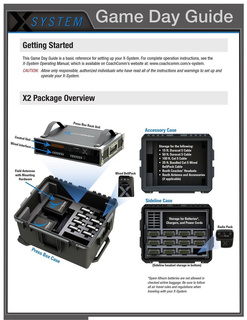
X-System ATA Package Overview
WAM
PS-4001
Power Supplies
WIM
Uninterruptible
Power Supply
Uninterruptible
Power Supply
Radio Pack
Drawer
Control Units
Touch Screen
Monitor
RT Bracket
Mast
RT Cable
Pull-Out PC
Keyboard
Radio Pack Drawer
5-Bay Battery
Chargers
(PC in Rear) (Patch Panel, AC Power Outlet,
and Storage of Mast Mounting Plates in Rear)
Monitor Trunk
Mast and RT Case
X-System Wireless Trunk
Accessory Storage
(USB pairing cables,
extra beltclips,
USB drive,
spare antennas)
Game Day Guide
Prepare RT mast.
1a. Position the X-System Wireless Trunk and the Monitor
Trunk side by side at mideld.
1b. Connect the trunks using the two mast mounting
plates.
Note: CoachComm recommends connecting the trunks on a
at surface as close to mideld as possible. After
connecting the trunks, they can be rolled to their nal
position.
Mast Mounting Plate
Top Mounting Plate with Mast Secured
Position trunks.
12
The procedures in this step are referenced in the gure
below and may require at least two people.
2a. Remove the mast from its storage case and insert it
into the hole of the mounting plates.
2b. Secure the RT mounting bracket to the top of the
mast using the provided pin.
2c. Connect the RT cable to the rst RT on the
bracket.
2d. Attach the cable’s strain relief to the eye bolt on the
mounting bracket.
2e. Align the mast so the RT mounting bracket is parallel
to the sideline, and secure the mast by tightening the
knob on top of the mounting plate.
Note: Be sure not to overtighten the knob. Use just
enough pressure to secure the mast.
2f. Bend the antennas so there is a 90° angle between
the antenna and the RT and point their tips toward the
opposing team’s RT mast.
2g. Fully extend the mast, beginning with the top section
and locking each section in place as you go.
Top Mounting Plate and
knob to secure mast
Bottom Mounting Plate
90
Align mast so RT bracket is parallel to the sideline.
Game Day Guide
Set Home/Away status.
5
(4b.) PC LAN port
5a. Follow the prompts on your top (primary) CU to set your
system’s Home/Away status.
Important: No RF transmission will occur until the Home/Away
status is selected. Failure to set this status properly
may result in RF interference.
The Home/Away setting aids customers with hopping
pattern coordination between RTs and Radio Packs.
Based on this setting, all of the RTs on the system will
be assigned specic hopping patterns by the Control
Unit (CU). It is very important to set this status correctly.
Hopping pattern coordination improves operation between
X-Systems.
During startup, the conguration le (CCF) will begin
loading while the Home/Away prompt is displayed on the
top CU. A progress bar shows the load process on the
bottom CU. Once the Home/Away prompt is cleared, the
CCF load progress can be seen on both CUs.
Connect LAN and AC power, then power on the system.
4a. Route the LAN cable and UPS power cable from the Monitor Trunk to the the X-System Wireless Trunk
using the trunks’ rear cable hatches.
4b. Connect the LAN cable to the PC LAN port on the X-System Wireless Trunk’s rear patch panel.
4c. Connect the UPS power cable to the X-System Wireless Trunk’s AC outlet box.
4d. Route an external power extension cord into the X-System Wireless Trunk’s rear cable hatch and
connect it to the main AC power cord from the AC outlet box.
CAUTION: Secure and protect any cords to prevent walkway hazards and potential contact with moisture.
4e. Power on both trunks’ UPS power buttons.
4
Connect RT cable and dry pair to the patch panel.*
3a. Connect the RT cable to the “X-NET Top RT Set” port on the X-System Wireless Trunk’s rear patch panel.
3b. Connect stadium’s dry pair panel to the corresponding “STADIUM DRY PAIR” ports on the rear patch panel.
(You can nd additional instructions about dry pair connections in the X-System Operating Manual found at
www.coachcomm.com/x-system-support.)
*Fiber connections not shown here. For more information about ber, refer to the Wireless Press Box Game Day Guide or X-System Operating Manual.
3
(3a.) Connect
RT cable to rear
patch panel.
(3b.) Connect dry
pairs to rear
patch panel.
5b. Wait until the CU(s) display the “CCF Loaded” message along
with a conguration le summary. (The bottom CU will take
about 30 seconds longer than the top.) When the CCF load
is complete, the home screen will display on the front of the
CU(s) and you can proceed.
5c. Open X-Ware on the touch screen monitor and allow its Home
screen to load.
Game Day Guide
205 Technology Parkway
Auburn, Alabama 36830
www.coachcomm.com
Phone 1.800.749.2761
Fax 1.888.329.2658
While CoachComm makes every attempt to maintain the accuracy of the information contained in this document, this information is subject to change without notice.
Please check our website for the latest system specications and certications. Copyright © 2018–2020 CoachComm LLC. All rights reserved. The X-System logo is a
trademark of CoachComm LLC. All other trademarks are property of their respective owners. Document Reference: 2020.06 D0000393_C
The procedures in this step should be performed with at least two people.
7a. Install a fully charged Lithium-Polymer rechargeable battery or three AA alkaline
batteries in each Radio Pack (RP).
7b. Power on the rst two RPs by pressing and holding the Power button on the
back of the RP for 3 seconds.
7c. Conrm each RP is on the same conference, connect a headset to each RP, and
conduct a walk test to conrm their operation. The RP’s LQ value can be used to
gauge performance. See the X-System Operating Manual for more information
about LQ values.
Important: Each tester should walk their RPs to opposite goal lines and back, ensuring
clear communication between all RPs. Always place the RP on the hip
opposite from the press box when walk testing.
7d. After walk testing is complete, place the RP down on a table or bench. Be sure
to place each RP a foot or so apart; bunching RPs together could impact wireless
performance. Repeat steps 7b-7c for each of the remaining RPs.
Important: If raining, cover the RPs or return them to their drawer.
7e. Conrm communication between wireless and wired coaches.
Once your event has ended, power off and properly stow
away all X-System components:
8a. Power off all RPs and stow them in their drawers.
8b. CoachComm recommends saving a backup copy of
your system conguration le to the PC desktop or a
USB drive. Then, close X-Ware and shut down the
PC.
Power on and walk test Radio Packs.
7
Power off and stow away X-System.
6Set up Press Box Unit and null system.
The procedures in this step should be performed with at least two people.
6a. Once the sideline trunks are congured, set up and connect power to the Press Box Unit. Have someone stay with
the sideline trunks to assist in the verication of dry pairs during this step.
6b. Connect dry pair panel in the Press Box to the corresponding ports on the rear of the WIM in the Press Box Unit.
6c. Connect wired BeltPacks and cables for each coach. Make sure all TALK buttons are off.
6d. Auto-null all of the lines from the sideline using X-Ware’s Conference view (under the System Settings menu). If there
is noticeable echo on some channels of the wireless components, conrm that all TALK buttons are off and repeat the
auto-null step.
(7b.) Turn on by
holding Power button
for 3 seconds.
(7a.) Install battery.
8
8c. Power off the CU(s), then power off both trunks’ UPS
power buttons. Unplug and remove your extension cord,
LAN cable, and UPS power cable.
8d. Carefully lower and disassemble the RT mast and
RT mounting bracket(s),stowing them in their assigned
sections of the accessory case.
8e. Disconnect the mast mounting plates and separate the
two sideline trunks. Close and secure their lids.
Important: Thoroughly dry off any moisture prior to storage.
Other manuals for X-System

2

Other CoachComm Conference System manuals

CoachComm X-System User manual

CoachComm

CoachComm X-System User manual

CoachComm X-System User manual

CoachComm

CoachComm X-System User manual

CoachComm Tempest NG900 User manual

CoachComm

CoachComm Tempest NG900 User manual

CoachComm X SYSTEM Service manual

CoachComm

CoachComm X SYSTEM Service manual

CoachComm X System WPB2 User manual

CoachComm

CoachComm X System WPB2 User manual

CoachComm eVenue Tempo User manual

CoachComm

CoachComm eVenue Tempo User manual

CoachComm Tempo Go User manual

CoachComm

CoachComm Tempo Go User manual

CoachComm X2 User manual

CoachComm

CoachComm X2 User manual

CoachComm Tempest User manual

CoachComm

CoachComm Tempest User manual

CoachComm Tempest NG User manual

CoachComm

CoachComm Tempest NG User manual

CoachComm X2 Installation and user guide

CoachComm

CoachComm X2 Installation and user guide

CoachComm tempest fx User manual

CoachComm

CoachComm tempest fx User manual

CoachComm X System WPB1 User manual

CoachComm

CoachComm X System WPB1 User manual

CoachComm X SYSTEM User manual

CoachComm

CoachComm X SYSTEM User manual

Popular Conference System manuals by other brands

Teldat Bintec Elmeg DECT150 Setup

Teldat

Teldat Bintec Elmeg DECT150 Setup

Crestron UC-B31-T-WM quick start guide

Crestron

Crestron UC-B31-T-WM quick start guide

Cisco TelePresence DX70 Setting up for care home use

Cisco

Cisco TelePresence DX70 Setting up for care home use

Polycom SIP 3.1 Administrator's guide

Polycom

Polycom SIP 3.1 Administrator's guide

RADVision Scopia XT1000 user guide

RADVision

RADVision Scopia XT1000 user guide

ADTRAN NetVanta 7100 Configuration guide

ADTRAN

ADTRAN NetVanta 7100 Configuration guide

Actia ACU6 user manual

Actia

Actia ACU6 user manual

TANDBERG 2000 MXP user guide

TANDBERG

TANDBERG 2000 MXP user guide

Polycom ReadiRecorder brochure

Polycom

Polycom ReadiRecorder brochure

Xantrex GT Series Three Phase Ethernet Communications... installation guide

Xantrex

Xantrex GT Series Three Phase Ethernet Communications... installation guide

Cisco EX60 user guide

Cisco

Cisco EX60 user guide

Elastix ELX-3000 Assembly guide

Elastix

Elastix ELX-3000 Assembly guide

Sony SX-1070A Instructions for use

Sony

Sony SX-1070A Instructions for use

Lexicomm ViLX-228 Installation and commissioning manual

Lexicomm

Lexicomm ViLX-228 Installation and commissioning manual

GeoDesy FSO GigaPico Next AutoFocus user manual

GeoDesy FSO

GeoDesy FSO GigaPico Next AutoFocus user manual

Aethra SUPERNOVA X150 Technical specifications

Aethra

Aethra SUPERNOVA X150 Technical specifications

RADVision Scopia XT5000 Series Quick setup guide

RADVision

RADVision Scopia XT5000 Series Quick setup guide

Siemens Mobile MC35i Terminal AT Command set

Siemens Mobile

Siemens Mobile MC35i Terminal AT Command set

manuals.online logo
manuals.online logoBrands
  • About & Mission
  • Contact us
  • Privacy Policy
  • Terms and Conditions

Copyright 2025 Manuals.Online. All Rights Reserved.