Eglo TIROL User manual

Ceiling Fan Owner's Manual
Read and Save These Instructions
MODEL: TIROL

Tools and Materials Required.........................................................................................
Unpacking Your Fan ......................................................................................................
Safety Rules...................................................................................................................
Mounting Options...........................................................................................................
Hanging the Fan ............................................................................................................
Making Electrical Connections.......................................................................................
Finishing the Installation.................................................................................................
Attaching the Fan Blades...............................................................................................
Operating Your Fan .....................................................................................................
Care of Your Fan...........................................................................................................
Troubleshooting............................................................................................................
TABLE OF CONTENTS
1
1
2
3
4-5
6
7
8
9
10
10
Install the Light Kit .........................................................................................................8

1
a
c
d
e
f
g
2. PACKAGE CONTENTS
Unpack your fan and check the contents. You
should have the following items:
a. Blade set
b. Hanger bracket
c. Canopy and Cover
d. Downrod assembly
e. Coupling cover
f. Fan motor assembly
h.
Philips screw driver
Blade screw driver
11 mm wrench
Step ladder
Wire cutters
1. TOOLS AND MATERIALS
REQUIRED
h
g. Lamp shade (for with light model)
Down cover (for no light model)
3) Remote Control (1)
3
10
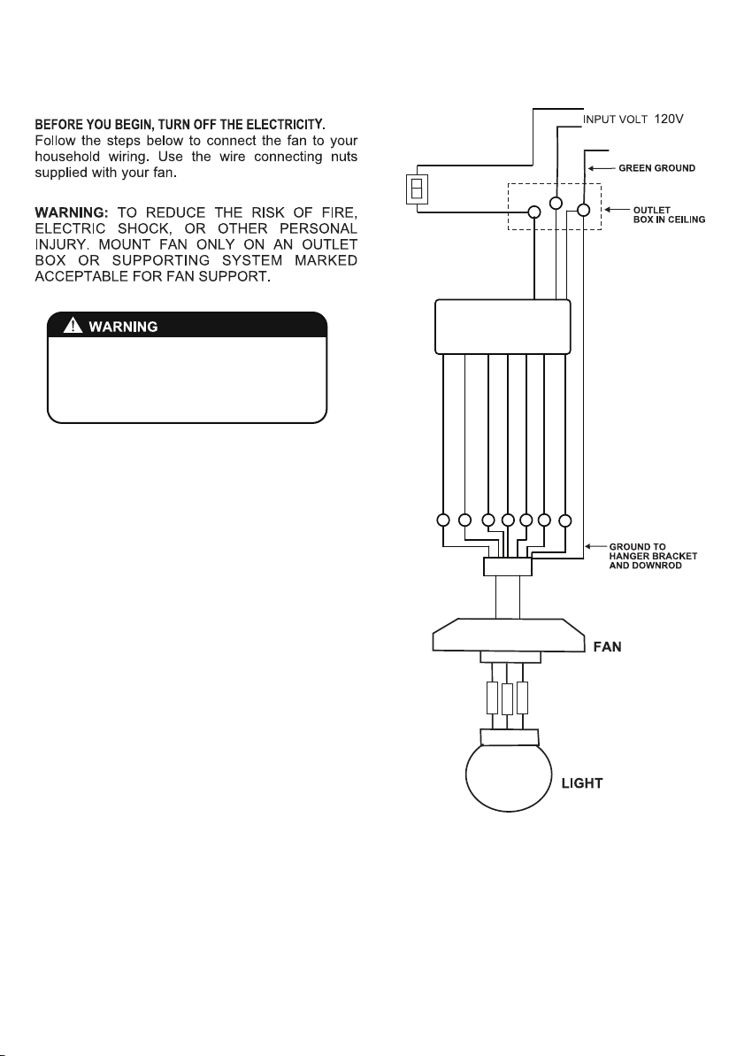
1. To reduce the risk of electric shock, insure
electricity has been turned off at the circuit
breaker or fuse box before beginning.
2. All wiring must be in accordance with the
National Electrical Code and local electrical
codes. Electrical installation should be
performed by a qualified licensed electrician.
3. WARNING: To reduce the risk of electrical
shock and fire, do not use this fan with any
solid-state fan speed control device.
4. WARNING: To reduce the risk of personal
injury, use only the two steel screws (and lock
washers) provided with the outlet box for
mounting to the outlet box. Most outlet boxes
commonly used for the support of lighting
fixtures are not acceptable for fan support and
may need to be replaced, consult a qualified
electrician if in doubt.
5. The outlet box and support structure must be
securely mounted and capable of reliably
supporting a minimum of 50 pounds. Use only
UL Listed outlet boxes marked "FOR FAN
SUPPORT".
6. The fan must be mounted with a minimum of 7
feet clearance from the trailing edge of the
blades to the floor.
7. Do not operate reversing switch while fan
blades are in motion. Fan must be turned off
and blades stopped before reversing blade
direction.
8. Avoid placing objects in the path of the blades.
9. To avoid personal injury or damage to the fan
and other items, be cautious when working
around or cleaning the fan.
10. Do not use water or detergents when cleaning
the fan or fan blades. A dry dust cloth or
lightly dampened cloth will be suitable for most
cleaning.
11. After marking electrical connections, spliced
conductors should be turned upward and
pushed carefully up into outlet box. The wires
should be spread apart with the grounded
conductor and the equipment-grounding
conductor on one side of the outlet box.
12. Electrical diagrams are reference only. Light kit
that are not packed with the fan must be UL
Listed and marked suitable for use with the
model fan you are installing. Switches must be
UL General Use Switches. Refer to the
Instructions packaged with the light kits and
switches for proper assembly.
2
3. SAFETY RULES
WARNING
TO REDUCE THE RISK OF FIRE, ELECTRIC
SHOCK OR PERSONAL INJURY, MOUNT
FAN TO OUTLET BOX MARKED
"ACCEPTABLE FOR FAN SUPPORT".
WARNING
TO REDUCE THE RISK OF PERSONAL
INJURY, DO NOT BEND THE BLADE
BRACKETS (ALSO REFERRED TO AS
FLANGES) DURING ASSEMBLY OR AFTER
INSTALLATION. DO NOT INSERT OBJECTS IN
THE PATH OF THE BLADES.
3
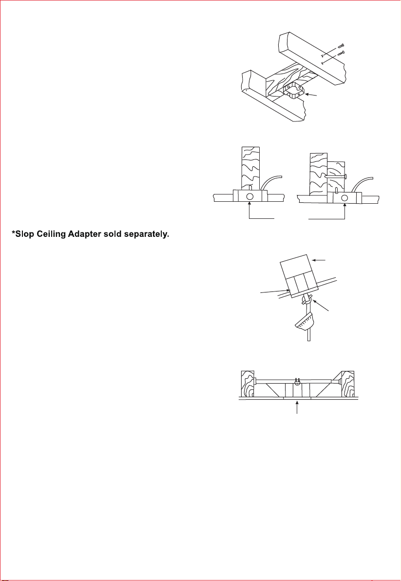
4. MOUNTING OPTIONS
If there isn't an existing UL listed mounting box,
then read the following instructions. Disconnect the
power by removing fuses or turning off circuit
breakers.
Secure the outlet box directly to the building
structure. Use appropriate fasteners and building
materials. The outlet box and its support must be
able to fully support the moving weight of the fan
(at least 50 lbs). Do not use plastic outlet boxes.
Figures 1,2 and 3 are examples of different ways to
mount the outlet box.
Note: You may need a longer downrod to maintain
proper blade clearance when installing on a steep,
sloped ceiling. (Fig. 3)
To hang your fan where there is an existing fixture
but no ceiling joist, you may need an installation
hanger bar as shown in Figure 4.
Outlet box
Outlet box
Figure 1
Figure 3
Figure 4
Outlet box
Figure 2
Provide strong
support
Recessed
outlet box
Ceiling
mounting
bracket
Angled ceiling
maximum 20º

4
5. HANGING THE FAN
REMEMBER to turn off the power. Follow the steps
below to hang your fan properly.
STANDARD CEILING INSTALLATION
Step 1. Pass the 120-volt supply wires through the
center hole in the ceiling hanger bracket as shown in
Fig. 5.
Step 2. Secure the hanger bracket to the ceiling
outlet box with the screws and washers included
with mounting hardware (Fig.5).
Step 3. Remove the hanger pin, lock pin and set
screws from the top of the motor assembly.
Step 4. Route wires exiting from the top of the fan
motor through the canopy, coupling cover and then
through the ball/downrod. (Fig. 6)
Step 5. Align the holes at the bottom of the downrod
with the holes in the collar on top of the motor
housing. Carefully insert the hitch pin through the
holes in the collar and downrod. Be careful not to
jam the pin against the wiring inside the downrod.
Insert the locking pin through the hole near the end
of the hitch pin until it snaps into its locked position.
(Fig. 6)
Step 6. Tighten two set screws on top of the fan
motor firmly.
Step 7. Place the downrod ball into the hanger
bracket socket. This will allow you to make the
electrical connections. (Fig. 7)
Figure 6
Downrod
Canopy
Set screws
Hitch
pin
Lock
pin
Figure 7
Registration slot
Coupling cover
5
MAKING ELECTRICAL CONNECTIONS
Fig. 11
RECEIVER
TO MOTOR(PINK)
TO MOTOR(GREY)
TO MOTOR(RED)
FOR LIGHT (BLUE)
FOR
LIGHT
(RED)
BLACK
WHITE
YELLOW/GREEN
BLACK(TO MOTOR)
BLACK(TO AC L)
POWER
CONTROL
(Fig.11)
DO NOT USE THIS DC MOTOR FAN IN
CONJUNCTION WITH ANY VARIABLE
(RHEOSTAT) WALL CONTROL OR
REMOTE CONTROL.
FOR LIGHT (BROWN)
YELLOW/GREEN YELLOW/GREEN
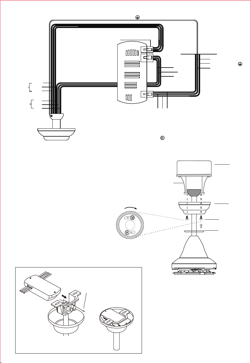
House Supply Wires
Black(L)
Yellow/Green(E)
White(N)
Black(L)
White(N)
Yellow/Green(E)
Grey
Pink
Red
Grey
Pink
Red
Brown
Blue
Red
Light connector
Yellow/Green(E)
Motor wire
Light wire
x2
VIEW AFTER INSTALLATION
RF ANT
RECEIVER
7. Canopy Assembly
After connecting the wires,
place the DC fan driver in hanger bracket
as shown, turn the leads upward and
separate wire connections and put
neatly inside of the outlet box.
Locate the two screws on the underside
of the hanger bracket.
Attach the canopy to the hanger bracket
by placing the screws into the slot in the
canopy, then twist clockwise to lock it
into place, and tighten the screws firmly.
Twist clockwise the canopy cover to the canopy.
Outlet Box
Canopy
Screws
Hanger Bracket
Canopy Cover
Figure 12

6
Figure 13
9. INSTALL LIGHT KIT
Step 1. Twist the lamp shade onto the light plate till sung.
(Fig.14)
Figure 14
Step 1. Fasten each blade to motor by using
three screws.
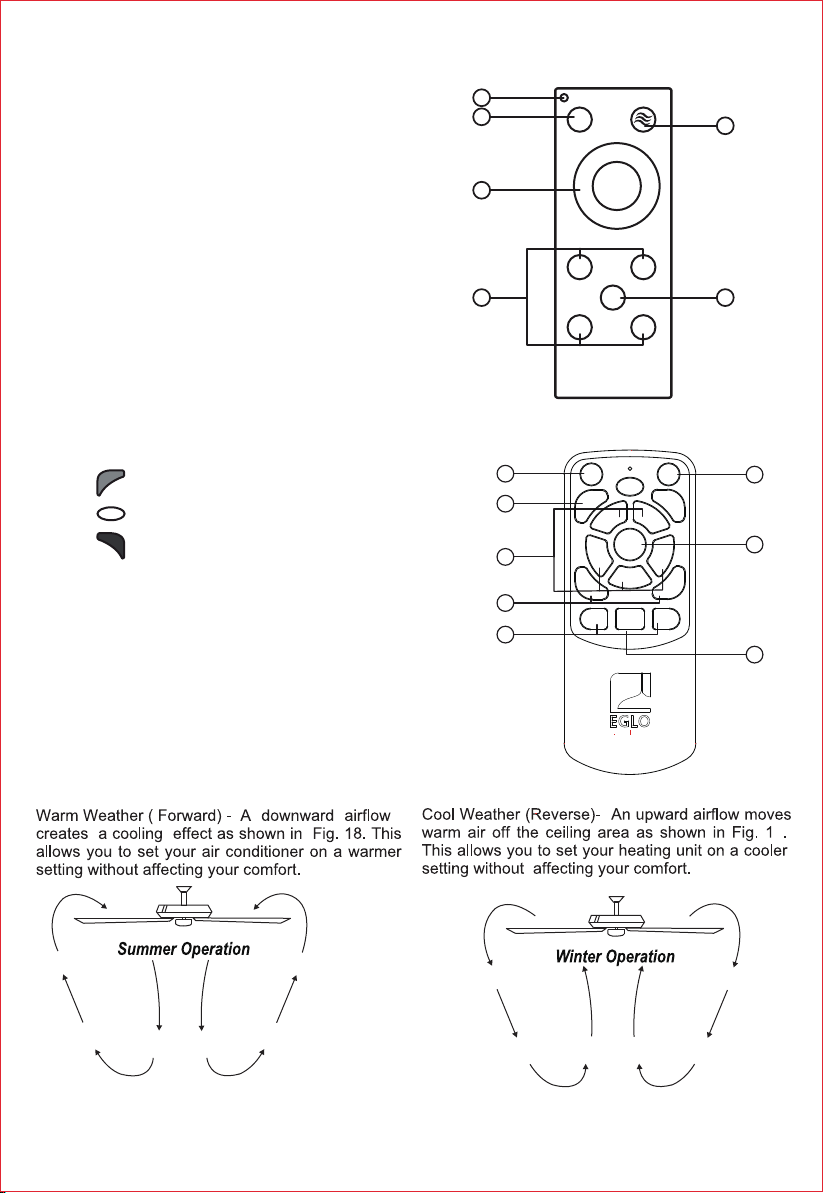
Figure 18 Figure 19
7
10. OPERATING YOUR FAN
9
1. LED Indicator Light
2. Turns fan OFF
3. Fan Speed & ON:
1 Lowest Speed
2 Low Speed
3 Medium Speed
4 High Speed
5 Highest Speed
4. Timer:
1H - Fan turns off after 1 Hour
2H - Fan turns off after 2 Hours
4H - Fan turns off after 4 Hours
8H - Fan turns off after 8 Hours
5. Forward / Reverse
6. Natural Wind
FAN
OFF
1
3
524
1H 2H
F/R
4H 8H
1
6
2
3
45
1. Turns fan OFF
2. Colour Temperature:
Warm White
Neutral White
Cool White
3. Fan Speed & ON:
1 Lowest Speed
2 Low Speed
3 Medium Speed
4 High Speed
5 Highest Speed
4. Increase Brightness (+)/ Decrease Brightness (-)
5. Timer:
2H - Fan turns off after 2 Hours
8H - Fan turns off after 8 Hours
6. Turns light ON & OFF
7. Forward / Reverse
8. Natural Breeze
6
8
7
1
2
3
4
5
8H
2H
+
LED
-
LED
F/R
5
4
3
2
1
LIGHT
ON/OFF
FAN
OFF
NATURAL
BREEZE
my light my style

8
12. TROUBLESHOOTING
11. CARE OF YOUR FAN
Here are some suggestions to help you maintain your fan
1. Because of the fan's natural movement, some connections may become loose. Check the support
connections, brackets, and blade attachments twice a year. Make sure they are secure. (It is not
necessary to remove fan from ceiling.)
2. Clean your fan periodically to help maintain its new appearance over the years. Use only a soft brush or
lint-free cloth to avoid scratching the finish. The plating is sealed with a lacquer to minimize discoloration
or tarnishing. Do not use water when cleaning. This could damage the motor, or the wood, or possibly
cause an electrical shock.
3. You can apply a light coat of furniture polish to the wood blades for additional protection and enhanced
beauty. Cover small scratches with a light application of shoe polish.
4. There is no need to oil your fan. The motor has permanently lubricated bearings.
IMPORTANT: MAKE SURE THE POWER IS OFF AT THE ELECTRICAL PANEL BOX BEFORE YOU
ATTEMPT ANY REPAIRS. REFER TO THE SECTION "MAKING ELECTRICAL CONNECTIONS".
Problem
Fan will not start.
Fan sounds noisy.
Solution
1. Check circuit fuses or breakers.
2. Check line wire connections to the fan and switch wire connections in the switch
housing.
CAUTION: Make sure main power is off.
1. Make sure all motor housing screws are snug.
2. Make sure the screws that attach the fan blade bracket to the motor hub is tight.
3. Make sure wire nut connections are not rubbing against each other or the interior
wall of the switch housing.
CAUTION: Make sure main power is off.
4. Allow a 24-hour "breaking-in" period. Most noise associated with a new fan
disappear during this time.
5. If using an optional light kit, make sure the screws securing the glassware are tight.
Check that light bulb is also secure.
6. Some fan motors are sensitive to signals from solid-state variable speed controls.
If you have installed this type of control, choose and install another type of control.
7. Make sure the upper canopy is a short distance from the ceiling. It should not
touch the ceiling.
Table of contents
Other Eglo Fan manuals

Eglo
Eglo TIGGANO 35181 User manual

Eglo
Eglo SURF 20549701 User manual

Eglo
Eglo TOURBILLION User manual

Eglo
Eglo STRADBROKE User manual

Eglo
Eglo BONDI Series User manual

Eglo
Eglo MOSTEIROS 35004 User manual

Eglo
Eglo BONDI 1 User manual

Eglo
Eglo SEACLIFF 20523401 Instruction Manual

Eglo
Eglo Casou User manual

Eglo
Eglo Whitehaven 203229A User manual

Eglo
Eglo NOOSA Series User manual

Eglo
Eglo 40 Degree Canopy User manual

Eglo
Eglo NEVIS 202748 User manual

Eglo
Eglo TIGGANO 35039 User manual

Eglo
Eglo HOI AN 35027 User manual

Eglo
Eglo TORQUAY User manual

Eglo
Eglo 203227A User manual

Eglo
Eglo NEVIS-II User manual

Eglo
Eglo GELSINA User manual

Eglo
Eglo SUSALE User manual


