manuals.online logo
Brands
  1. Home
  2. •
  3. Brands
  4. •
  5. Greenheck
  6. •
  7. Fan
  8. •
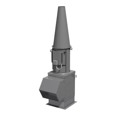
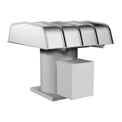
  9. Greenheck CUBE-098 Installation guide

Greenheck CUBE-098 Installation guide

®
Upon receiving unit, check for any damage
and report it immediately to the shipper. Also
check to see that all accessory items are
accounted for.
Move fan to desired location and fasten
securely through mounting holes in base.
Shims may be necessary depending upon
roofing material thickness. The diagram
below shows dimensions for Model CUBE.
Access to the motor compartment is
accomplished by removing the screws
designated “R” in Fig. 1. The cover can then
be removed and placed on a flat surface in
an area protected from strong winds.
The motor’s amperage and voltage rating
must be checked for compatibility to the
supply voltage prior to final electrical
connection. For NFPA - restaurant CUBE
applications, the electrical supply must enter
the motor compartment through the breather
tube. For other non-flammable applications
the electrical supply can be routed through
the conduit chase between the curb cap and
the bottom of the motor compartment.
Consult local code authorities for your
specific requirements.
A drain trough is provided on all CUBE fans
for single-point drainage of water and
residue. Some means for collection of this
residue must be provided, either a container
directly under the trough or use of an
adapter and pipe to carry the residue to a
remote collection point. An optional grease
trap with water separator baffles is available
from your Greenheck representative.
Installation, Operating and Maintenance Manual
READ AND SAVE THESE INSTRUCTIONS
Model CUBE Belt Drive
Upblast Centrifugal
Roof Exhaust Fan
PN 457693
MODEL A B *C D Shaft
Bearings
Damper
Size
Roof
Opening
Approx.
Unit
Weight
CUBE-098, 101, 101HP, 121, 131 19 247/8281/4173/83/412x12 141/2x 141/266
CUBE-141, 141HP
CUBE-161, 161HP, 161XP 22 287/8293/4193/83/416x16 181/2x 181/287
CUBE-180 3/4
CUBE-180HP 1 126
CUBE-200 30 353/8285/821 3/4
18x18 201/2x 201/2
CUBE-200HP 1 142
CUBE-220, 220HP
CUBE-240, 240HP, 240XP 34 423/4337/8251/21 24x24 261/2x 261/2175
CUBE-300, 300HP, 300XP 40 50 36 29 1 30x30 321/2x 321/2313
CUBE-360, 360HP, 360XP 46 585/8391/8293/836x36 381/2x 381/2440
CUBE-420 52 653/16 443/4351/4
11/442x42 441/2x 441/2578
CUBE-480 58 743/16 481/836 11/248x48 501/2x 501/2675
Dimension “A” is the inside dimension of the curb cap. The roof curb should be 11/2in. less than
the curb cap to allow for roofing and flashing.
All dimensions are in inches. *May vary depending on motor size.
Dimensional Data
B
R
13/4 in.
A
D*C
Fig. 1
Installations
Recommended
General
Ventilation
Installation
Recommended
Commerical
Kitchen
Installation
8 in. or 12 in. min.
Recommended
Roof Opening
3/4 in.
11/4 in. 11/4 in.
Recommended
Duct and
Damper Size
Wiring by
Others
Factory Wired
Motor to
Disconnect
Roof Deck
Damper
Welded Duct
by others
min. of 18 in.
above roof
deck (per
NFPA)
NEMA 3R
Disconnect
factory wired
from motor to
disconnect
through the
breather tube
Liquid Tight
Flexible Conduit
by Others
Recommended
Roof Opening
Roof Deck
Minimum 40 in.
Discharge
Height
8 in. min.
Grease
Trap
Vented Curb
Extension
Optional
(per NFPA)
WHEEL
ROTATION
All CUBE fans
have CW wheel
rotation when
viewed from top
of fan.
WHEEL
OVERLAP
DIMENSIONS
G
Fig. 2 Fig. 3
Fig. 4
Fig. 6
Fig. 5
Cl
o
c
k
w
i
s
e
Direction of wheel rotation is critical. Reversed rotation will result in poor air performance, motor overloading and possible
burnout. Check wheel rotation (viewing from the shaft side) by momentarily energizing the unit. Rotation should be clockwise
as shown in Fig. 3 and correspond to the rotation decal on the unit.
If adjustments are made, it is very important to check the pulleys for proper alignment. Misaligned pulleys lead to excessive
belt wear, vibration, noise and power loss. (See Fig. 4 )
For all CUBE units belt tension can be adjusted by loosening four fasteners (marked “R”) on the drive frame. The motor plate
slides on the slotted adjusting arms and drive frame angles in the same manner (see Fig. 5). Belt tension should be adjusted
to allow 1/64 inch of deflection per inch of belt span. For example, a 15 inch belt span should have 15/64 inch (or about 1/4
inch) of deflection with moderate thumb pressure at mid-point between pulleys. (See Fig. 6). Overtightening will cause
excessive bearing wear and noise. Too little tension will cause slippage at startup and uneven wear.
The adjustable motor pulley is factory set for the RPM specified. Speed can be increased by closing or decreased by opening
the adjustable motor sheave. Two groove variable pitch pulleys must be adjusted an equal number of turns open or closed.
Any increase in speed represents a substantial increase in the horsepower required by a unit. Motor amperage should always
be checked to avoid serious damage to the motor when speed is varied.
CORRECT WRONG WRONG WRONG
Belt Span
Deflection = Belt Span
64
NOTE:
Identical fasteners
on opposing side
R
2
Pre-Starting Checks
Check all fasteners for tightness. The wheel should rotate freely and be aligned as shown in Fig. 2. Wheel position is preset
and the unit is test run at the factory. Movement may occur during shipment, and realignment may be necessary. Centering
can be accomplished by loosening the bolts holding the drive frame to the shock mounts and repositioning the drive frame.
Wheel and inlet cone overlap can be adjusted by loosening the set screws in the wheel and moving the wheel to the desired
position.
MODEL G
098-161 1/4 in.
180-300 1/2 in.
360-480 3/4 in.
3
MAINTENANCE
Belts tend to stretch after a period of time. They should be checked periodically for wear and tightness. When replacing
belts, use the same type as supplied with the unit. Matched belts should always be used on units with multigroove pulleys.
For belt replacement, loosen the tensioning device far enough to allow removal of the belt by hand. Do not force belts on or
off. This may cause cords to break, leading to premature belt failure. Once installed, adjust belts as shown in “Pre-Starting
Checks.”
Shaft bearings can be classified in two groups: relubricating and non-relubricating. All bearings on standard Model CUBE
fans are factory lubricated and require no further lubrication under normal use (between -20°F and 180°F in a relatively clean
environment). Units installed in hot, humid or dirty locations should be equipped with special bearings. These bearings will
require frequent lubrication. Caution should be employed to prevent overpacking or contamination. Grease fittings should be
wiped clean. The unit should be in operation while lubricating. Extreme care should be used around moving parts. Grease
should be pumped in very slowly until a slight bead forms around the seal. A high grade lithium base grease is
recommended.
Motor maintenance is generally limited to cleaning and lubrication (where applicable). Cleaning should be limited to exterior
surfaces only. Removing dust buildup on motor housing ensures proper motor cooling. Greasing of motors is only intended
when fittings are provided. Many fractional motors are permanently lubricated and should not be lubricated further. Motors
supplied with grease fittings should be greased in accordance with manufacturers’ recommendations. Where motor
temperatures do not exceed 104°F (40°C), the grease should be replaced after 2000 hours of running time as a general rule.
Wheels require very little attention when moving clean air. Occasionally, oil and dust may accumulate causing imbalance.
When this occurs, the wheel and housing should be cleaned to ensure smooth and safe operation.
The unit should be made non functional when cleaning the wheel or housing (fuses removed, disconnect locked off, etc.).
All fasteners should be checked for tightness each time maintenance checks are performed prior to restarting unit.
A proper maintenance program will help these units deliver years of dependable service.
CAUSE CORRECTIVE ACTION
System resistance too high Check system: Proper operation of
backdraft or control dampers,
obstruction in ductwork, etc.
Unit running backwards Correct as shown in Fig. 3.
Excessive dirt buildup on wheels Clean wheel.
Improper wheel alignment Center wheel on inlets.
Bad bearings Replace.
Belts too tight or too loose Refer to Fig. 6 and adjust tension.
Wheel improperly aligned and Center wheel on inlets. See Fig. 2.
rubbing
Loose drive or motor pulleys Align and tighten. See “Pre-Starting
Checks.”
Foreign objects in wheel or Remove objects, check for damage
housing or unbalance.
Unbalance of wheel caused by Remove buildup.
excessive dirt and grease buildup
REDUCED
AIRFLOW
PROBLEM
EXCESSIVE
NOISE OR
VIBRATION
TROUBLESHOOTING
NOTE: Before taking any corrective action, make certain unit is not capable of operation during repairs.
WARRANTY
Greenheck warrants this equipment to be free from defects in material and workmanship for a period of one year from
the date of purchase. Any units or parts which prove to be defective during the warranty period will be replaced at our
option when returned to our factory, transportation prepaid. Motors are warranted by the motor manufacturer for a
period of one year. Should motors furnished by Greenheck prove defective during this period, theyshould be returned
to the nearest authorized motor service station. Greenheck will not be responsible for any removal or installation costs.
IOM CUBE FS
Rev. 3 January 2005
Copyright © 2005 Greenheck Fan Corp.
NOTE: Each fan bears a manufacturer’s nameplate with model number and serial number embossed. This information
will assist the local Greenheck representative and the factory in providing service and replacement parts.
PARTS LIST
HOOD
MOTOR
DRIVE
FRAME
ASSEMBLY
SHOCK
MOUNTS (4)
WHEEL
MOTOR PULLEY
BELT
SHAFT
PULLEY
BEARINGS
BIRDGUARD
*CURB CAP / VENTURI
CONDUIT
CHASE
HOOD BAND
FAN SHAFT
*WINDBANDS
*VERTICAL
SUPPORTS
*DRAIN TROUGH
BREATHER
TUBE
GREENHECK
P.O. BOX 410 SCHOFIELD, WISCONSIN 54476-0410
PH. 715-359-6171
www.greenheck.com
®
* For replacement, the windband, vertical supports, drain
trough and curb cap/venturi come as one complete assembly.
As a result of our commitment to continuous improvement, Greenheck reserves the right to change specifications without notice.

This manual suits for next models

25

Other Greenheck Fan manuals

Greenheck FGI Fabra Hood User manual

Greenheck

Greenheck FGI Fabra Hood User manual

Greenheck CSP-A700 User manual

Greenheck

Greenheck CSP-A700 User manual

Greenheck ERVe Series User manual

Greenheck

Greenheck ERVe Series User manual

Greenheck Combination Fire Smoke Damper FSD-211 User manual

Greenheck

Greenheck Combination Fire Smoke Damper FSD-211 User manual

Greenheck USF-200 Instruction manual

Greenheck

Greenheck USF-200 Instruction manual

Greenheck TCB Series User manual

Greenheck

Greenheck TCB Series User manual

Greenheck ERS-MD User manual

Greenheck

Greenheck ERS-MD User manual

Greenheck ERV User manual

Greenheck

Greenheck ERV User manual

Greenheck MiniCore Series User manual

Greenheck

Greenheck MiniCore Series User manual

Greenheck MiniVent Series User manual

Greenheck

Greenheck MiniVent Series User manual

Greenheck DC User manual

Greenheck

Greenheck DC User manual

Greenheck SDPHE User manual

Greenheck

Greenheck SDPHE User manual

Greenheck Vektor-HS User manual

Greenheck

Greenheck Vektor-HS User manual
Greenheck CUE Series User manual

Greenheck

Greenheck CUE Series User manual

Greenheck APEX-200 User manual

Greenheck

Greenheck APEX-200 User manual

Greenheck ERCH User manual

Greenheck

Greenheck ERCH User manual

Greenheck ABD Series Installation and operating instructions

Greenheck

Greenheck ABD Series Installation and operating instructions

Greenheck SBCE User manual

Greenheck

Greenheck SBCE User manual

Greenheck ERV Series User manual

Greenheck

Greenheck ERV Series User manual

Greenheck FGI User manual

Greenheck

Greenheck FGI User manual

Greenheck APEX Series User manual

Greenheck

Greenheck APEX Series User manual

Greenheck DGX User manual

Greenheck

Greenheck DGX User manual

Greenheck EHH-201 User manual

Greenheck

Greenheck EHH-201 User manual

Greenheck SP-6 User manual

Greenheck

Greenheck SP-6 User manual

Popular Fan manuals by other brands

Vents VCUN user manual

Vents

Vents VCUN user manual

Prominence Home 51028 owner's manual

Prominence Home

Prominence Home 51028 owner's manual

TERMOTECNICA PERICOLI EOS 42/1 Instruction booklet

TERMOTECNICA PERICOLI

TERMOTECNICA PERICOLI EOS 42/1 Instruction booklet

Dantherm DanX AF Series user manual

Dantherm

Dantherm DanX AF Series user manual

Ebmpapst W3G650-CK07-13 operating instructions

Ebmpapst

Ebmpapst W3G650-CK07-13 operating instructions

Orbegozo CP 73132 instruction manual

Orbegozo

Orbegozo CP 73132 instruction manual

Vents VKM EC user manual

Vents

Vents VKM EC user manual

J&D MAnufacturing ES Shutter quick guide

J&D MAnufacturing

J&D MAnufacturing ES Shutter quick guide

Vornado 293 owner's manual

Vornado

Vornado 293 owner's manual

klima celje SVK2-315/250-4 manual

klima celje

klima celje SVK2-315/250-4 manual

Hunter Lilliput installation manual

Hunter

Hunter Lilliput installation manual

aldes inoVEC standard Assembly instructions

aldes

aldes inoVEC standard Assembly instructions

Faro Barcelona Islot installation guide

Faro Barcelona

Faro Barcelona Islot installation guide

Avalon A2TOWERFAN360 Operation manual

Avalon

Avalon A2TOWERFAN360 Operation manual

Monte Carlo Fan Company 5CSR60AGD Series owner's manual

Monte Carlo Fan Company

Monte Carlo Fan Company 5CSR60AGD Series owner's manual

Cumberland Competitor PNEG-1559 Installation and operation manual

Cumberland

Cumberland Competitor PNEG-1559 Installation and operation manual

Vents VK Series user manual

Vents

Vents VK Series user manual

Swegon GOLD RX Series Instructions for installation

Swegon

Swegon GOLD RX Series Instructions for installation

manuals.online logo
manuals.online logoBrands
  • About & Mission
  • Contact us
  • Privacy Policy
  • Terms and Conditions

Copyright 2025 Manuals.Online. All Rights Reserved.