EHRET Fast frame Z135 User manual

Fast frame Z135
Installation frames / Frames
Installation instructions
INSTALLATION BY
SPECIALIST PERSONNEL
Valid from 06.2016
E 639.2

2
Notes
These installation instructions describe how to
install the EHRET Fast frame Z135.
Carefully read through these installation instruc-
tions prior to commissioning. Observe the
specified process steps and take into account
the notes and recommendations given. Knowl-
edge of and technically impeccable implemen-
tation of the given safety notes and warnings
are prerequisites for safe and proper operation
of the EHRET Fast frame Z135. Insufficient
knowledge at the time of commissioning and
utilisation lead to the loss of any liability claims
against EHRET GmbH.
These installation instructions are a component
part of the product and are therefore always to
be retained until the product is disposed of.
These installation instructions are to be passed
along in the event of the sale of this product.
These installation instructions are addressed to
qualified specialist personnel. Qualified special-
ist personnel are persons who are familiar with
the transport, set-up, installation, commission-
ing and operation of the product and who have
appropriate qualifications for their work. Spe-
cialist personnel must know and observe the
relevant standards and/or guidelines.
This product complies with the general rules of
technology. Safety-conscious behaviour is nec-
essary for commissioning the product safely.
For this reason, observe the following notes.
Should any of the information in these installa-
tion instructions not be absolutely clear, it is es-
sential that you contact the specialist personnel
at EHRET GmbH, 77972 Mahlberg (Germany).

3
Contents
Notes. . . . . . . . . . . . . . . . . . . . . . . . . . . . . . . . . . . . . . . . . . . . . . . . .2
Explanation of signs and symbols . . . . . . . . . . . . . . . . . . . . . . . . . . . . . . . . . .4
Safety notes . . . . . . . . . . . . . . . . . . . . . . . . . . . . . . . . . . . . . . . . . . . . . 4
EC Declaration of Conformity . . . . . . . . . . . . . . . . . . . . . . . . . . . . . . . . . . 6
Installation FAQs . . . . . . . . . . . . . . . . . . . . . . . . . . . . . . . . . . . . . . . . . . .7
1 Product description
Scope of delivery . . . . . . . . . . . . . . . . . . . . . . . . . . . . . . . . . . . . . . . . 8
Tools required . . . . . . . . . . . . . . . . . . . . . . . . . . . . . . . . . . . . . . . . . . 9
2 Installation instructions
Assembling the frame . . . . . . . . . . . . . . . . . . . . . . . . . . . . . . . . . . . . . 10
Securing the frame in the reveal . . . . . . . . . . . . . . . . . . . . . . . . . . . . . . . 12
Fastening the clip profiles . . . . . . . . . . . . . . . . . . . . . . . . . . . . . . . . . . . 14
Fastening the clip profiles when installing VOLETRONIC (optional) . . . . . . . . . . . . . 15

4
Important notes
Explanation of signs and symbols
Warning notes
DANGER
Designates an imminent danger that
could lead to death or severe injuries if
the respective precautionary measures
are not implemented.
WARNING
Means that death, severe bodily injury or
major property damage could occur if the
respective precautionary measures are
not implemented.
CAUTION
Means a possible danger that could lead
to minor injuries or property damage if it
is not avoided.
Directives for action
Safety notes
Only qualified specialist personnel may
carry out installation and commission-
ing!
WARNING
Incorrect installation could lead to se-
vere injuries and/or damage to property.
Follow all installation instructions.
WARNING
Take into account the following notes
and warnings in order to avoid dangers
and to protect the product.
Observe the accident prevention regulations
of the Accident Prevention & Insurance As-
sociation.
Observe the rules of the road during trans-
port.
Make sure that the load is well-secured on
the means of transport.
Cordon off a generously large area around
the installation site.
Observe without limitation the regulations
of the manufacturers of dowel and fitting
materials.
The mounting bases of the installation site
are to be checked for load-bearing capacity
prior to installation.
In the event of uncertainties about the
mounting bases, contact your responsible
building experts.
Check the product for damage prior to in-
stallation. Products requiring repair may not
be used.

5
Important notes
No personnel or obstacles are permitted to
be within the range of pivoting and/or travel-
ling shutters while they are moving. Keep
personnel and objects away until the shut-
ters have reached their final position.
Do not reach into moving parts or closing
areas while shutters are opening or closing.
Make sure that no articles of clothing or
body parts are able to be caught by moving
parts in the system.
Ice could form on the product in the event of
snowfall, sleet or icy rain. Do not operate
equipment until the ice is no longer present.
Make sure that the shutters are locked be-
fore any wind load occurs.
The shutters may not be operated at wind
speeds from 62 km/h (stormy wind).
No additional loads such as persons or ob-
jects are permitted to have an effect on the
shutters.
Shutters are not intended to protect indi-
viduals from falls.
WARNING
Danger of injury from the weight of
the product!
Due to the weight of the products,
transport and installation must be car-
ried out by at least two individuals.
Transport the product carefully in order to
avoid damage.
Take care to ensure that the product is not
damaged when the packaging material is re-
moved.
WARNING
Danger of suffocation from packaging
foil.
The packaging foil must be kept out of
reach of children.
Store the foil carefully until you turn it
in for recycling.
Turn the packaging materials in for recycling.

6
Important notes
EC Declaration of Conformity
(Original EC Declaration of Conformity)
In accordance with the Construction Products Directive 89/106/EEC
The manufacturer: EHRET GmbH
Aluminium shutters
Bahnhofstrasse 14 - 18
77972 Mahlberg, Germany
declares that the product: Fast frame Z135
to which this guideline refers meets all the applicable requirements of the EC Directives
specified above,
and that the following harmonised standards have been applied in full:
EN 13659:2004+A1:2008 Shutters – Performance requirements including safety
—
Name and address of the individual who is authorised to assemble the technical documentation:
Ralf Gielen Location: 77972 Mahlberg, Germany
Head of Technology Date: 01. 11. 2015
EHRET GmbH
Eberhard Schopferer
Management

7
Installation FAQs
Which parts have been delivered?
• 3×frameprofiles,loose,
with pre-mounted bracket
• 2×clampingbrackets
• 2×anglebrackets
• 4×M5screws(S1)
Which fitting materials are used?
• Thettingmaterialsarenotincludedinthe
scope of delivery!
• The selection of the tting materials is
based on the mounting bases on hand, the
load-bearing capacities of which are to be
checked before the installation. Observe
without limitation the regulations of the
manufacturers of dowel and fitting materials.
WARNING
Danger of injury/property damage
caused by unsuitable fitting materials
The fitting materials are to be selected
in accordance with the load-bearing ca-
pacity of the mounting bases.
How is the Z135 fast frame installed?
• The three frame profiles are put together
and bolted.
• Theframeisalignedandfastenedinthere-
veal.
• The clip frames are clipped into the frame
profiles.
What is to be taken into account during the
function
check?
• Theframemustbeinstalledparallelandat
a right angle in the reveal to ensure that the
window shutters work perfectly.
Important notes

8
1 Product description
Fast frame Z135
Scope of delivery
Contained in the scope of
delivery
Frame profiles
Accessories
Frame, in 3 parts
with pre-mounted brackets
Clamping
bracket
Angle
bracket
4×M5 S1
8

9
1 Product description
Option
INFO Fitting material to be provided by the customer!
Tools required
not included in the scope of delivery
Masonry drill
Drill Ø 4.2 mm
WAF 3
Fast frame Z135
with VOLETRONIC io / Solar
NOTES
Detailed instructions for the installation
of the EHRET VOLETRONIC io or VO-
LETRONIC Solar shutters can be found
in the enclosed installation and operat-
ing instructions:
E 641 VOLETRONIC io resp.
E 668 VOLETRONIC Solar.
VOLETRONIC
io
Motorisation for window shutters
Installation and
operating instructions
INSTALLATION
SPECIALIST PERSO NNEL
Valid from 03.2021
E 641.4
VOLETRONIC Solar
Motorisation for window shutters
Installation and
operating instructions
INSTAL LATI ON
SPECIALIST PERSONNEL
Valid from 01.2020
E 668.3
VOLETRONIC io
VOLETRONIC Solar

10
2 Installation instructions
2 Installation instructions
Assembling the frame
Caution
Risk of cutting injuries caused by the sharp
edges of mitre cuts on frame profiles
Wear protective gloves!
NOTES
Check the scope of delivery for complete-
ness prior to installation.
Keep the frame profiles, clamping and angle
brackets, and S1 SCREWS required in this
chapter on hand.
Insert the angle and clamping brackets into
the frame profile
2.1

11
2 Installation instructions
Fasten the angle bracket using the S1
SCREWS
2.2
S1
Put the frame corner together
2.3

12
2 Installation instructions
Fix the frame corner using the S1 SCREWS
Tension the clamping bracket
2.4
S1
Securing the frame in the reveal
WaRninG
Danger of injury and property damage
caused by unsuitable fitting materials
Select the fastening material in accordance
with the load capacity of the installation sub-
strates!
NOTES
•Theselectionofthefasteningmethodisde-
pendent on the base and is therefore exclu-
sively your own responsibility.
•Theinstallationmaterialisnotincludedinthe
scope of delivery.
• Note that the frame must be installed parallel
and at a right angle in the reveal to ensure
that the window shutters work perfectly.
Align the frame using a spirit level and check
that the horizontal profiles run parallel
Aligning the frame

13
2 Installation instructions
Pre-drill the frame for bolting with counter-
sunk screws
EHRET recommends fastening the frame
100mm away from each of the frame corners
and also at intervals of max. 600 mm on all
sides.
2.5
100 100≤600 ≤600 ≤600
100 100≤600 ≤600 ≤600
Line up the mounting holes with the drilling
groove
If you are not using the drilling groove, please
only drill inside the drilling range shown!
Drilling range
Clip profile
Drilling groove
Drilling range
Fasten the frame
NOTES
To avoid a collision with the clip profile, use
countersunk screws for fastening purposes.
2.6
Fastening screw
14
2 Installation instructions
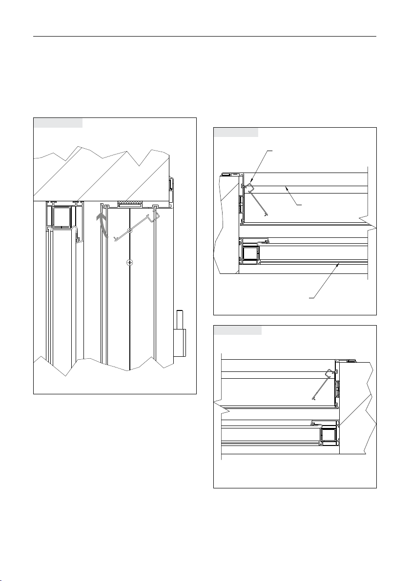
Fastening the clip profiles
Insert the top clip profile in the lintel into the
frame groove and clip into place
Clip profile, lintel
Insert the clip profiles on the left-hand and
right-hand sides in the reveal into the frame
groove and clip into place
Clip profile, left
Clip profile
Lintel
Window
Clip profile, left
Clip profile, right

15
2 Installation instructions
Fastening the clip profiles when installing VOLETRONIC (optional)
Mount the installation profile and fasten the
drive modules
Attach the cover
Installation
profile
Drive module
Cover
VOLETRONIC header installation
NOTES
Detailed instructions for the installation of the
EHRET VOLETRONIC io or VOLETRONIC Solar
shutters can be found in the enclosed installa-
tion and operating instructions:
E 641 VOLETRONIC io resp.
E 668 VOLETRONIC Solar.
VOLETRONIC
io
Motorisation for window shutters
Installation and
operating instructions
INSTALLATION
SPECIALIST PERSO NNEL
Valid from 03.2021
E 641.4
VOLETRONIC Solar
Motorisation for window shutters
Installation and
operating instructions
INSTAL LATI ON
SPECIALIST PERSONNEL
Valid from 01.2020
E 668.3
Insert the clip profiles on the left-hand and
right-hand sides in the reveal into the frame
groove and clip into place
Clip profile, left
Clip profile
Lintel
Window
Clip profile, left
Clip profile, right

© 02.2022 EHRET GmbH | E 639.2 | This technical document includes information that is protected by copyright. All rights are re-
served. We reserve the right to make changes, including technical changes, in this document.This document has been prepared with
great care. Liability will not be assumed for any errors that might still exist and their consequences.
EHRET GmbH
Aluminium shutters
Bahnhofstrasse 14 - 18
77972 Mahlberg, Germany
Tel. + 49 (0) 78 22/439 - 0
Fax + 49 (0) 78 22/439 - 116
www.ehret.com
Table of contents
Other EHRET Indoor Furnishing manuals


Popular Indoor Furnishing manuals by other brands

Asko
Asko VITA 2 U-FORM Assembly instructions

GFW
GFW LANCASTER WARDROBE Assembly instructions

Home affaire
Home affaire 791946 Assembly instructions

Extremis
Extremis dirk wynants PONTSUN Assembly instructions

Lightolier
Lightolier Lighting Systems LP-4 Specification sheet

Safavieh Furniture
Safavieh Furniture SEA8018 quick start guide


