EHRET Voletronic io User manual

VOLETRONIC io
Motorisation for window shutters
Installation and
operating instructions
INSTALLATION
SPECIALIST PERSONNEL
Valid from 03.2021
E 641.4

2
Notes
The present Installation and operating instruc-
tions describe the commissioning of the EHRET
VOLETRONIC io window shutter drive with
wireless remote control.
Carefully read through these operating instruc-
tions prior to commissioning. Observe the
specified process steps and take into account
the notes and recommendations given. Knowl-
edge of and technically impeccable implemen-
tation of the given safety notes and warnings
are prerequisite for the safe and proper opera-
tion of the VOLETRONIC io window shutter
drive. Insufficient knowledge at the time of
commissioning and utilisation leads to the loss
of any liability claims against EHRET GmbH.
Any installation or operation in deviation from
our installation and operating instructions – ei-
ther in full or in part – will result in the warranty
becoming void.
Installation of the shutters in accordance with
the EHRET window shutter installation instruc-
tions is a prerequisite for the commissioning of
the EHRET VOLETRONIC io window shutter
drive.
Remove the labels stuck to the shutters after
installation!
These Installation and operating instructions
are addressed to qualified specialist personnel.
Qualified specialist personnel are persons who
are familiar with the transport, setup, installa-
tion, commissioning and operation of the prod-
uct and who have appropriate qualifications for
their work. Specialist personnel must know and
observe the relevant standards and/or guide-
lines.
These Installation and operating instructions
are a component part of the product and are
therefore always to be retained until the prod-
uct is disposed of.
These Installation and operating instructions
are to be passed along in the event of the sale
of this product. This product is in accordance
with general rules of technology. Safety-con-
scious behaviour is necessary for undertaking
safe commissioning. For this reason, observe
the following notes.
Should you not understand something in these
Installation and operating instructions unam-
biguously, do not fail to contact the specialist
personnel at EHRET GmbH, 77972 Mahlberg
(Germany).

3
Contents
Notes . . . . . . . . . . . . . . . . . . . . . . . . . . . . . . . . . . . . . . . . . . . . . . . . 2
Explanation of signs and symbols . . . . . . . . . . . . . . . . . . . . . . . . . . . . . . . . . 4
Safety notes . . . . . . . . . . . . . . . . . . . . . . . . . . . . . . . . . . . . . . . . . . . . .4
EC Declaration of Conformity . . . . . . . . . . . . . . . . . . . . . . . . . . . . . . . . . . 6
Installation FAQs . . . . . . . . . . . . . . . . . . . . . . . . . . . . . . . . . . . . . . . . . . 7
Electrical installation . . . . . . . . . . . . . . . . . . . . . . . . . . . . . . . . . . . . . . . . .7
Disposal . . . . . . . . . . . . . . . . . . . . . . . . . . . . . . . . . . . . . . . . . . . . . . 8
1 Product description
Product properties . . . . . . . . . . . . . . . . . . . . . . . . . . . . . . . . . . . . . . 9
Scope of delivery . . . . . . . . . . . . . . . . . . . . . . . . . . . . . . . . . . . . . . . 10
2 Installation instructions
Preparation . . . . . . . . . . . . . . . . . . . . . . . . . . . . . . . . . . . . . . . . . . 12
Mounting the installation profile and fastening the drive modules . . . . . . . . . . . . . . 13
Cable routing and wiring . . . . . . . . . . . . . . . . . . . . . . . . . . . . . . . . . . . 17
Attaching the cover . . . . . . . . . . . . . . . . . . . . . . . . . . . . . . . . . . . . . . 18
Attaching sash arms with guide rails on the drive . . . . . . . . . . . . . . . . . . . . . . 18
Attaching guide rails to the sash . . . . . . . . . . . . . . . . . . . . . . . . . . . . . . . 19
Commissioning . . . . . . . . . . . . . . . . . . . . . . . . . . . . . . . . . . . . . . . . 20
Cutting the coupling rod to size and mounting it . . . . . . . . . . . . . . . . . . . . . . . 24
Crimped metal ribbon . . . . . . . . . . . . . . . . . . . . . . . . . . . . . . . . . . . . . 25
3 Operation
Opening and closing . . . . . . . . . . . . . . . . . . . . . . . . . . . . . . . . . . . . . 26
Preferred position “my” . . . . . . . . . . . . . . . . . . . . . . . . . . . . . . . . . . . . 26
Detecting obstacles and freeze protection . . . . . . . . . . . . . . . . . . . . . . . . . . 27
Activate the new setting mode . . . . . . . . . . . . . . . . . . . . . . . . . . . . . . . . 28
Reverse sash priority / direction of rotation . . . . . . . . . . . . . . . . . . . . . . . . . . 28
Setting the closing force . . . . . . . . . . . . . . . . . . . . . . . . . . . . . . . . . . . 29
Buzzer function . . . . . . . . . . . . . . . . . . . . . . . . . . . . . . . . . . . . . . . . 30
Reset to factory settings . . . . . . . . . . . . . . . . . . . . . . . . . . . . . . . . . . . 30
Radio transmitter “io Pure” . . . . . . . . . . . . . . . . . . . . . . . . . . . . . . . . . . 31
4 Maintenance
Installing the emergency battery . . . . . . . . . . . . . . . . . . . . . . . . . . . . . . . 32
Restore factory settings . . . . . . . . . . . . . . . . . . . . . . . . . . . . . . . . . . . 34
Restore the initial configuration . . . . . . . . . . . . . . . . . . . . . . . . . . . . . . . . 34
Operator interface of the drive . . . . . . . . . . . . . . . . . . . . . . . . . . . . . . . . 35
List of setting parameters . . . . . . . . . . . . . . . . . . . . . . . . . . . . . . . . . . 36
Troubleshooting . . . . . . . . . . . . . . . . . . . . . . . . . . . . . . . . . . . . . . . . 38
Error codes on the user interface of the drive . . . . . . . . . . . . . . . . . . . . . . . . 39

4
Important notes
Explanation of signs and symbols
Warning notes
DANGER
Designates an immediately pending dan-
ger that could lead to death or severe in-
juries if the respective precautionary
measures are not implemented.
WARNING
Means that death, severe bodily injury or
major property damage could occur if the
respective precautionary measures are
not implemented.
CAUTION
Means a possibly pending danger that
could lead to minor injuries or property
damage if it is not avoided.
Directives for action
Safety notes
Only qualified specialist personnel may
carry out installation and commission-
ing!
WARNING
Incorrect installation could lead to se-
vere injuries and/or damage to prop-
erty.
Follow all installation instructions.
WARNING
Take into account the following notes
and warnings in order to avoid dangers
and to protect the product.
Observe the accident prevention regula-
tions of the Accident Prevention & Insur-
ance Association.
Observe the rules of the road during trans-
port.
Make sure that the load is well-secured on
the means of transport.
Take care to ensure that the drives are
stored under dry conditions prior to final in-
stallation and commissioning.
Cordon off a generously large area around
the installation site.
Observe without limitation the regulations
of the manufacturers of dowel and attach-
ment materials.
The mounting bases of the installation site
are to be checked for load-bearing capacity
prior to installation.
In the event of uncertainties about the
mounting bases, contact your responsible
building experts.
Electrical work may be carried out only by
authorised electricians.

5
Important notes
The specified connection diagrams are to
be observed, as otherwise damage to the
motor could occur. EHRET GmbH assumes
no liability for damage resulting from incor-
rect installation.
Check the product for damage prior to in-
stallation. Products requiring repair may not
be used.
Do not touch any internal parts of the prod-
uct that become exposed as the result of
damage (e.g. electrical cables/lines).
Discontinue operation of your electrical
drive at once in the event of smoke or
fumes.
Do not allow children to play with the oper-
ating apparatus of the drives.
Electrical/electronic devices are not secure
against failure. Make sure that no hazard-
ous situations for personnel or product
could arise in the event of a power failure.
Devices with electrical controls could go
into motion at any time and without warn-
ing. Prevent situations hazardous to person-
nel and product that arise from this fact.
No personnel or obstacles are permitted to
be within the range of pivoting and/or trav-
elling shutters while they are moving. Keep
personnel and objects away until the shut-
ters have reached their final position.
Do not reach into moving parts or closing
areas while shutters are opening or closing.
Make sure that no articles of clothing or
body parts are able to be caught by moving
parts in the system.
Disconnect the drives from the power sup-
ply during maintenance work.
Ice could form on the product in the event
of snowfall, sleet or icy rain. Do not operate
equipment until the ice formation is no
longer present, and switch automatic con-
trols to manual.
Make sure that the shutters are locked be-
fore any wind load occurs.
The shutters may not be operated at wind
speeds from 62 km/h (stormy wind).
No additional loads such as persons or ob-
jects are permitted to have an effect on the
shutters.
Shutters are not intended to protect indi-
viduals from falls.
WARNING
Danger of injury from the weight of
the product!
Due to the weight of the products,
perform transport and installation by at
least two individuals.
Transport the product carefully in order to
avoid damage.
Take care to ensure that the product is not
damaged when the packaging material is
removed.
WARNING
Danger of suffocation from packaging
foil.
The packaging foil must be kept out of
reach of children.
Store the foil carefully until you turn it
in for recycling.
Turn the packaging materials in for recy-
cling.

6
Important notes
EC Declaration of Conformity
The manufacturer: EHRET GmbH
Aluminium Shutters
Bahnhofstrasse 14 - 18
D-77972 Mahlberg
declares that the product: EHRET window shutter drive
VOLETRONIC io
to which this guideline refers, is in conformance with the stipulations of
2006/42/EC Machinery Directive
2014/53/EC Radio Equipment / R&TTE
2011/65/EU + 2015/863 RoHS Directive
+ 2017/2102
as well as with the following standards:
EN 60335-1:2012 + A1:2019 + A11:2014 + A13:2017 + A14:2019 + A2:2019
EN 60335-2-97: 2006 + A11:2008 +A12:2015 + A2:2010
EN 62233: 2008 ; EN 62479:2010
EN 301489-1 V2.2.3:2019 ; EN 301489-3 V2.1.1: 2019; EN 55014-1:2017 ; EN 55014-2:2015;
EN 61000-3-3:2013 + A1:2019 ; EN IEC 61000-3-2:2019
EN 300220-1 V3.1.1: 2017 ; EN 300220-2 V3.1.1: 2017 ; EN 300220-2 V3.2.1: 2018
EN IEC 63000:2018
—
Name and address of the individual who is authorised to assemble the technical documentation:
Ralf Gielen Location: D-77972 Mahlberg
Head of Technology Date: 01/ 03/ 2015
EHRET GmbH
Eberhard Schopferer
Management

7
Important notes
Installation FAQs
Which parts have been delivered?
• VOLETRONIC io window shutter drive
• Depending on the diagram, 1× or 2× guide
rail and carriage arm
• 1× adhesive buffer, 1× stop buffer, 2× sup-
port for stop buffer per sash
• Coupling set with coupled window shutters
• Optional support for end piece of window
shutter drive, pair
Which means of attachment are being used?
• The means of attachment are not included in
the scope of delivery!
• The selection of the attachment materials
is oriented towards the mounting bases on
hand, the load-bearing capacities of which
are to be checked before the installation.
Observe without limitation the regulations
of the manufacturers of dowel and attach-
ment materials.
WARNING
Danger of injury/property damage caused
by unsuitable fastening materials
The means of attachment are to be select-
ed in accordance with the load-bearing ca-
pacity of the mounting bases.
How is the VOLETRONIC io window shutter
drive mounted?
• First, the installation prole is aligned and
mounted and the drive modules are hooked
into place and attached.
• Then the carriage arms, guide rails and the
stop buffer are mounted, during which the
drive is connected and put into operation
and the priority of the sashes is checked at
the same time that the carriage arms are in-
stalled.
• Afterwards, the coupling rod is cut to size
and mounted in the case of multiple-section
sashes, and, if express hinges are used, then
these are secured.
Electrical installation
WARNING
Electrical shock (230 V)
NOTES
• The connection (Phase L) must be equipped
with a line safety switch with a maximum
nominal current of 6 A.
• The line safety switch must have a switch-off
capacity of at least 6 kA.
• The prescribed tripping characteristic is B.
• The line switch should be equipped with a
thermal tripping device for overload protec-
tion, furthermore it should have an electro-
magnetic trigger as a protection against short
circuits.
• Other requirements may apply to the instal-
lation of the line safety switch, depending
on the location. For example, it could be
necessary to use a line safety switch with
additional separation of Phase N in order to
switch off all poles. It might possibly also be
necessary to have a residual current circuit
breaker in the system. The standards and the
laws of the respective country with respect
to permanent electrical installations are to be
complied with (e.g. VDE 0100).
• It is recommended that no more than ve
drives are secured simultaneously by a single
line safety switch.
• Pursuant to VDE 0100 and/or the statutory
regulations and standards of the respective
country, the permanent electrical installation
must be carried out by a certified electrician.
• According to VDE 0022, the operator and the
installer are responsible for compliance with
the VDE regulations and/or regulations of the
energy supplier.

8
Important notes
Disposal
IMPORTANT
Disposal
• The following information must be strictly
adhered to in order to prevent any environ-
mental damage. Even if the machine is dis-
posed of by certified experts, the operator
must ensure proper execution!
Some materials of the machine are reusable.
By recycling some parts or raw materials from
used products, you make an important contri-
bution to protecting the environment.
Please contact your local authorities if you
require information about collection points
near you.
Recyclable materials of the machine
Reusable
material
Components
Aluminium • Shutters
• Drive housing
• Coupling
• Guide rail
• Fittings
Copper • Cables
• Motor
Plastic,
rubber, PVC
• Guides
• Accessories
• Sealing sleeves
• Cables
Steel • Motor and components
• Coupling
• Carriage arm
• Fittings
• Accessories
IMPORTANT
Disposal
Dispose of all machine parts in accordance
with the applicable legal conditions in or-
der to prevent the possibility of any harm
to human health or the environment.
Hazardous waste
Reusable
material
Components
Electronic
waste
• Electrical supplies
• Control units
• Circuit boards with
electronic components

9
1 Product description
1 Product description
Product properties
Technical data
Power supply 230V – 50 Hz
Emergency 9.6 V/1600 mAh;
rechargeable battery in the event of a
(optional) power failure
Drive housing according to diagram:
(1L/1R, 2) 92 × 66 mm (w × h)
(2L/2R, 3L/3R, 4) 106 × 66 mm (w × h)
Connection cable 3 m, 2-wire, 0,75 mm2
cable exit on the right
or left window side
Nominal torque 4 Nm per motor,
peak torque 50 Nm
Speed 1,5 rpm.
Power consumption max. 50W
Disconnection Load switch-off
Protection class II
Degree of protection IP 24
Operating –20° C to +60° C
temperature
• VOLETRONIC io is a drive system for a max.
of 2 sashes per side for the electronic actuati-
on of window shutters.
• The drive is equipped with tri-band bidirec-
tional (io-homecontrol®) and is suitable for all
types of window shutters.
• Operation takes place via the supplied
wall transmitter Smoove 1 O/C RTS, radio
frequency 868-870 MHz or optionally via
1-channel or 5-channel hand-held transmit-
ter (Situo io Pure II) or Handheld transmitter
Nina io (bidirectional touch display control).
• The VOLETRONIC io folding shutter drives
are checked and delivered fully charged.
• The drives are pre-programmed for mounting
type, stop scheme, side of the cable exit, di-
rection of rotation and priority of the sashes,
closing force as well as time delay for spe-
cial construction situations (e.g. 90° opening,
overlapping of the sashes).
1× 2×
1× 2×
2× Ø 4,8 S3
10
1 Product description
VOLETRONIC io
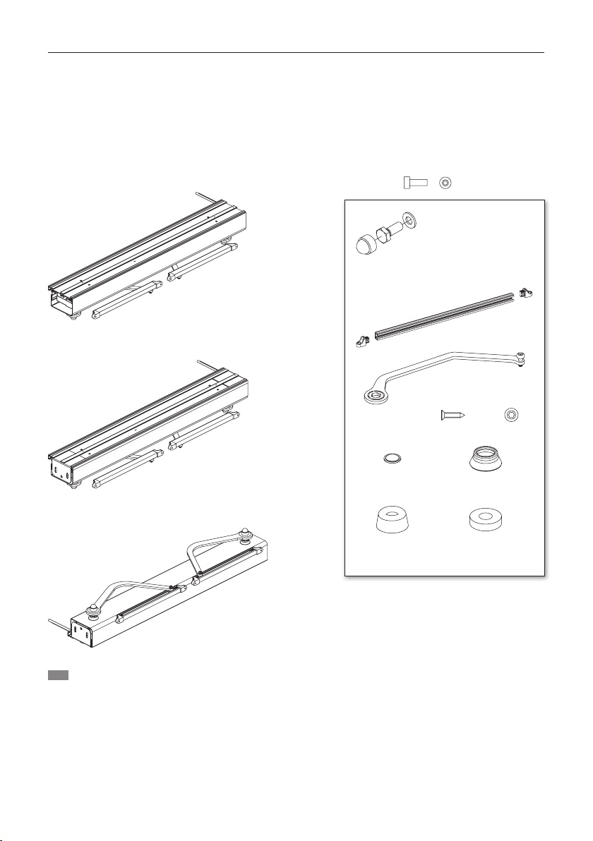
Scope of delivery
Motorisation for window shutters
Variante A
Header installation
Accessories per sash
M3 × 6 mm S1
1× (1L/1R, 2L/2R); 2× (2, 3L/3R, 4)
Adhesive buffer Shaft seal ring
Stop buffer Support for
stop buffer
Guide rail
Carriage arm
Variant B
Reveal installation
(on the side)
Variant C
At the bottom above
the windowsill
INFO Fastening material at the installation site
(for all variants)
Washer Ø10.5 mm A2
S2 Hexagon screw M10 × 20
Cover cap, hexagon, WAF17

1× (1L/1R, 2L/2R); 2× (2, 3L/3R, 4):
2× Ø 4,8 × 32 mm S4
11
1 Product description
Torx
TX 20+25
Gr. 10
Masonry drill
Drill Ø 4.2 mm
Coupling with multiple-section sashes
2L/2R, 3L/3R, 4
Operation
6440 wall transmit-
ter Smoove 1O/C io
Pure Shine, wireless
Situo io Pure II
hand-held transmit-
ter (optional)
6441 1-channel
6642 5-channel
6643 Nina io hand-
held transmitter (bidi-
rectional touch display
control)
6220 Support for end piece of window
shutter drive, pair
To be used with window shutter models with
protruding slats
6360 Cover remover
for simplified subsequent
dismantling of the cover
6406 Emergency battery, 9.6 V / 1600 mAh,
(optional)
6631 Extension cable
3m
Optionen
Guide lug
Guide rod
Pivot bearing
2× rivets N1
WAF4
WAF17
WAF2.5
Tools required*
*not included in the scope of delivery
12
2 Installation instructions
2 Installation instructions
Preparation
NOTES
Before mounting the drive, make sure that each sash of the folding shutter can be moved freely
over the entire swivel range. The folding shutter must not jam or rub against its immediate sur-
roundings (frame, masonry, etc.). The resistance of the folding shutter must not exceed a torque of
4 Nm during movement.
Remove any pre-existing locking elements (e.g. shutter bolt, espagnolette, etc.).
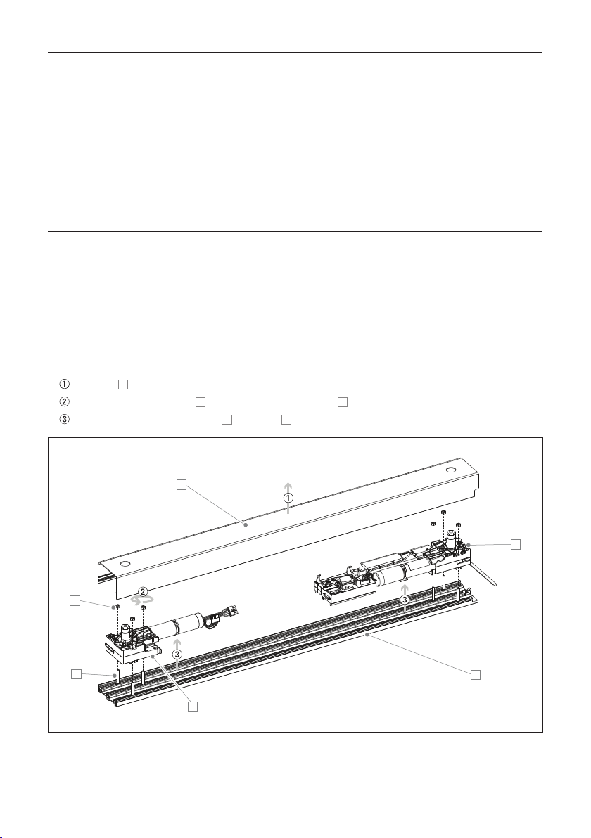
Dismantle cover and drive modules
Remove Athe cover
Loosen the 6 drive nuts B, leave the 6 drive screws Cin the installation profile
Remove the 2 drive modules Dfrom the Einstallation profile
A
B
CE
D
D

13
2 Installation instructions
Mounting the installation profile
and fastening the drive modules
WARNING
Danger of injury/property damage caused by
unsuitable fastening materials
Select the fastening material in accordance
with the load capacity of the installation sub-
strates!
NOTES
• The selection of the fastening method is de-
pendent on the substrate and is therefore
exclusively your own responsibility.
• Note that the lintel must be horizontal in both
width and depth.
• The dowels used must be able to withstand a
force of at least 40 kg. The brackets must be
fastened at at least two points.
• EHRET recommends the use of screws with
a diameter of at least 6mm.
14
2 Installation instructions
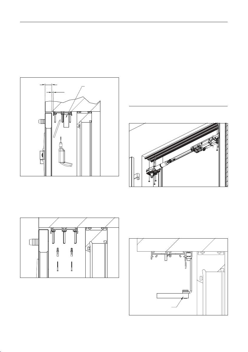
Variant A
Header installation
Position the installation profile with shutters
closed (dimension X + 5 mm) and align it
horizontally.
X
5Spirit level
X = sash thickness in the reveal
Mark and drill the fastening holes.
Fasten installation profile at at least four
points.
Insert the electromechanical module into the
frame on the side where the power supply
enters.
Insert the drive modules into the installation
profile, move them as far as they will go (limit
screw S1) and fasten them with the drive
nuts.
NOTE
Do not screw the drive nuts too tightly!
For multiple-section sashes
Diagram 2L/2R, 3L/3R, 4
Insert pivot bearings into the installation pro-
file when coupling multi-section sashes!
Pivot bearing

15
2 Installation instructions
Variant B
Reveal installation
Position the installation profile with lateral
fastening brackets (dimension X + 5 mm) and
align it vertically and horizontally with a spirit
level; drill and attach.
X
5
Spirit level
Fastening bracket
X = sash thickness in the reveal
CAUTION
Property damage caused by sliding of the
drive due to insufficient fastening
Use security bore hole!
2.3_B
Security
bore hole
Insert the electromechanical module into the
frame on the side where the power supply
enters.
Insert the drive modules into the installation
profile, move them as far as they will go (limit
screw S1) and fasten them with the drive
screws.
NOTE
Do not screw the drive nuts too tightly!
For multiple-section sashes
Diagram 2L/2R, 3L/3R, 4
Insert pivot bearings into the installation pro-
file when coupling multi-section sashes!
Pivot bearing
16
2 Installation instructions
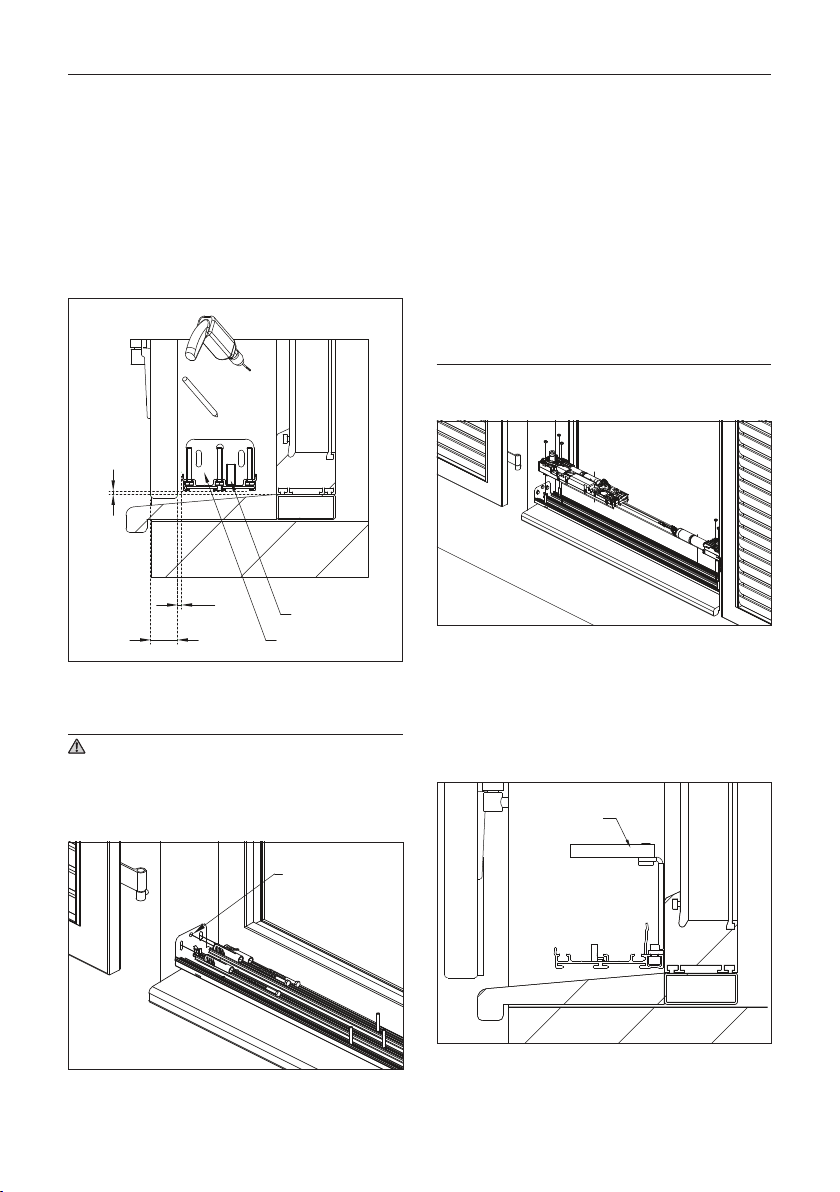
Variant C
At the bottom above the windowsill
Position the installation profile with lateral
fastening brackets at the bottom above the
windowsill (dimension X + 5 mm) and align
it vertically and horizontally with a spirit level;
drill and attach.
X
5
Y = min. 5 mm
Spirit level
Fastening bracket
X = sash thickness in the reveal
Y = air (upper edge of windowsill to lower edge of installation
profile), min. 5 mm
CAUTION
Property damage caused by sliding of the
drive due to insufficient fastening
Use security bore hole!
Security
bore hole
Insert the electromechanical module into the
frame on the side where the power supply
enters.
Insert the drive modules into the installation
profile, move them as far as they will go (limit
screw S1) and fasten them with the drive
screws.
NOTE
Do not screw the drive nuts too tightly!
For multiple-section sashes
Diagram 2L/2R, 3L/3R, 4
Insert pivot bearings into the installation pro-
file when coupling multi-section sashes!
Pivot bearing

17
2 Installation instructions
Cable routing
WARNING
Electrical shock (230 V) resulting from dam-
age to cable
Pass the cable through the cable holder to
guarantee electrical safety and the integrity
of the cable.
CAUTION
Danger of crushing/property damage from
incorrect cable placement
Install the electromechanical module next to
the voltage supply inlet. Note while doing so
that the mains cable proceeds outward from
the product on the window side!
Do not disconnect the mains cable in the
area between the drive and the red cable
marking!
Cable holder
Wiring
WARNING
Electrical shock (230 V) resulting from dam-
age to cable
Protect mains cable against contact with the
activated window shutter!
CAUTION
Impairment of the antenna and the radio
range
Do not alter the placement of the cables in
the interior of the product!
Do not cut off the cable in the interior of the
product!
Always switch off the power supply via the
mains cable before each operation.
OFF
Connect the drive as follows:
230 V 50 Hz
VOLETRONIC io
Switch on the voltage supply.
ON
The VOLETRONIC io folding shutter drive con-
firms by means of an audible signal. If this is not
the case, check the electrical connection again.
Switch off the power supply again after
checking the electrical connection.
OFF
18
2 Installation instructions
Attaching the cover
WARNING
Electrical shock (230 V) resulting from dam-
age to cable
Position the recess of the cover on the side
with the mains cable!
Protect the mains cable against crushing by
the cover of the drive housing!
Hold the cover parallel and clip it firmly in
place.
Attach adhesive buffers.
Sealing
sleeve
Place the left and right sealing sleeves on
the drive axle and press them onto the trim
cover.
Drive axle
Sealing sleeve
Sample drawing – variant C
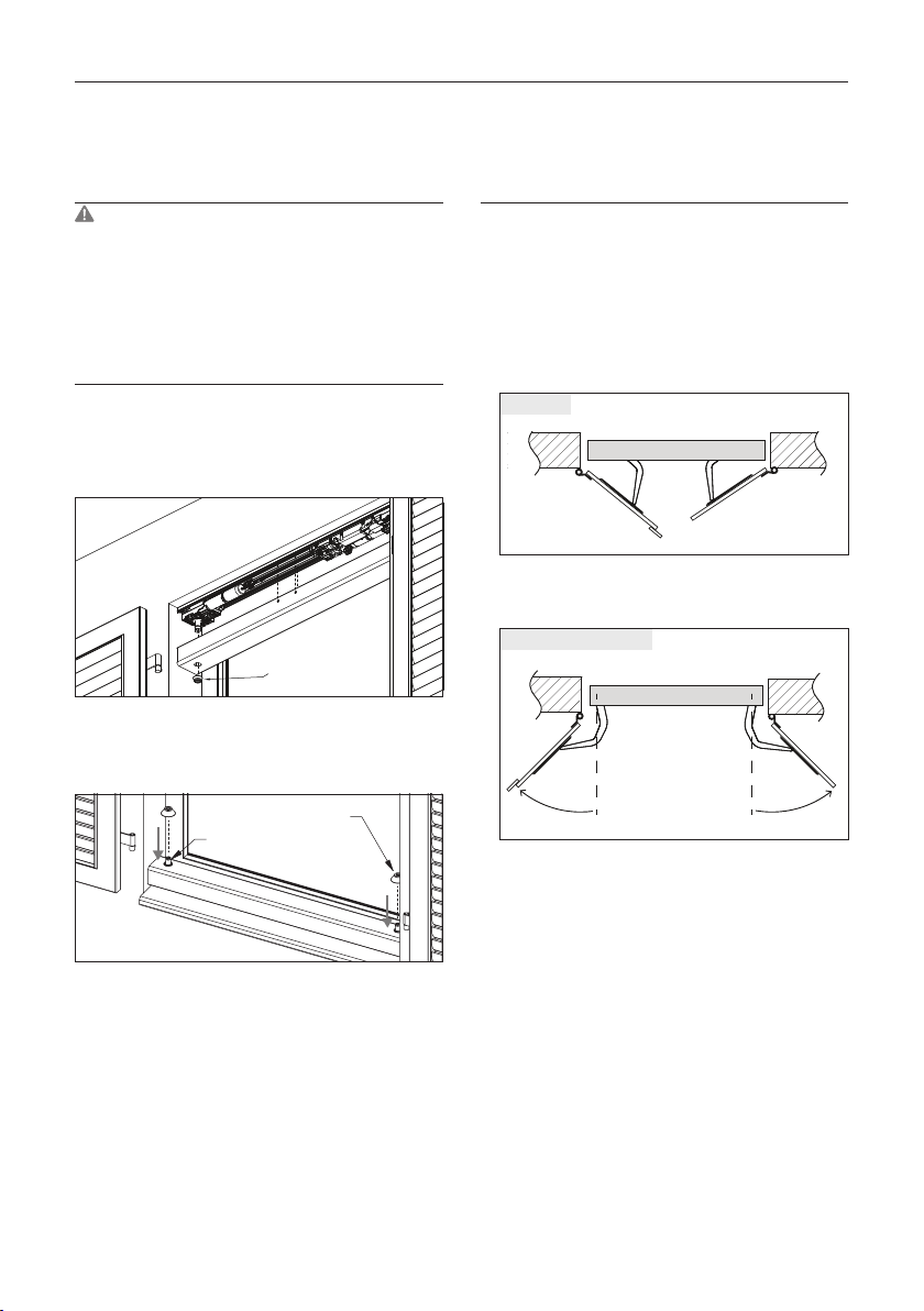
Attaching sash arms with guide
rails on the drive
NOTES
• The swivel arms must be fitted in accord-
ance with one of these two recommenda-
tions:
a) half open, outside the end positions, ob-
serving the sequence of the covered sash
and the sash with cover strip
Half open
VOLETRONIC io
b) at an angle of more than 90°outside the
open end position.
VOLETRONIC io
90° 90°
Angle of more than 90°
• Note whether a left-hand or right-hand sash
arm is required.
• The castor of the sash arm must be posi-
tioned at the middle of the guide rail at the
time of installation.
• The joints of the guide rails must face down-
wards at the time of installation.
• Remove all objects that could obstruct the
movement of the folding shutter.
• Do not use a hammer during assembly.

19
2 Installation instructions
Thread the sash arm into the guide rail and
plug the end pieces into the guide rail
Sash arm
End piece
Guide rail
Set the sash arm on the drive hex nut and
fasten with the self-locking S2 screws pro-
vided
Use the washers provided.
Set covers on S2 screw.
Guide rail
with end pieces
Drive hex nut
Sash arm with
castor
S2
Cover cap WAF17
Washer
Attaching guide rails to the sash
NOTES
Observe the edge clearance of the guide rails
with rabbet or surface-mounted installation.
For models with protruding slats, use the 6220
supports for end pieces of window shutter drive
with the corresponding S4 screws.
When selecting screws for window shutters
made of wood (a decision that is the exclusive
responsibility of the installer), care must be
taken to ensure that the sliding guides cannot
be torn off.
Centre the guide rail in the sash width and
use a spirit level to align it horizontally.
Mark fastening holes, drill them with a
Ø 4.2 mm drill bit and fasten them with the
S3 screws supplied.
94.5
86
ca. 3 mm
111
S3
Adhesive buffer
Stop buffer
with support
Anschlagpuffer als Flügelanschlag montieren.
INFO
The stop buffers can be installed as stops either
on the exterior side of the sash at the top-outer
corner or on the façade.
20
2 Installation instructions
COMMISSIONING
NOTE
In order to carry out commissioning success-
fully, the following commissioning work steps
must be carried out consecutively and coher-
ently.
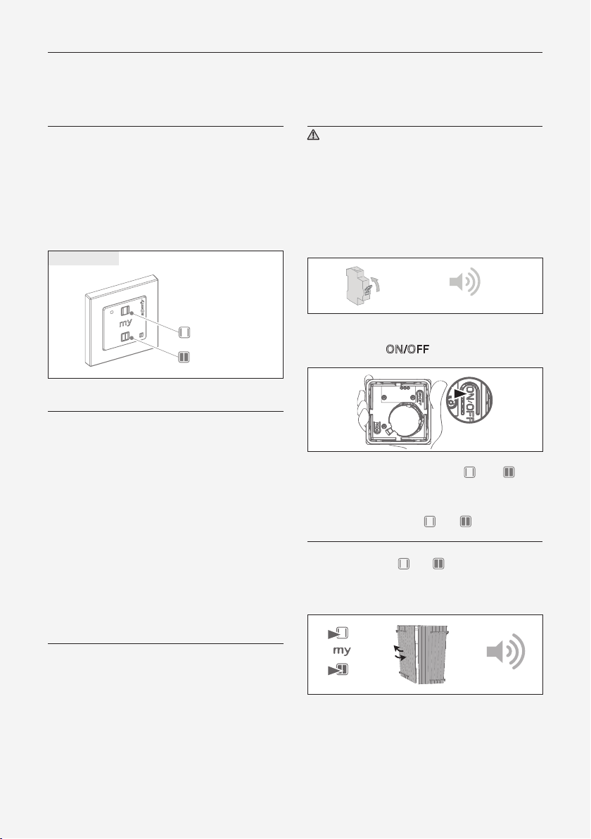
Wireless Radio wall transmitter
Smoove 1 O/C io
open
close
ACTIVATE RADIO WALL TRANSMITTER
(P. 20)
CHECK DIRECTION OF ROTATION AND
PRIORITY OF THE SASHES (P. 21)
SELF-LEARNING PROCESS (P. 21)
CONNECTING THE RADIO WALL
TRANSMITTER TO THE DRIVE (P. 23)
VERIFICATION OF PROPER FUNCTION-
ING (P. 23)
ACTIVATE RADIO WALL TRANSMITTER
CAUTION
Do not press against the sensitive side of the
wireless wall transmitter with the flat of the
hand because otherwise unintended com-
mands could be triggered.
Switch on the voltage supply.
The drive emits a beep.
beep
ON
Check that the radio wall transmitter is
switched on (ON/OFF).
Press and hold the buttons and only
until the product confirms the activation with
a short up/down movement and a signal tone.
Release the buttons and immediately!
ATTENTION!
If the and buttons and continue to be held
down after the drive has confirmed activation,
the drive blocks.
beep
Table of contents
Other EHRET Indoor Furnishing manuals


Popular Indoor Furnishing manuals by other brands

Courtyard Creations
Courtyard Creations XTM015W Assembly instructions

SEI
SEI BE6621 instruction manual

Salamander Designs
Salamander Designs SYNERGY SYSTEM SLC20 Assembly instructions

Emmezeta
Emmezeta AVA DD8018-4R Assembly instructions

Allen + Roth
Allen + Roth LWSK30VG manual

HULALA HOME
HULALA HOME SCBSD0590 manual


pottery barn kids
pottery barn kids EVERETT MODULAR DESK CUBBY BASE manual

Home affaire
Home affaire 23345327 Assembly instructions

Zedbed
Zedbed CUSTOM Z manual

Safavieh Furniture
Safavieh Furniture DSK9000 quick start guide

Coulisse
Coulisse Module 7 Installation instructions manual

Martin Svensson
Martin Svensson Space Saver 899922 Assembly instructions