EHRET PERSIENNE User manual
PERSIENNE
Aluminium folding shutters
Installation instructions
INSTALLATION BY
SPECIALIST PERSONNEL
Valid from 06.2017
E 634.1

2
Notes
These installation instructions describe the in-
stallation and commissioning of PERSIENNE
folding shutters.
Carefully read through these instructions prior
to commissioning. Observe the specified pro-
cess steps and take into account the notes and
recommendations given. Knowledge of and
technically impeccable implementation of the
given safety notes and warnings are prerequi-
sites for safe and proper operation of the fold-
ing shutters. Insufficient knowledge at the time
of commissioning and utilisation lead to the
loss of any liability claims against EHRET
GmbH. Installation and/or operation in full or
partial deviation from our installation and oper-
ating instructions will lead to the warranty for
defects becoming void.
These installation instructions are a component
part of the product and are therefore always to
be retained until the product is disposed of.
These installation instructions are to be passed
along in the event of the sale of this product.
These instructions are addressed to qualified
specialist personnel. Qualified specialist per-
sonnel are persons who are familiar with the
transport, set-up, installation, commissioning
and operation of the product and who have ap-
propriate qualifications for their work. Specialist
personnel must know and observe the relevant
standards and/or guidelines.
This product complies with the general rules of
technology. Safety-conscious behaviour is nec-
essary for commissioning the product safely.
For this reason, observe the following notes.
Should any of the information in these installa-
tion instructions not be absolutely clear, it is es-
sential that you contact the specialist personnel
at EHRET GmbH, 77972 Mahlberg (Germany).
Bore hole sizes and fastening material are rec-
ommendations only and may vary depending
on the substrate!

3
Contents
Notes. . . . . . . . . . . . . . . . . . . . . . . . . . . . . . . . . . . . . . . . . . . . . . . . .2
Explanation of signs and symbols . . . . . . . . . . . . . . . . . . . . . . . . . . . . . . . . . .4
Safety notes . . . . . . . . . . . . . . . . . . . . . . . . . . . . . . . . . . . . . . . . . . . . . 4
EC Declaration of Conformity . . . . . . . . . . . . . . . . . . . . . . . . . . . . . . . . . . 6
Installation FAQs . . . . . . . . . . . . . . . . . . . . . . . . . . . . . . . . . . . . . . . . . . .7
1 Product description
Scope of delivery . . . . . . . . . . . . . . . . . . . . . . . . . . . . . . . . . . . . . . . . 8
Tools required . . . . . . . . . . . . . . . . . . . . . . . . . . . . . . . . . . . . . . . . . . 9
Operating principle . . . . . . . . . . . . . . . . . . . . . . . . . . . . . . . . . . . . . . 10
2 Installation instrucions
Pre-drilling the hinge profile . . . . . . . . . . . . . . . . . . . . . . . . . . . . . . . . . . 12
Fastening sash packet 1 to the connection profile . . . . . . . . . . . . . . . . . . . . . . 12
Fastening sash packet 2 to the connection profile (for double-sided diagrams) . . . . . . . 13
Mounting the shutter catch . . . . . . . . . . . . . . . . . . . . . . . . . . . . . . . . . . 14
Mounting the stop angle. . . . . . . . . . . . . . . . . . . . . . . . . . . . . . . . . . . . 14
4
Important notes
Explanation of signs and symbols
Warning notes
DANGER
Designates an imminent danger that
could lead to death or severe injuries if
the respective precautionary measures
are not implemented.
WARNING
Means that death, severe bodily injury or
major property damage could occur if the
respective precautionary measures are
not implemented.
CAUTION
Means a possible danger that could lead
to minor injuries or property damage if it
is not avoided.
Directives for action
Safety notes
Only qualified specialist personnel may
carry out installation and commissioning!
WARNING
Incorrect installation could lead to se-
vere injuries and/or damage to prop-
erty.
Follow all installation instructions.
WARNING
Take into account the following notes
and warnings in order to avoid dangers
and to protect the product.
Observe the accident prevention regulations
of the Accident Prevention & Insurance As-
sociation.
Observe the rules of the road during trans-
port.
Make sure that the load is well-secured on
the means of transport.
Cordon off a generously large area around
the installation site.
Observe without limitation the regulations
of the manufacturers of dowel and fitting
materials.
The mounting bases of the installation site
are to be checked for load-bearing capacity
prior to installation.
In the event of uncertainties about the
mounting bases, contact your responsible
building experts.
Check the product for damage prior to instal-
lation. Products requiring repair may not be
used.

5
Important notes
No personnel or obstacles are permitted to
be within the range of pivoting and/or travel-
ling shutters while they are moving. Keep
personnel and objects away until the shut-
ters have reached their final position.
Do not reach into moving parts or closing
areas while shutters are opening or closing.
Make sure that no articles of clothing or
body parts are able to be caught by moving
parts in the system.
Ice could form on the product in the event of
snowfall, sleet or icy rain. Do not operate
equipment until the ice formation is no long-
er present, and switch automatic controls to
manual.
Make sure that the shutters are locked be-
fore any wind load occurs.
The shutters may not be operated at wind
speeds from 62 km/h (stormy wind).
No additional loads such as persons or ob-
jects are permitted to have an effect on the
shutters.
Shutters are not intended to protect individ-
uals from falls.
WARNING
Danger of injury from the weight of
the product!
Due to the weight of the products,
transport and installation must be car-
ried out by at least two individuals.
Transport the product carefully in order to
avoid damage.
Take care to ensure that the product is not
damaged when the packaging material is re-
moved.
WARNING
Danger of suffocation from packaging
foil.
The packaging foil must be kept out of
reach of children.
Store the foil carefully until you turn it in
for recycling.
Turn the packaging materials in for recy-
cling.
6
Important notes
EC Declaration of Conformity
(Original EC Declaration of Conformity)
In accordance with the Construction Products Directive 89/106/EEC
The manufacturer: EHRET GmbH
Aluminium shutters
Bahnhofstrasse 14 - 18
77972 Mahlberg, Germany
declares that the product: PERSIENNE folding shutter
Description of function: Sun/glare protection and screen
to which this guideline refers, meets the requirements of the EC Directives specified
above.
The following harmonised standards have been applied in full:
EN 13659: 2015-05 Shutters and external venetian blinds – Performance require-
ments including safety
EN 1932: 2013-06 External blinds and shutters – Resistance to wind loads
EN 13527: 1999-10 Shutters and blinds – Measurement of operating force
—
Name and address of the individual who is authorised to assemble the technical documentation:
Ralf Gielen Location: 77972 Mahlberg, Germany
Head of Technology Date: 01. 05. 2017
EHRET GmbH
Andreas Schnaase
Head of Sales
EHRET GmbH
Eberhard Schopferer
Management

7
Important notes
Installation FAQs
Which parts have been delivered?
• Sash packet per stop diagram, complete,
with pre-installed hinge profile and espagno-
lette closure
• Shutter catch and stop angle per stop dia-
gram, supplied loose in package, with acces-
sories (supporting block and rivets)
Which means of attachment are being used?
• The tting materials are not included in the
scope of delivery!
• The selection of the tting materials is based
on the mounting bases on hand, the load-
bearing capacities of which are to be checked
before the installation. Observe without limi-
tation the regulations of the manufacturers of
dowel and fitting materials.
WARNING
Danger of injury/property damage
caused by unsuitable fitting materials
The fitting materials are to be selected
in accordance with the load-bearing ca-
pacity of the mounting bases.
Which parts are to be positioned where on
the structure?
• Sash packet with pre-installed hinge profile
on the on-site connection profile
• Shutter catch on the reveal
• Stop angle in the centre of the espagnolette
• Additional central stop angles for joint profiles
PE-G60/-G80/-G100
What must be observed during on-site per-
formance?
• The connection profile must be aligned per-
pendicularly on-site prior to installation.
• The customer is responsible for ensuring that
the sash packets are properly fastened to the
connection profile and that suitable fitting ma-
terials are used.
WARNING
Danger of injury/property damage
caused by falling folding sliding sashes
Missing or incorrectly set locking parts
may result in the sash packets falling.
Secure the sash packets using the
shutter catches when open and the es-
pagnolette when closed.
CAUTION
Risk of cutting injuries caused by the
sharp edges on the vertical profiles
Use gloves for the installation.
What is to be taken into account with the
function check?
• In the case of double-sided diagrams, do
the sash packets align in the middle when
closed?
• Is there a sufficient gap (10 mm) between the
frame edge and edge of the reveal to prevent
the screw heads from touching?
• Are the locking parts, espagnolette and shut-
ter catches installed in the correct manner?

C
B
A
8
1 Product description
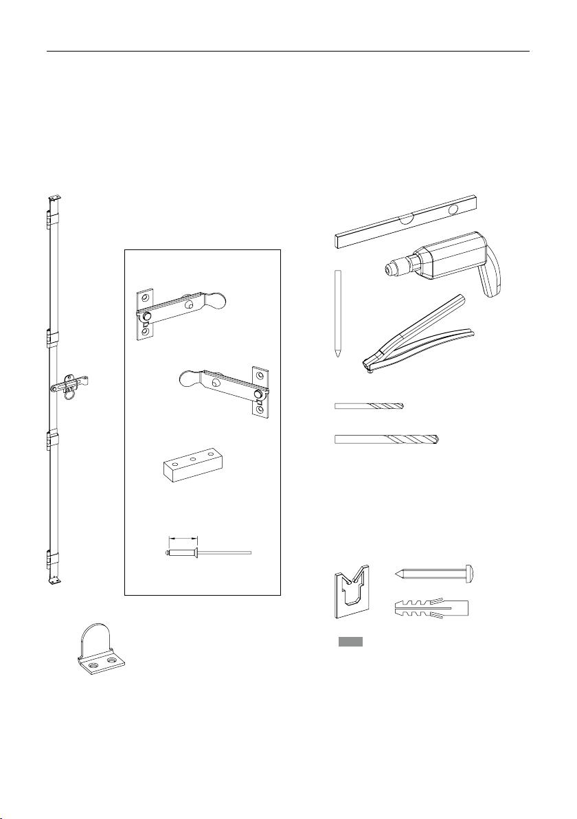
Scope of delivery
Contained in the scope of
delivery
PERSIENNE
Example view of 3L–3R
Sash packets
AEspagnolette closure, pre-installed
BShutter catch, loose
CStop angle, loose
Ex. 5L Ex. 5R
25
9
1 Product description
not included in the scope of delivery
Accessories
Drill Ø 5.1 mm
Drill for wall mounting
Tools required
not included in the scope of delivery
INFO Fitting material to be provided by the cus-
tomer!
Locking
Espagnolette closure
pre-installed
1× shutter catch
left
or
1× shutter catch
right
1× supporting block
2× N1 rivets (5×25)
2× stop angles for espagnolette closure
+ 2× stop angles each for joint profiles PE-G60/-G80/-G100
per sash packet

1
2
10
1 Product description
Right way to open (winding)
1
2
Closed PERSIENNE
Wrong way to open
Operating principle
Opening the PERSIENNE
Example 5L
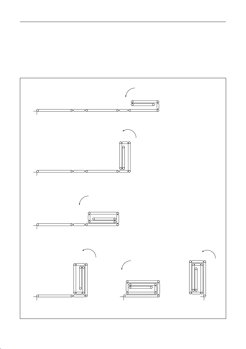
3
4
5
6 7 8
11
1 Product description
3
4
5
6 7 8
12
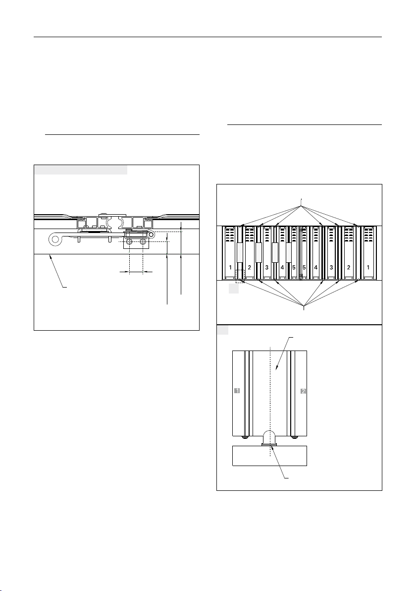
2 Installation instructions
2 Installation instructions
Pre-drilling the hinge profile
WARNING
Danger of injury/property damage caused by
unsuitable fastening materials
Select fastening material in accordance with
the load capacity of the installation substrates!
NOTE
The selection of the fastening method is de-
pendent on the substrate and is therefore ex-
clusively your own responsibility.
The connection profile must be aligned per-
pendicularly on-site
Unpack the delivery, check the state of the
items and that all items are included
Select the number of fastening holes as well
as connecting elements
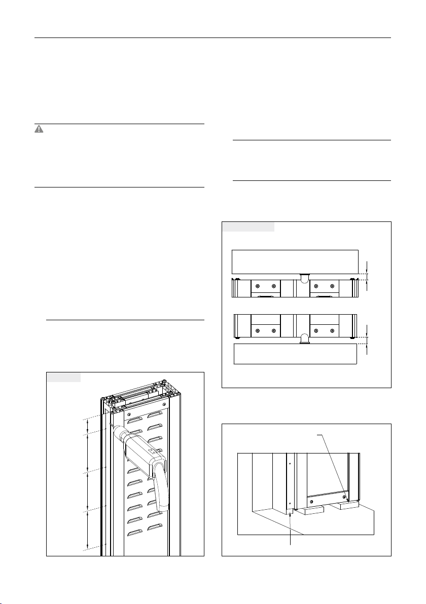
Pre-drill the hinge profile
EHRET recommends fastenings with a dis-
tance of max. 70 mm to the top/bottom
frame edges and max. 150mm between the
other fastenings.
max.
70
max.
150
max.
150
max.
150
Pre-drilling
Fastening sash packet 1 to the con-
nection profile
Place the support under the sash packet
Ensure that the screw heads do not touch
the upper edge of the reveal!
Check the gap at the top and bottom
There must be a 10mm gap between both
the upper or the lower sash edge and the
edge of the reveal
10
10
Checking the gap
Insert the sash packet with the pre-drilled
hinge into the connection profile
Support
Connection profile
13
2 Installation instructions
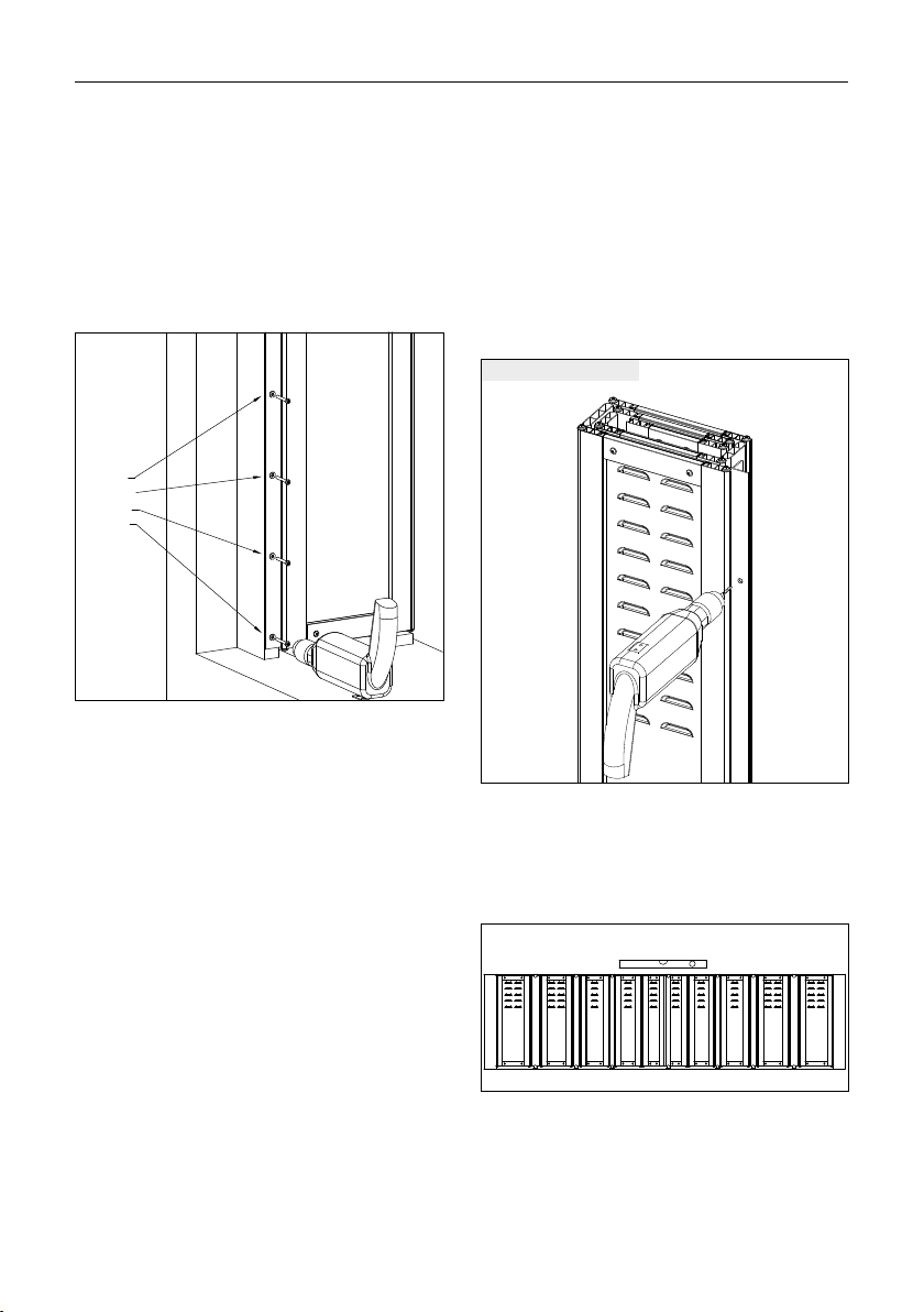
Fasten the sash packet with a suitable fitting
material in the connection profile
Fastening points
Fastening sash packet 2 to the con-
nection profile
(for double-sided diagrams)
First pre-drill and fasten the hinge profile at
two locations at the top/bottom
Pre-drilling sash packet 2
Place the support under sash packet 2
Check the gap at the top/bottom
Close both sash packets and check that they
align perpendicularly in the middle
Drill further fastening holes and fasten sash
packet 2 in the connection profile with a suit-
able fitting materiel
14
2 Installation instructions
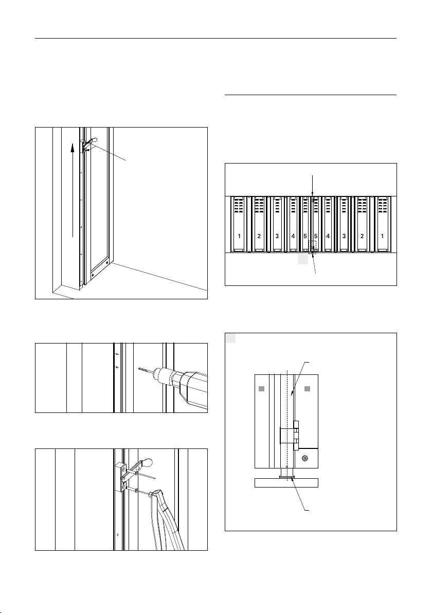
Mounting the shutter catch
Determine the operating height
Mark the holes
Holes
Operating height
Drill the marked holes with a Ø 5.1 mm drill
through the hinge profile and approx. 5mm
into the connection profile.
Rivet the supporting block and shutter catch
with N1 RIVETS.
Mounting the stop angle
NOTE
The selection of the fastening method is de-
pendent on the substrate and is therefore ex-
clusively your own responsibility.
Close the sash packet
A
Espagnolette stop angle
Espagnolette stop angle
Position the stop angle for the espagnolette
in the middle behind the closed espagno-
lette closure (see Fig. A).
A
55
Espagnolette closure
Stop angle
15
2 Installation instructions
Maintain a minimum distance from the win-
dow frame to the back of the stop angle (at
least 26 mm) or to the stop angle hole (at
least 15mm).
The minimum distance ensures you can
open and close the espagnolette properly.
16.5
min. 15
min. 26
Window frame
Minimum distance for stop angle
Drill the fastening holes
Fix the stop angles
Position additional stop angles for joint pro-
files PE-G60/-G80/-G100 in the middle of the
joint profiles (see Fig. B).
Ensure that the stop angles for joint profiles
are aligned with the previously mounted
stop angles for the espagnolette. No addi-
tional stop angle is provided for joint profile
PE-G20.
B
PE-G100
PE-G80
PE-G60
PE-G20
Joint profile stop angle
Joint profile stop angle
B
Joint profile
Stop angle
Drill the fastening holes
Fix the stop angles

© 01.2018 EHRET GmbH | E 634.1 | This technical document includes information that is protected by copyright. All rights are reserved.
We reserve the right to make changes, including technical changes, in this document. This document has been prepared with great
care. Liability will not be assumed for any errors that might still exist and their consequences.
EHRET GmbH
Aluminium shutters
Bahnhofstrasse 14 - 18
77972 Mahlberg, Germany
Tel. + 49 (0) 78 22/439 - 0
Fax + 49 (0) 78 22/439 - 116
www.ehret.com
Table of contents
Other EHRET Indoor Furnishing manuals


Popular Indoor Furnishing manuals by other brands


Home Decorators Collection
Home Decorators Collection WINDLOWE 15101-VS61C-WT Assembly instructions

idi
idi Aspect100RTL Operator's manual

Safco
Safco Plan Master Assembly instructions

sconto
sconto 992375 manual

New Classic Furniture
New Classic Furniture CELESTE T400-3P Assembly instruction

Ameriwood HOME
Ameriwood HOME 1816296COM Instruction booklet


