EHRET FSL-light User manual

Aluminium folding sliding shutters
FSL-light
Installation instructions
INSTALLATION BY
SPECIALIST PERSONNEL
Valid from 03.2016
E 619.2

2
Notes
These installation instructions describe the in-
stallation and commissioning of FSL-light fold-
ing sliding shutters.
These installation instructions are a compo-
nent part of the product and are therefore al-
ways to be retained until the product is dis-
posed of.
These installation instructions are to be passed
along in the event of the sale of this product.
These instructions are addressed to qualified
specialist personnel. Qualified specialist per-
sonnel are persons who are familiar with the
transport, set-up, installation, commissioning
and operation of the product and who have ap-
propriate qualifications for their work.
Specialist personnel must know and observe
the relevant standards and/or guidelines.
This product complies with the general rules of
technology. Safety-conscious behaviour is nec-
essary for commissioning the product safely.
For this reason, observe the following notes.
Carefully read through these instructions prior
to commissioning. Observe the specified pro-
cess steps and take into account the notes and
recommendations given. Knowledge of and
technically impeccable implementation of the
given safety notes and warnings are prerequi-
sites for safe and proper operation of the fold-
ing sliding shutters. Insufficient knowledge at
the time of commissioning and utilisation lead
to the loss of any liability claims against EHRET
GmbH.
Should any of the information in these installa-
tion instructions not be absolutely clear, it is es-
sential that you contact the specialist personnel
at EHRET GmbH, 77972 Mahlberg (Germany).
Bore hole sizes and fastening material are rec-
ommendations only and may vary depending
on the substrate!

3
Contents
Notes . . . . . . . . . . . . . . . . . . . . . . . . . . . . . . . . . . . . . . . . . . . . . . . . 2
Explanation of signs and symbols . . . . . . . . . . . . . . . . . . . . . . . . . . . . . . . . 4
Safety notes. . . . . . . . . . . . . . . . . . . . . . . . . . . . . . . . . . . . . . . . . . . . .4
EC Declaration of Conformity . . . . . . . . . . . . . . . . . . . . . . . . . . . . . . . . . 6
Installation FAQs . . . . . . . . . . . . . . . . . . . . . . . . . . . . . . . . . . . . . . . . . . 7
1 Product description
Scope of delivery . . . . . . . . . . . . . . . . . . . . . . . . . . . . . . . . . . . . . . . . 8
2 Installation instructions
Preparation. . . . . . . . . . . . . . . . . . . . . . . . . . . . . . . . . . . . . . . . . . . 10
Pre-drilling the guide rail. . . . . . . . . . . . . . . . . . . . . . . . . . . . . . . . . . . . 10
Mounting the guide rail . . . . . . . . . . . . . . . . . . . . . . . . . . . . . . . . . . . . 11
Installing the hinges on the sashes . . . . . . . . . . . . . . . . . . . . . . . . . . . . . . 12
Installing the accessories on the hinge sash . . . . . . . . . . . . . . . . . . . . . . . . . 13
Installing the accessories on the access sash . . . . . . . . . . . . . . . . . . . . . . . . 14
Installing the hinge sash . . . . . . . . . . . . . . . . . . . . . . . . . . . . . . . . . . . . 16
Setting the locking plate . . . . . . . . . . . . . . . . . . . . . . . . . . . . . . . . . . . . 18
Installing the guide. . . . . . . . . . . . . . . . . . . . . . . . . . . . . . . . . . . . . . . 19

4
Important notes
Explanation of signs and symbols
Warning notes
DANGER
Designates an imminent danger that
could lead to death or severe injuries if
the respective precautionary measures
are not implemented.
WARNING
Means that death, severe bodily injury or
major property damage could occur if the
respective precautionary measures are
not implemented.
CAUTION
Means a possible danger that could lead
to minor injuries or property damage if it
is not avoided.
Directives for action
Safety notes
Only qualified specialist personnel may
carry out installation and commission-
ing!
WARNING
Incorrect installation could lead to se-
vere injuries and/or damage to property.
Follow all installation instructions.
WARNING
Take into account the following notes
and warnings in order to avoid dangers
and to protect the product.
Observe the accident prevention regulations
of the Accident Prevention & Insurance As-
sociation.
Observe the rules of the road during trans-
port.
Make sure that the load is well-secured on
the means of transport.
Cordon off a generously large area around
the installation site.
Observe without limitation the regulations
of the manufacturers of dowel and fitting
materials.
The mounting bases of the installation site
are to be checked for load-bearing capacity
prior to installation.
In the event of uncertainties about the
mounting bases, contact your responsible
building experts.
Check the product for damage prior to instal-
lation. Products requiring repair may not be
used.

5
Important notes
No personnel or obstacles are permitted to
be within the range of pivoting and/or travel-
ling shutters while they are moving. Keep
personnel and objects away until the shut-
ters have reached their final position.
Do not reach into moving parts or closing
areas while shutters are opening or closing.
Make sure that no articles of clothing or
body parts are able to be caught by moving
parts in the system.
Ice could form on the product in the event of
snowfall, sleet or icy rain. Do not operate
equipment until the ice is no longer present.
Make sure that the shutters are locked be-
fore any wind load occurs.
The shutters may not be operated at wind
speeds from 62 km/h (stormy wind).
No additional loads such as persons or ob-
jects are permitted to have an effect on the
shutters.
Shutters are not intended to protect individ-
uals from falls.
WARNING
Danger of injury from the weight of
the product!
Due to the weight of the products,
transport and installation must be car-
ried out by at least two individuals.
Transport the product carefully in order to
avoid damage.
Take care to ensure that the product is not
damaged when the packaging material is re-
moved.
WARNING
Danger of suffocation from packaging
foil.
The packaging foil must be kept out of
reach of children.
Store the foil carefully until you turn it in
for recycling.
Turn the packaging materials in for recycling.

6
Important notes
EC Declaration of Conformity
(Original EC Declaration of Conformity)
In accordance with the Construction Products Directive 89/106/EEC
The manufacturer: EHRET GmbH
Aluminium shutters
Bahnhofstrasse 14–18
77972 Mahlberg, Germany
declares that the product: FSL-light folding sliding shutters
Description of function: Sun/glare protection and screen
to which this guideline refers, meets the requirements of the EC Directives specified above
The following harmonised standards have been applied in full:
EN 13659: 2015-05 Shutters and external venetian blinds –
Performance requirements including safety
—
Name and address of the individual who is authorised to assemble the technical documentation:
Ralf Gielen Location: 77972 Mahlberg, Germany
Head of Technology Date: 01. 03. 2015
EHRET GmbH
Andreas Schnaase
Head of Sales
EHRET GmbH
Eberhard Schopferer
Management

7
Important notes
Installation FAQs
Which parts have been delivered?
• Guide rail, cut to measure
• Guides left and right
• Sash packets, each containing two folding
sliding sashes
• Hinges pre-installed on the sash
• Hinges, locking mechanisms and accessory
fittings included loose
Which means of attachment are being
used?
• The tting materials are not included in the
scope of delivery!
• The selection of the tting materials is based
on the mounting bases on hand, the load-
bearing capacities of which are to be checked
before the installation. Observe without limi-
tation the regulations of the manufacturers
of dowel and fitting materials.
WARNING
Danger of injury/property damage
caused by unsuitable fitting materials
The fitting materials are to be selected
in accordance with the load-bearing ca-
pacity of the mounting bases.
What must be observed during on-site per-
formance?
WARNING
Danger of injury/property damage
caused by falling folding sliding sashes
Missing or incorrectly set locking parts
may result in fitting parts breaking and
therefore in the folding sliding sashes fall-
ing.
Secure the sash packets using the
locking parts.
• If there is an odd number of sashes, the side-
hung sash must be fastened in its open posi-
tion using an additional locking part.
WARNING
Danger of injury / property damage
caused by failure to use wind bracing
Secure free-standing side-hung sashes
in their open position using additional
locking parts.
What is to be taken into account with the
function check?
• Can the folding sliding sashes be moved eas-
ily?
• Are the folding sliding sashes aligned parallel
to one another?
• Are the sashes parallel to the façade when
closed?

Ø 4 mm N1
8
1 Product description
FSL-light folding sliding shutters
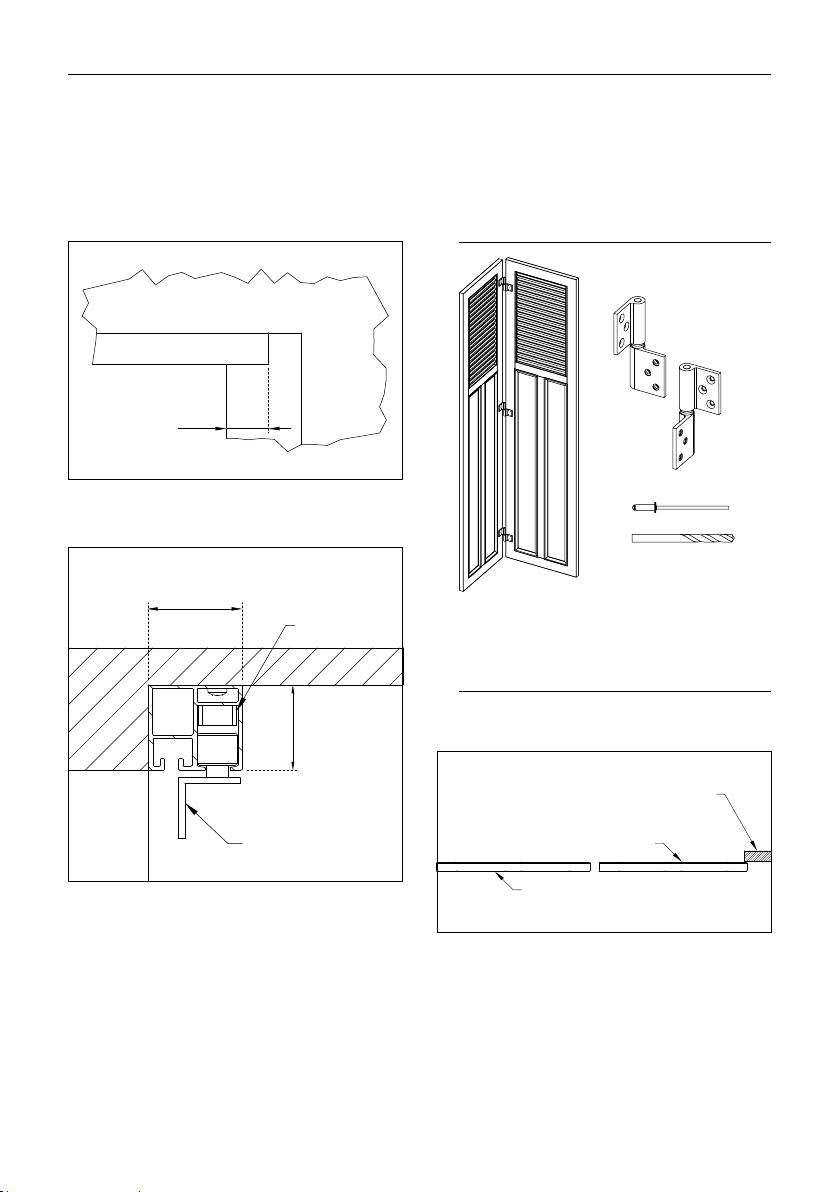
Scope of delivery
Contained in the scope of
delivery
Sashes
Hinges pre-installed
Guide
Hinges
Accessories
Guide rail
Guide can
be used left/
right
FSL-light hinge,
right
FSL-light
hinge, left

4,2 × 16 S1
9
1 Product description
INFO Fitting material to be provided by the customer!
Locking Tools required*
*not included in the scope of delivery
Masonry drill
Drill Ø 4.2 mm
Drill Ø 3.5 mm
WAF 3
Variant 1
Barrel bolt
FSL-light
Variant 2
Shutter holder
Shutter lock
Left Right
Pull handle

10
2 Installation instructions
Preparation
WARNING
Danger of injury and property damage
caused by unsuitable fitting materials
Select the fastening material in accordance
with the load capacity of the installation sub-
strates!
NOTES
• The selection of the fastening method is de-
pendent on the base and is therefore exclu-
sively your own responsibility.
• The installation material is not included in the
scope of delivery.
Check the scope of delivery for complete-
ness prior to installation.
Keep the guide rail, guides and barrel bolt
locking plates which will be required next on
hand.
Pre-drilling the guide rail
WARNING
Danger of injury and property damage
caused by falling folding sliding sashes
Fastening the guide rail inadequately can cause
the folding sliding sashes to fall.
Observe the maximum distances for the
mounting holes.
The distance between two mounting holes
must not exceed 400 mm!
CEILING INSTALLATION
100100
12
Befestigungsbohrung
Durchgangsbohrung
Befestigungsbohrungen Führungsschiene
2 Installation instructions

11
2 Installation instructions
WALL INSTALLATION
Important: If the drilling dimension for the first
two chambers is to be larger than Ø 9.7 mm,
the vertical dimension (15 mm) must be adap-
ted accordingly!
100 100
15*
Befestigungs-
bohrung
Bohrung Ø 9.7
Ø 9.7
Befestigungsbohrungen Führungsschiene
Mounting the guide rail
NOTES
The guide bracket can also be installed on the
outside.
Check whether the bracket can be installed
on the inside before installation.
Measure the guide rail.
Window opening cut-out
Guide rail
Window frames
View from outside
Insert the left/right guide and the barrel bolt
locking plate into the guide rail.
2.1
Sash front edge
Locking plate
Guide
right/left
12
2 Installation instructions
Keep a side projection of 56 mm on the
hinge side.
2.2
56
Align and fasten the guide rail.
2.3
46
42
Locking plate
Guide bracket
right/left
Installing the hinges on the sashes
Keep the sashes, hinges, N1 RIVETS and
Ø 4.2 mm drill on hand.
Position the access sash and the hinge sash.
The hinge sash is 20 mm wider than the ac-
cess sash!
2.4
Access sash
Hinge sash
Masonry
13
2 Installation instructions
Determine the installation heights of the
hinges.
2.5
5
5
5050
Sash upper edge
Upper edge
of top hinge
Sash lower edge
Lower edge
of bottom hinge
Hinge installation heightHinge installation height
Installation height: From the upper edge of the sash to
the upper edge of the hinge and from the lower edge of
the sash to the lower edge of the hinge
Position the hinges and fasten using N1
RIVETS.
2.6
5
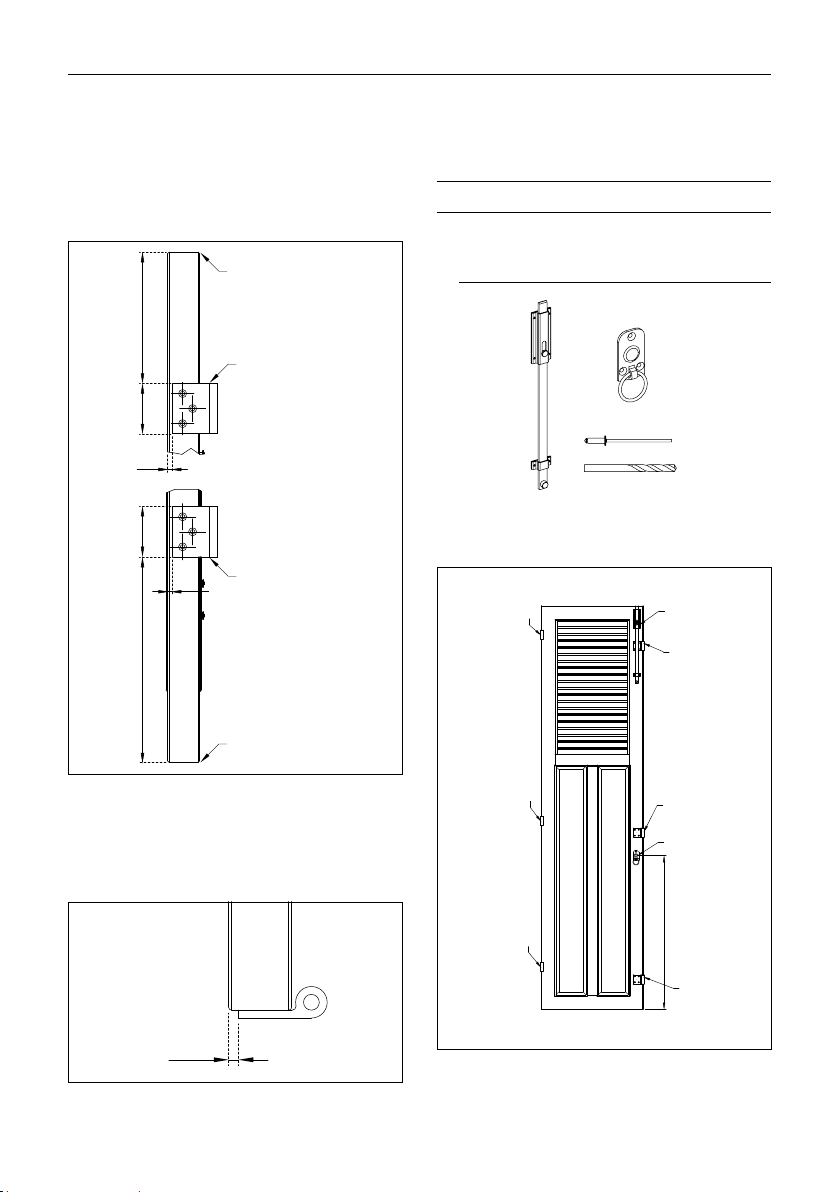
Installing the accessories on the
hinge sash
VARIANT 1+2
Keep the shutter lock, pull handle, N1 RIV-
ETS and Ø 4.2 mm drill on hand.
Determine the installation height of the pull
handle.
2.7
Shutter lock
Hinge
Hinge
Hinge
Hinge
Hinge
Pull handle
Hinge
Installation height
Installation height: Lower edge of sash to centre of pull
handle

14
2 Installation instructions
Position the shutter lock and fasten using
N1 RIVETS.
Do not forget the supports for the shutter
lock!
2.8
14
20
14
Supports for shutter lock
Position the pull handle and fasten using N1
RIVETS.
2.9
Distance dimension
Distance dimension from the centre of the pull handle to
the outer edge of the frame:
37.5 mm (for frame R75) / 24 mm (for frame R48);
or in the axis of the shutter lock
VARIANT 2
Determine the installation height of the
shutter holder
shutter holder
movable
Installation height
Installation height: Lower edge of sash to centre of shutter
holder
Position the shutter holder
Fasten the shutter holder with N1 rivets
and sleeves
The shutter holder is unlocked by means of
a lifting motion.
26
unlocking

15
2 Installation instructions
Installing the accessories on the
access sash
VARIANT 1
Keep the barrel bolt, N1 RIVETS and Ø4.2
mm drill on hand.
Access sash
Barrel bolt
View from inside
Position the barrel bolt and fasten using N1
RIVETS.
2.10
33
32
33
Remove the bolt knob.
Pull the locking rod out of the guide.
2.11
1.
2.

16
2 Installation instructions
VARIANT 2
Determine the installation height of the shut-
ter holder
shutter holder
fixed
installation height
Installation height: Lower edge of sash to centre of shutter
holder
Position the shutter holder
Fasten the shutter holder with N1 rivets
6
Installing the hinge sash
NOTES
• The selection of the fastening method is de-
pendent on the base and is therefore exclu-
sively your own responsibility.
• The installation material is not included in the
scope of delivery.
• The increased total weight of the pre-installed
sash packets can make the alignment of
sashes difficult during installation, depending
on the model and size.
Where appropriate, release the access
sash from the hinge sash.
Sash packet
Access sash
Hinge sash

17
2 Installation instructions
Position the hinge sash under the guide rail
and align it using a spirit level.
2.12
View from outside
Check the gap (7 mm) between the hinge
sash and the guide rail.
Hang the brackets on the hinge and screw
onto the base.
2.13
48
5
50
7
8 mm projection
Guide rail
Edge of
window
frame
Brackets
Hinge sash
Hinge installation
height
Check the sash again using a spirit level.
Fasten the lower hinge.
Hang the access sash and carry out a shut-
ting test.
Shutting test: Both sashes must be parallel
to the façade when closed!

18
2 Installation instructions
Setting the locking plate
VARIANTE 1
Keep S1 SCREWS and Ø 3.5 mm drill on
hand.
Place the sash packet in the desired opening
position.
Mark the locking plate.
The marked distance dimension of 65 mm
relates to an edge clearance of 56 mm and
applies exclusively to this measurement!
Locking plate
65
56
Sash opening position
2.14
81
Drill the locking plate.
Screw the locking plate in place using S1
SCREWS.
2.15
Locking plate

19
2 Installation instructions
Installing the guide
NOTES
The guide bracket can also be installed on the
outside.
Check whether the bracket can be installed
on the inside before installation.
KEEP N1 RIVETS and Ø 4.2 mm drill on
hand.
View from inside
Position the guide bracket on the corner of
the frame and fasten using N1 RIVETS.
2.16
Guide
Install the locking rod of the barrel bolt again.
2.17
Guide bracket

© 07.2018 EHRET GmbH | E 619.2 | This technical document includes information that is protected by copyright. All rights are re-
served. We reserve the right to make changes, including technical changes, in this document. This document has been prepared with
great care. Liability will not be assumed for any errors that might still exist and their consequences.
EHRET GmbH
Aluminium shutters
Bahnhofstrasse 14 - 18
77972 Mahlberg, Germany
Tel. + 49 (0) 78 22 /439 - 0
Fax + 49 (0) 78 22 /439 - 116
www.ehret.com
Table of contents
Other EHRET Indoor Furnishing manuals


Popular Indoor Furnishing manuals by other brands


Style selections
Style selections ACW08RUSLUV quick start guide

Naterial
Naterial IDAHO 2023R09P01-0025 instruction manual

porada
porada ABACUS Assembly instruction

Wall Bed Factory
Wall Bed Factory Mission Assembly instructions

IKEA
IKEA EKTORP CHAIR FRAME instructions

Vente Unique
Vente Unique AZIDEE-LHF Product description

Pacific Casual
Pacific Casual Caspian 14H051SEC-B1 Assembly instructions

DRAGONN
DRAGONN DN-CH-K01B instruction manual

J GEIGER
J GEIGER inception shades installation guide

Otto
Otto 83941134 Assembly instructions

Songmics
Songmics ULPB57 Assembly manual

ADA Trendline
ADA Trendline Nadina Comfort Assembly instruction