EHRET VOLETRONIC User manual

Operating instructions
INSTALLATION
SPECIALIST PERSONNEL
Valid from 09.2011
E 917.2
VOLETRONIC
Motorisation for sliding shutters
2
Notes
The present operating instructions describe
the commissioning & programming of EHRET
sliding shutter drive VOLETRONIC.
It is essential to install the sliding shutter sys-
tem in accordance with the specifications laid
out in the E915 Installation instructions
EHRET sliding shutters before commissioning
the sliding shutter control.
Carefully read through these instructions prior
to commissioning. Observe the specified pro-
cess steps and take into account the notes and
recommendations given. Knowledge of and
technically impeccable implementation of the
given safety notes and warnings are prerequi-
sites for safe and proper operation of the
EHRET sliding shutter control. Insufficient
knowledge at the time of commissioning and
utilisation lead to the loss of any liability claims
against EHRET GmbH. Installation and/or oper-
ation in full or partial deviation from our installa-
tion and operating instructions will lead to the
warranty for defects becoming void.
Installation instructions
INSTALLATION BY
SPECIALIST P ERSONNEL
Valid from 09.2011
E 915.5
Sliding shutters
Aluminium shutters
E 915 Installation instructions | EHRET Sliding shutters
These operating and maintenance instructions
are a component part of the product and are
therefore always to be retained until the prod-
uct is disposed of. These operating and main-
tenance instructions are to be passed along in
the event of the sale of this product.
These instructions are addressed to qualifi ed
specialist personnel. Qualified specialist per-
sonnel are persons who are familiar with the
transport, setup, installation, commissioning
and operation of the product and who have ap-
propriate qualifications for their work. Specia-
list personnel must know and observe the rele-
vant standards and/or guidelines.
This product is in accordance with general ru-
les of technology. Safety-conscious behaviour
is necessary for undertaking safe commissio-
ning. Observe for that reason the following no-
tes. Should you not understand something in
these Installation & operating instructions un-
ambiguously, do not fail to contact the specia-
list personnel at EHRET GmbH, 77972 Mahl-
berg (Germany).
Bore hole sizes and fastening material are re-
commendations; these could vary because of
the substrate!

3
Contents
Notes. . . . . . . . . . . . . . . . . . . . . . . . . . . . . . . . . . . . . . . . . . . . . . . . .2
Explanation of signs and symbols . . . . . . . . . . . . . . . . . . . . . . . . . . . . . . . . . .4
Safety notes . . . . . . . . . . . . . . . . . . . . . . . . . . . . . . . . . . . . . . . . . . . . . 4
Electrical installation . . . . . . . . . . . . . . . . . . . . . . . . . . . . . . . . . . . . . . . . . 6
Incorrect operation. . . . . . . . . . . . . . . . . . . . . . . . . . . . . . . . . . . . . . . . . .7
Behavior at power breakdown . . . . . . . . . . . . . . . . . . . . . . . . . . . . . . . . . . . .7
Disposal . . . . . . . . . . . . . . . . . . . . . . . . . . . . . . . . . . . . . . . . . . . . . . . 8
EC Declaration of Conformity . . . . . . . . . . . . . . . . . . . . . . . . . . . . . . . . . . 9
A VOLETRONIC 230 V | serial push-button operation
Product description . . . . . . . . . . . . . . . . . . . . . . . . . . . . . . . . . . . . . . 10
Connection. . . . . . . . . . . . . . . . . . . . . . . . . . . . . . . . . . . . . . . . . . . 11
Commissioning . . . . . . . . . . . . . . . . . . . . . . . . . . . . . . . . . . . . . . . . 12
Setting the running direction . . . . . . . . . . . . . . . . . . . . . . . . . . . . . . . . . 13
Executing a learning run . . . . . . . . . . . . . . . . . . . . . . . . . . . . . . . . . . . . 14
Setting the speed . . . . . . . . . . . . . . . . . . . . . . . . . . . . . . . . . . . . . . . 15
Impulse/dead man mode . . . . . . . . . . . . . . . . . . . . . . . . . . . . . . . . . . . 16
B VOLETRONIC 230 V | wireless remote control
Product description . . . . . . . . . . . . . . . . . . . . . . . . . . . . . . . . . . . . . . 18
Connection. . . . . . . . . . . . . . . . . . . . . . . . . . . . . . . . . . . . . . . . . . . 19
Commissioning . . . . . . . . . . . . . . . . . . . . . . . . . . . . . . . . . . . . . . . . 20
Teaching master transmitter. . . . . . . . . . . . . . . . . . . . . . . . . . . . . . . . . . 21
Checking/Changing the running direction . . . . . . . . . . . . . . . . . . . . . . . . . . . 22
Performing a learning run . . . . . . . . . . . . . . . . . . . . . . . . . . . . . . . . . . . 23
Setting the speed . . . . . . . . . . . . . . . . . . . . . . . . . . . . . . . . . . . . . . . 24
Teaching an additional transmitter. . . . . . . . . . . . . . . . . . . . . . . . . . . . . . . 25
Clearing of an additionally taught transmitter . . . . . . . . . . . . . . . . . . . . . . . . . 26
Global clearing of all additionally taught transmitters . . . . . . . . . . . . . . . . . . . . . 27
Group control . . . . . . . . . . . . . . . . . . . . . . . . . . . . . . . . . . . . . . . . . 28
C VOLETRONIC Solar 12 V | wireless remote control
Product description . . . . . . . . . . . . . . . . . . . . . . . . . . . . . . . . . . . . . . 30
Connection. . . . . . . . . . . . . . . . . . . . . . . . . . . . . . . . . . . . . . . . . . . 31
Attach solar panel on the cover . . . . . . . . . . . . . . . . . . . . . . . . . . . . . . . . 32
Attaching the rechargeable battery . . . . . . . . . . . . . . . . . . . . . . . . . . . . . . 33
Commissioning . . . . . . . . . . . . . . . . . . . . . . . . . . . . . . . . . . . . . . . . 34
Teaching master transmitter. . . . . . . . . . . . . . . . . . . . . . . . . . . . . . . . . . 36
Monitoring/modification of the direction of travel. . . . . . . . . . . . . . . . . . . . . . . 37
Further settings . . . . . . . . . . . . . . . . . . . . . . . . . . . . . . . . . . . . . . . . 38
Troubleshooting . . . . . . . . . . . . . . . . . . . . . . . . . . . . . . . . . . . . . . . . . . 39
4
Important notes
Explanation of signs and symbols
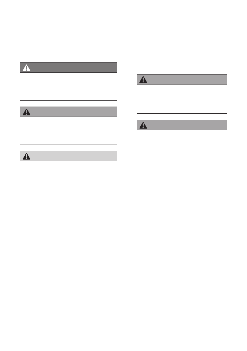
Warning notes
DANGER
Designates an imminent danger that
could lead to death or severe injuries if
the respective precautionary measures
are not implemented.
WARNING
Means that death, severe bodily injury or
major property damage could occur if the
respective precautionary measures are
not implemented.
CAUTION
Means a possible danger that could lead
to minor injuries or property damage if it
is not avoided.
Directives for action
Safety notes
Only qualified specialist personnel may
carry out installation and commission-
ing!
WARNING
Incorrect installation could lead to se-
vere injuries and/or damage to prop-
erty.
Follow all installation instructions.
WARNING
Take into account the following notes
and warnings in order to avoid dangers
and to protect the product.
Observe the accident prevention regula-
tions of the Accident Prevention & Insur-
ance Association.
Observe the rules of the road during trans-
port.
Make sure that the load is well-secured on
the means of transport.
Take care to ensure that the drives are
stored under dry conditions prior to final in-
stallation and commissioning.
Cordon off a generously large area around
the installation site.
Observe without limitation the regulations
of the manufacturers of dowel and attach-
ment materials.
The mounting bases of the installation site
are to be checked for load-bearing capacity
prior to installation.
In the event of uncertainties about the
mounting bases, contact your responsible
building experts.
Electrical work may be carried out only by
authorised electricians.

5
Important notes
The specified connection diagrams are to
be observed, as otherwise damage to the
motor could occur. EHRET GmbH assumes
no liability for damage resulting from incor-
rect installation.
Check the product for damage prior to in-
stallation. Products requiring repair may not
be used.
Do not touch any internal parts of the prod-
uct that become exposed as the result of
damage (e.g. electrical cables/lines).
Discontinue operation of your electrical
drive at once in the event of smoke or
fumes.
Do not allow children to play with the oper-
ating apparatus of the drives.
Electrical/electronic devices are not secure
against failure. Make sure that no hazard-
ous situations for personnel or product
could arise in the event of a power failure.
Devices with electrical controls could go
into motion at any time and without warn-
ing. Prevent situations hazardous to person-
nel and product that arise from this fact.
No personnel or obstacles are permitted to
be within the range of pivoting and/or trav-
elling shutters while they are moving. Keep
personnel and objects away until the shut-
ters have reached their final position.
Do not reach into moving parts or closing
areas while shutters are opening or closing.
Make sure that no articles of clothing or
body parts are able to be caught by moving
parts in the system.
Disconnect the drives from the power sup-
ply during maintenance work.
Ice could form on the product in the event
of snowfall, sleet or icy rain. Do not operate
equipment until the ice formation is no
longer present, and switch automatic con-
trols to manual.
Make sure that the shutters are locked be-
fore any wind load occurs.
The shutters may not be operated at wind
speeds from 62 km/h (stormy wind).
No additional loads such as persons or ob-
jects are permitted to have an effect on the
shutters.
Shutters are not intended to protect indi-
viduals from falls.
WARNING
Danger of injury from the weight of
the product!
Due to the weight of the products,
perform transport and installation by at
least two individuals.
Transport the product carefully in order to
avoid damage.
Take care to ensure that the product is not
damaged when the packaging material is
removed.
WARNING
Danger of suffocation from packaging
foil.
The packaging foil must be kept out of
reach of children.
Store the foil carefully until you turn it
in for recycling.
Turn the packaging materials in for recy-
cling.

6
Important notes
Electrical installation
DANGER
Electrical shock (230 V)
The correct installation of the sliding shut-
ter drive may be carried out only by autho-
rised specialist personnel!
At the time of installation, all connections,
as shown schematically in the illustration,
are to be connected. The guarantee ex-
pires if the Hirschmann plug is removed.
The connection (Phase L) must be equip-
ped with a line safety switch with a maxi-
mum nominal current of 6 A.
The line safety switch must have a switch-
off capacity of at least 6 kA.
The prescribed tripping characteristic is B.
The line switch should be equipped with a
thermal tripping device for overload protec-
tion, furthermore it should have an electro-
magnetic trigger as a protection against
short circuits.
Other requirements may apply to the instal-
lation of the line safety switch, depending
on the location. For example, it could be
necessary to use a line safety switch with
additional separation of Phase N in order to
switch off all poles. It might possibly also be
necessary to have a residual current circuit
breaker in the system. The standards and
the laws of the respective country with res-
pect to permanent electrical installations
are to be complied with (e.g. VDE 0100).
It is recommended that no more than fi ve
drives are secured simultaneously by a sin-
gle line safety switch.
Pursuant to VDE 0100 and/or the statutory
regulations and standards of the respective
country, the permanent electrical installati-
on must be carried out by a certified electri-
cian.
According to VDE 0022, the operator and
the installer are responsible for compliance
with the VDE regulations and/or regulations
of the energy supplier.
7
Important notes
Incorrect operation
Correct operation can no longer be ensured if
the sliding shutter is moved by hand quickly
and with great force in its position, and not by
means of operation with the OPEN- or
CLOSE-button.
A force may be applied to the sliding shutter in
such cases in such a way that the current me-
chanical position of the sliding shutter no lon-
ger matches the position present in the con-
trol.
This leads to incorrect information within the
control, as a result of which the control will no
longer function correctly.
This condition usually is rectified by an as-
cent and descent run.
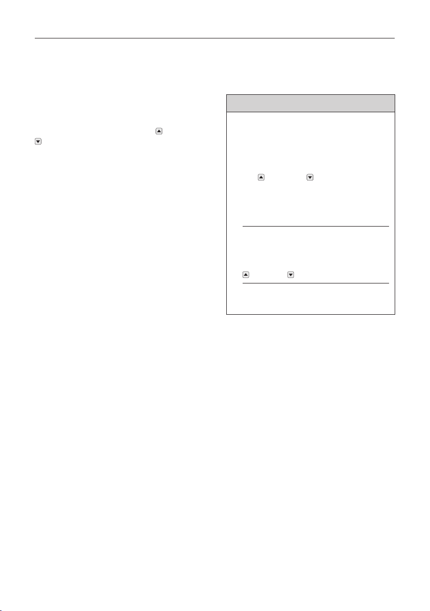
Behavior at power breakdown
IMPORTANT
Deletion of reference position due to po-
wer failure
Power failure can lead to deletion of the re-
ference position.
Move the sliding shutter with push-but-
ton OPEN- or CLOSE in direction
of motor to until the end position. In
this position the control system recog-
nize the reference of the normal wor-
king.
If the sliding shutter has been in position
of reference, at power breakdown, it is
necessary to have to move the shutter
for and backward with push-button
OPEN- or CLOSE.
After that the function is again guaran-
teed.
8
Important notes
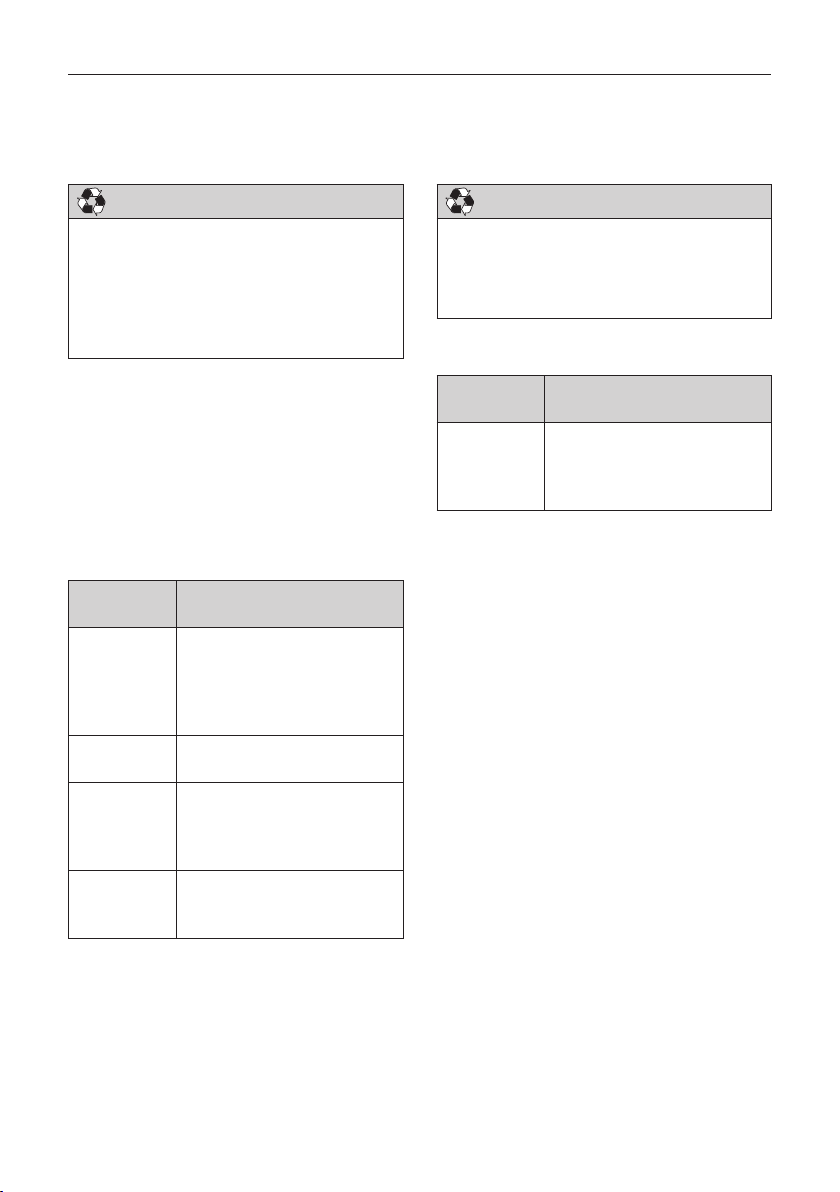
Disposal
IMPORTANT
Disposal
• The following information must be strictly
adhered to in order to prevent any environ-
mental damage. Even if the machine is dis-
posed of by certified experts, the operator
must ensure proper execution!
Some materials of the machine are reusable.
By recycling some parts or raw materials from
used products, you make an important contri-
bution to protecting the environment.
Please contact your local authorities if you
require information about collection points
near you.
Recyclable materials of the machine
Reusable
material
Components
Aluminium • Sliding shutters
• Suspensions
• Guide brackets
• Window sill cover
• Fittings
Copper • Cables
• Motor
Plastic,
rubber, PVC
• Guides
• Accessories
• Seals
• Cables
Steel • Motor and components
• Fittings
• Accessories
IMPORTANT
Disposal
Dispose of any machine parts in such a
way that damage to human health and the
environment can be excluded.
Hazardous waste
Reusable
material
Components
Electronic
waste
• Electrical supplies
• Control units
• Circuit boards with
electronic components

9
Important notes
EC Declaration of Conformity
The manufacturer: EHRET GmbH
Aluminium Shutters
Bahnhofstrasse 14 - 18
D - 77972 Mahlberg
erklärt für das Produkt: VOLETRONIC 230 V sliding shutter drive
VOLETRONIC Solar 12 V sliding shutter drive
to which this guideline refers, is in conformance with the stipulations of
Guideline 1999/05/EC Radio equipment and telecommunications terminal equipment
as well as with the following standards:
EN 301 489-3:2000 Electromagnetic compatibility and Radio spectrum Matters
(ERM), Electromagnetic Compatibility (EMC) standard for radio
equipment and services – Part 3: Specific conditions for Short-
Range Devices (SRD) operating on frequencies between 9 kHz
and 40 GHz
EN 300 220-3:2000 Electromagnetic compatibility and Radio spectrum Matters
(ERM); Short Range Devices (SRD) radio equipment to be used
in the 25 MHz to 1000 MHz frequency range with power levels
ranging up to 500 mW – Part 3: Harmonized EN covering essen-
tial requirements under Article 3.2 of the R&TTE Directive
98/37/EC Machinery Directive
EN 73/23/EEC Low Voltage Directive
EN 60730 +A1 +A2 +A11 Safety requirements for automatic electric regulators and
+A12+A13+A14+A15 controllers
—
Name and address of the individual who is authorised to assemble the technical documentation:
Ralf Gielen Location: 77972 Mahlberg, Germany
Head of Technology Date: 01/01/2015
EHRET GmbH
Andreas Schnaase
Head of Sales
EHRET GmbH
Eberhard Schopferer
Management
10
AVOLETRONIC 230 V | serial push-button operation
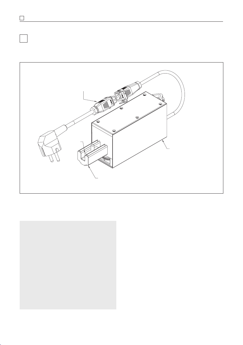
A VOLETRONIC 230 V | serial push-button operation
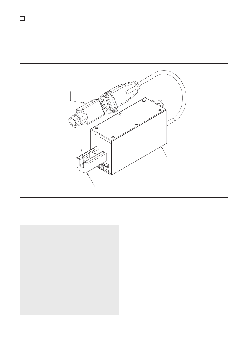
Product description
Rail connection
Motor cover
Rail clamp
Connection cable
with 5-pin Hirschmann plug
Technical data
Power supply 85 VAC–265 VAC,
50/60Hz, 30 W
Standby < 1 W
Protection class I
IP type of protection IP 43
Temperature range – 20° C to + 60° C
in operation
Speed max. 120 mm/s
Propulsion max. 150 N
Connection cable 5-pin Hirschmann
plug
Power input of the < 5 mA (1 W)
Close/Open entrance
The EHRET VOLETRONIC 230 V sliding shutter
drive is a drive with integrated control for the
actuation of sliding shutters.
• Congurable running speed
• Electronic locking in end position
• Programming of the pick-up position of dou-
ble bars and acceleration or delay of the run-
ning speed at the beginning, the end and in
the pick-up range.
• Creep travel upon reaching the start and end
position
11
VOLETRONIC 230 V | serial push-button operation A
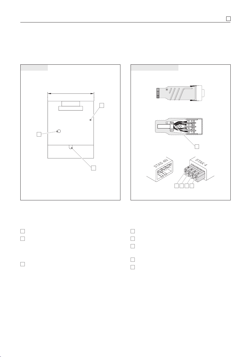
Connection
B
C
A
ca. 55
Motor housing
Motor
AMotor cover
BMains connection 230 V with Hirschmann
coupling, 5-pin. The motor is equipped with
a 5-pin connection cable with Hirschmann
coupling approx. 0.5 m.
CMonitoring LED on the side of the motor
housing (green | yellow | red) used for exam-
ple for checking the running direction.
4
3
2
1
4
3
2
1
0
4321
Connection cable with plug
5-pin Hirschmann plug
0Earth – protective conductor (green/yellow)
1Mains connection, L-Phase (230V)
2Mains connection N-neutral conductor
(230V)
3OFF-button signal (230V)
4ON-button signal (230V)
12
AVOLETRONIC 230 V | serial push-button operation
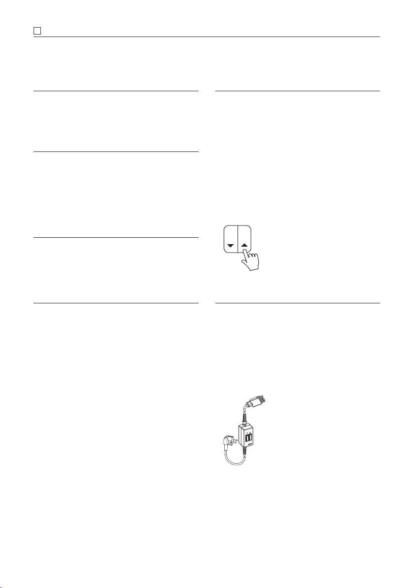
Commissioning
NOTE
• The correct installation of the sliding shutter
drive may be carried out only by authorised
specialist personnel; it is only then that the
entire functionality can be guaranteed.
Initial commissioning can be carried out once
the motor has been correctly installed in the
sliding shutter system.
Connect the 5-wire Hirschmann coupling to
your serial push-button and your electrical cir-
cuit!
Check the running direction
If the running direction is correctly set, then the
LED display on the motor will light up green
during ascent and red during descent.
If this is not the case, then the running direction
must be changed (see chapter “Setting the
running direction”, page 13).
SERIAL PUSH-BUTTON
• In order to avoid an unwanted change of pa-
rameters, the time (max. 2 sec.) between the
individual programming steps must be ob-
served.
• The signal tones must have gone out before
the next programming step.
• Always check the running direction after a
change of parameters. It is displayed accord-
ingly through the LED on the drive housing
with green for ascent, red for descent
and yellow during the learning run.
MOTOR SETTING & INSPECTION UNIT
• As an optional alternative to the serial push-
button, the motor can also be tuned through
the “motor setting & inspection unit V3,
5-wire”, art. no. 881057.
• If no connector is available at the time of the
installation, then the motor setting & inspec-
tion unit must be used.
13
VOLETRONIC 230 V | serial push-button operation A
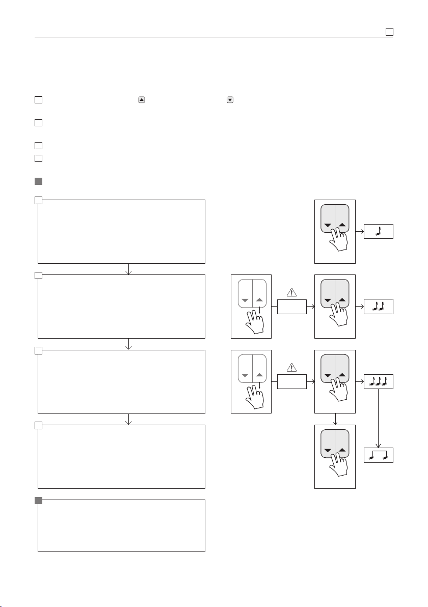
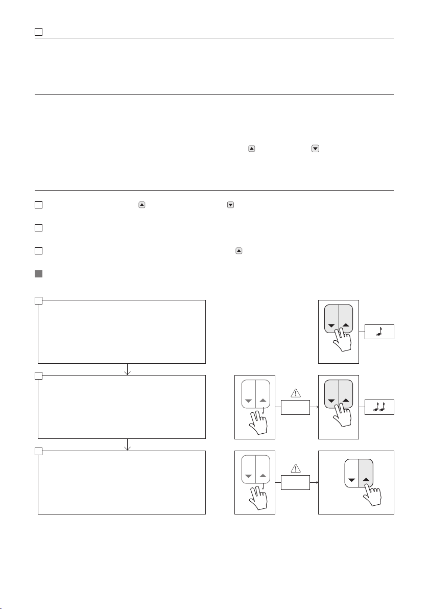
Setting the running direction
1Press and hold down the OPEN button and the CLOSE button together and simultaneously
(approx. 3 sec.), until a brief signal tone is heard and then goes out.
2Release the buttons only briefly, then, within a maximum of 2 seconds, press and hold them
down simultaneously again until the following 2 signal tones go out.
3Release the buttons briefly again and then repeat the procedure once more.
4However, after the sounding of the 3 signal tones, do not release the buttons until a longer sig-
nal tone is heard and goes out. The running direction is thus changed.
Check the running direction through LED check.
Hold OPEN + CLOSE button pressed down for
approximately 3 sec.
1 signal tone
Release OPEN + CLOSE button
Press and hold OPEN + CLOSE button down once
more within 2 sec. for approx. 3 sec.
2 signal tone
2
Release OPEN + CLOSE button
Press and hold OPEN + CLOSE button down once
more within 2 sec. for approx. 3 sec.
3 signal tone
3
Continue to hold OPEN + CLOSE button pressed
down until
Long signal tone
the running direction is changed
4
≤ 2 sec.
≤ 2 sec.
1
Check the running direction
If the running direction is correct, the LED will show:
green at ASCENT
red at DESCENT
14
AVOLETRONIC 230 V | serial push-button operation
Executing a learning run
NOTES
Systems with double bars (a sash that is not connected with the drive cable)
The double bars must be manually taught during the learning run:
Move sashes into the Open end position
As soon as the powered sash moves the double bar, the OPEN and the CLOSE button must
be actuated briefly and simultaneously. A signal tone confirms the programming.
This procedure must be repeated in the case of systems with several double bars (max. 4). Each
manual actuation of an additional double bar is acknowledged with an additional signal tone.
1Press and hold down the OPEN button and the CLOSE button together and simultaneously
(approx. 3 sec.), until a brief signal tone is heard and then goes out.
2Release the buttons only briefly, then press and hold them down together again once more until
the following 2 signal tones go out.
3After the second signal tone, immediately press the OPEN button 3× in quick succession. The
learning run starts automatically.
LED monitoring: When the learning run is correct, the LED on the drive lights up yellow and ends
with a twotime signal tone.
≤ 2 sec.
3×
≤ 2 sec.
Hold OPEN + CLOSE button pressed down for
approximately 3 sec.
1 signal tone
Release OPEN + CLOSE button
Press and hold OPEN + CLOSE button down once
more within 2 sec. for approx. 3 sec.
2 signal tone
Release OPEN + CLOSE button
Press the OPEN button within 2 sec. 3× in quick
succession
Learning run starts automatically
1
2
3
15
VOLETRONIC 230 V | serial push-button operation A
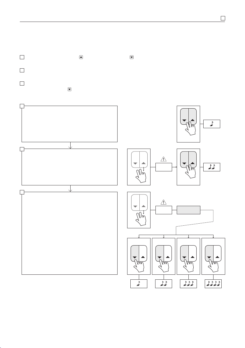
Setting the speed
1Press and hold down the OPEN button and the CLOSE button together and simultaneously
(approx. 3 sec.), until a brief signal tone is heard and then goes out.
2Release the buttons only briefly, then press and hold them down together again once more until
the following 2 signal tones go out.
3Release the buttons and then select the desired speed level (max. 4 levels) by repeatedly and
briefly pressing the CLOSE button. The respective speed level is displayed accordingly by the
number of signal tones.
1×
≤ 2 sec.
≤ 2 sec. Levels 1–4
2× 3× 4×
Hold OPEN + CLOSE button pressed down for
approximately 3 sec.
1 signal tone
Release OPEN + CLOSE button
Press and hold OPEN + CLOSE button down once
more within 2 sec. for approx. 3 sec.
2 signal tone
Release OPEN + CLOSE button
select the speed level within 2 sec.
1× pressing CLOSE button = speed level 1
2× pressing CLOSE button = speed level 2
3× pressing CLOSE button = speed level 3
4× pressing CLOSE button = speed level 4
1
2
3

16
AVOLETRONIC 230 V | serial push-button operation
Impulse/dead man mode
1Press and hold down the OPEN button and the CLOSE button together and simultaneously
(approx. 3 sec.), until a brief signal tone is heard and then goes out.
2Release the buttons only briefly, then press and hold them down together again once more until
the following 2 signal tones go out.
3Repeat this procedure until 3 signal tones are heard and go out.
Repeat this procedure until 4 signal tones are heard and go out. However, after the fourth signal
tone sounds, continue to hold the OPEN button and the CLOSE button pressed down until
a brief signal tone confirms impulse mode, or a long signal tone confirms dead man mode.
Hold OPEN + CLOSE button pressed down for
approximately 3 sec.
1 signal tone
Release OPEN + CLOSE button
Press and hold OPEN + CLOSE button down once
more within 2 sec. for approx. 3 sec.
2 signal tones
Release OPEN + CLOSE button
Press and hold OPEN + CLOSE button down once
more within 2 sec. for approx. 3 sec.
3 signal tones
Release OPEN + CLOSE button
Press and hold OPEN + CLOSE button down once
more within 2 sec. for approx. 3 sec.
4 signal tones
Continue to hold OPEN + CLOSE button pressed
down until:
Long signal tone = dead man mode
Short signal tone = impulse mode
≤ 2 sec.
≤ 2 sec.
≤ 2 sec.
1
2
3

17
18
BVOLETRONIC 230 V | wireless remote control
B VOLETRONIC 230 V | wireless remote control
Product description
Rail connection
Motor cover
Rail
clamp
Connection cable
with 3-pin Hirschmann plug
Technical data
Power supply 85 VAC–265 VAC,
50/60Hz, 30 W
Standby < 1 W
Protection class I
IP type of protection IP 43
Temperature range – 20° C to + 60° C
in operation
Speed max. 120 mm/s
Propulsion max. 150 N
Connection cable 3-pin Hirschmann
plug
Power input of the < 5 mA (1 W)
Close/Open entrance
The VOLETRONIC sliding shutter drive with
wireless remote control is a drive with integrat-
ed control for the actuation of sliding shutters.
• Congurable running speed
• Electronic locking in end position
• Programming of the pick-up position of dou-
ble bars and acceleration or delay of the run-
ning speed at the beginning, the end and in
the pick-up range.
• Creep travel upon reaching the start and end
position

19
VOLETRONIC 230 V | wireless remote control B
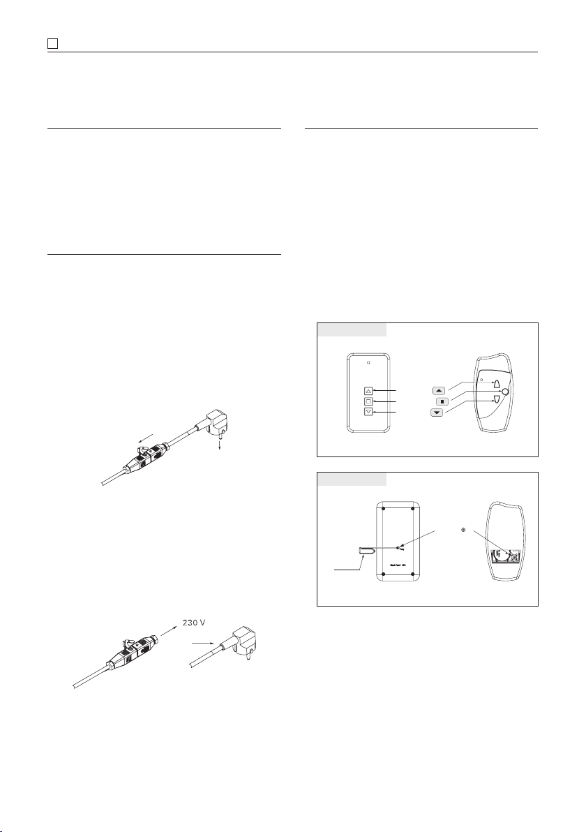
Connection
B
C
A
ca. 55
D
Motor housing
Motor
AMotor cover
B230 V mains connection with Hirschmann
coupling. The motor is equipped with a 3-pin
connection cable with Hirschmann coupling
approx. 0.5 m.
CMonitoring LED on the side of the motor
housing (green | yellow | red) used for exam-
ple for checking the running direction
DAntenne 868 MHz
• Connected shock-proof plug for setup and
programming of the system by the installer.
• Hirschmann plug (must be connected to the
electrical circuit by an electrician)
2
1
0
1
2
1
2
Connection cable with plug
3-pin Hirschmann-plug
0Earth – protective conductor (green/yellow)
1Mains connection L – Phase (230 V)
2Mains connection N – Neutral conductor
(230 V)
20
BVOLETRONIC 230 V | wireless remote control
Commissioning
NOTES
• The correct installation of the sliding shutter
drive may be carried out only by authorised
specialist personnel; it is only then that the
entire functionality can be guaranteed.
INITIAL COMMISSIONING
A) Installer (optional)
The shock-proof plug is used to supply current
to the drive for optional first-time commission-
ing by the installer or in the absence of an elec-
trical supply line at the building site.
If necessary, connect it to the Hirschmann
coupling and to an electrical outlet.
B) Electrical permanent installation
Remove the shock-proof plug and connect
the 3-wire Hirschmann coupling to your elec-
trical circuit. Do not remove the Hirschmann
coupling while doing so!
WIRELESS REMOTE CONTROL
In order to avoid an unwanted change of pa-
rameters, the time (max. 2 sec.) between the
individual programming steps must be ob-
served.
The signal tones must have gone out before
the next programming step.
Always check the running direction after a
change of parameters! It is displayed accord-
ingly through the LED on the drive housing
with green for ascent, red for descent
and yellow during the learning run.
Black Pearl HSN
OPEN
STOP
CLOSE
transmitter front
Black Pearl HSN
PROG
Paper
clip
transmitter back
Table of contents
Other EHRET Indoor Furnishing manuals


Popular Indoor Furnishing manuals by other brands

Costway
Costway JV10651 Instruction booklet

Next
Next 227884 Assembly instructions

Balzar Beskow
Balzar Beskow B-50 Assembly instructions

VERTBAUDET
VERTBAUDET 1062793 manual

Furniture of America
Furniture of America Kristie CM3314T-5PK Assembly instructions

AlfrescoPlus
AlfrescoPlus APSFM Assembly instructions


