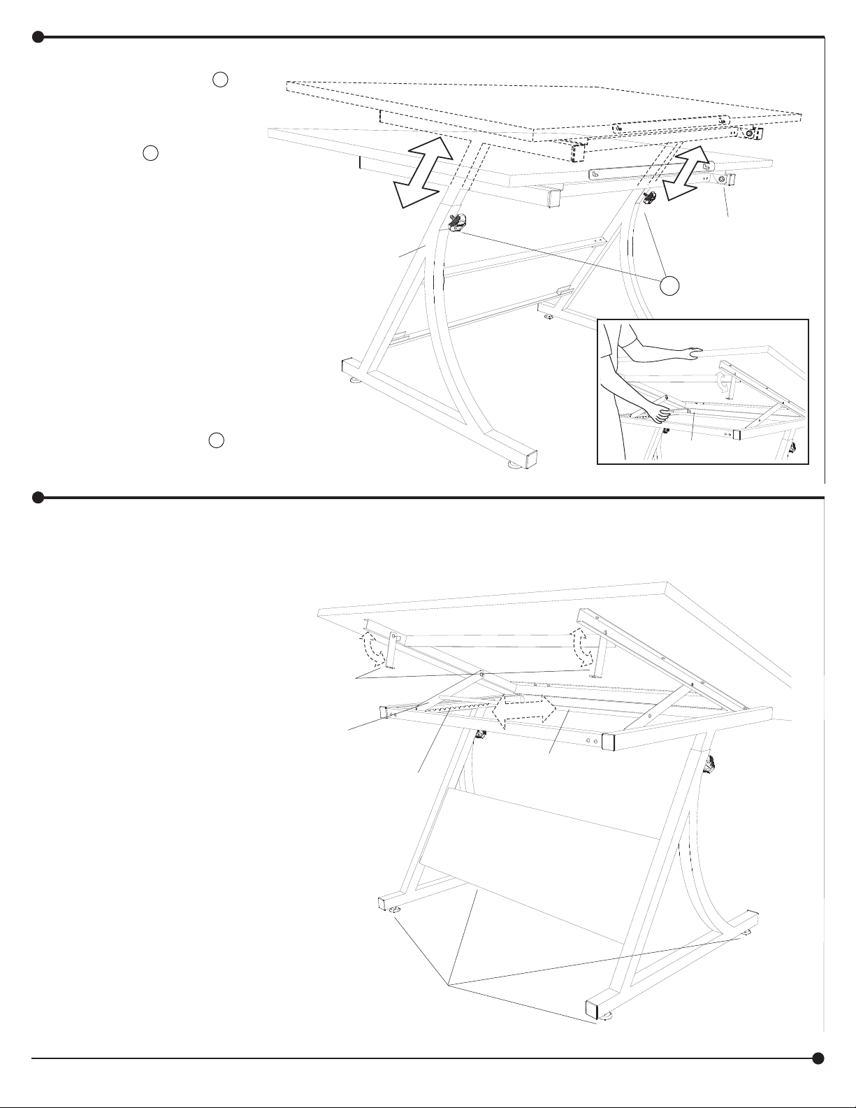
Safco Plan Master User manual
Other Safco Indoor Furnishing manuals

Safco
Safco facil 4971 User manual

Safco
Safco 5060 User manual

Safco
Safco 1705 User manual

Safco
Safco TASK MASTER User manual

Safco
Safco Priya 5075 User manual

Safco
Safco Diaz 4194 User manual

Safco
Safco 3436 User manual

Safco
Safco Vue 3397 User manual

Safco
Safco AlphaBetter 1203 User manual

Safco
Safco 7500 User manual

Safco
Safco Forge 7990 User manual

Safco
Safco Task Mater 5124 User manual

Safco
Safco 1208 User manual

Safco
Safco Value Sorter 7121 User manual

Safco
Safco 7751 User manual

Safco
Safco Luxe 4134 User manual

Safco
Safco 9452 User manual

Safco
Safco 1706 User manual

Safco
Safco 2196 User manual

Safco
Safco Scoot 1601 User manual


Popular Indoor Furnishing manuals by other brands


Coaster
Coaster 4799N Assembly instructions

Stor-It-All
Stor-It-All WS39MP Assembly/installation instructions

Lexicon
Lexicon 194840161868 Assembly instruction

Next
Next AMELIA NEW 462947 Assembly instructions

impekk
impekk Manual II Assembly And Instructions

Elements
Elements Ember Nightstand CEB700NSE Assembly instructions