Eilon Engineering RON 2000 User manual

RON 2000 DYNAMOMETER / CRANE SCALE
Eilon Engineering Weighing Systems Ltd.
Instruction Manual
Version 4.2
Generation
4

_NV Ron 2000 4.2 i of 37 3/25/2016
U S E R ' S G U I D E A N D I N S T R U C T I O N M A N U A L F O R
TheRon2000
Shackle Type Hook Type
Eilon Engineering Industrial Weighing Systems Ltd.
Phone 866.669.6122 • Web www.eilon-engineering.com
E-mail: info@eilon-engineering.com
* Shackles not included on
Shackle Type systems
* Shackle and Hook included
on hook type systems

_NV Ron 2000 4.2 ii of 37 3/25/2016
TableofContents
General Cautions and Warnings .............................................. 1
IMPORTANT:..................................................................................3
Eilon Engineering Limited Warranty......................................... 4
1. General Description.............................................................. 5
2. Operation............................................................................. 7
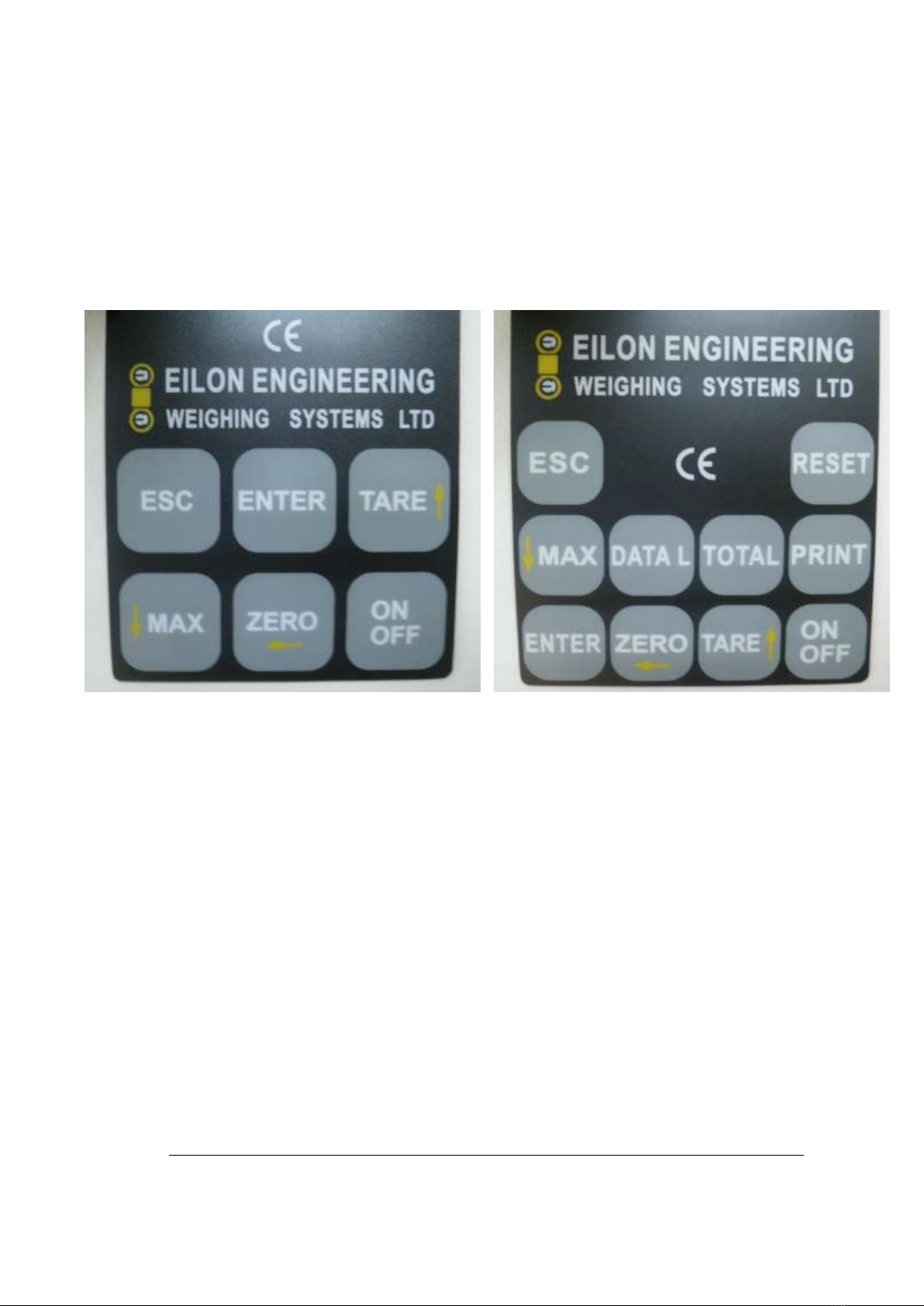
General operation of the keyboard:.................................................8
3. Tare...................................................................................... 8
4. Max (a.k.a. Peak Hold)......................................................... 9
5. Overload Warnings............................................................. 10
6. Power Saving Mode........................................................... 10
7. Battery Care....................................................................... 11
WARNING..................................................................................... 12
8. Calibration.......................................................................... 13
BEST PRACTICE .........................................................................13
9. Options............................................................................... 14
9.1 Set Points - Adjusting & General Scheme (if included)...........15
9.2 Units, user selectable (if included) ..........................................16
9.3 Time - setting the real time clock (if included)......................... 16
9.4 RS-232 Digital Output Communication Data (if included) .......17
9.5 Print, Mode Selection (only if the system is equipped with the
RS-232 output)..............................................................................20
9.6 Baud Rate Selection (if included)............................................21
9.7 Analog Output.........................................................................21
9.8 Totalizer with Data Logging (if included).................................22
9.9 Data Logger, standard (manual) (if included).......................... 23
9.10 Automatic Data Logger (if included)......................................25
9.11 Dynamic Data Logger (if Included)…………………………….26
9.12 Multiple Wire Rope Falls Option (if included) ........................ 27
Best Practice................................................................................. 27
9.13 Dampened Reading aka Averaging (if included)................... 27
9.14 Connector Cables (if included)..............................................28
10. Troubleshooting ............................................................... 30
11. Error Table....................................................................... 32
12. Suitable Shackles............................................................. 33
Index...................................................................................... 34

_NV Ron 2000 4.2 1/37 3/25/2016
GeneralCautionsand
Warnings
The following cautions and warnings, system specifications, and user
instruction sheets should be read carefully before attempting to use this Eilon
Engineering product.
Products are supplied with the express understanding that the purchaser
and/or user are thoroughly familiar with their correct application and proper
use. Eilon Engineering will assume no responsibility for the misuse or
misapplication of any of its products.
In addition to these guidelines, the user must also comply with general safe
operating practices when using the system e.g. when weighing during lifting.
The load limit rating, a.k.a. capacity, indicates the maximum force or load a
system can carry under normal working conditions. Overloading or placing a
load on the system above its rated capacity is dangerous and is therefore
STRICTLY PROHIBITED except during the system's annual safety testing.
This testing must be performed by qualified personnel and allows the system to
be overloaded up to 25% of its rated capacity, no more than once per year.
Eilon Engineering will accept no liability for damage caused by the product
being used in excess of the working load limit or from abuse.
Opening, attempting to open, or any attempt to repair the system by
unauthorized personnel (without written authorization) will nullify the warranty
as well as the manufacturer's liability and could be dangerous. Refrain from
doing so and contact an Elion representative should any problem with the
system arise.
When measuring loads using a shifted zero with the tare function, the actual load
is the value indicated on the readout plus that of the shifted zero or tare.
The system is designed for static loading. Eilon Engineering or other qualified
engineering personnel should be consulted before using the system to measure
dynamic loads.

_NV Ron 2000 4.2 2/37 3/25/2016
Avoid bending, twisting, side loading and off-axis loading.
When connecting the load cell in order to measure forces or loads, special care
should be taken in choosing appropriate shackles or other connecting
accessories that will permit free movement and prevent bending moments and
twisting in the load cell.
Always use shackles with a S.W.L. (Safe Working Load) equal to, or greater than
the system's rated capacity.
Check the system thoroughly before use, including the lifting accessories which
are included with some Ron systems. Do not use a damaged system.
We recommend that the system is checked occasionally by lifting a known
weight. Further, the system should be sent back to the manufacturer or to an
authorized service center for general examination once every year.
System calibration should at first be performed annually in an authorized
laboratory unless local laws, regulations, or other policies require alternative
intervals. Once the user becomes familiar with the particular needs of their
system, the need for calibration may vary.
Between calibrations, the user can verify whether the systems are still calibrated
correctly by using a known weight.
Calibration verification and adjustment must be performed with extreme care.
An erroneous calibration adjustment will result in false readings, which could be
dangerous.
If there is any doubt as to the reliability of the load indication, do not use the
system with an unknown load. To check its reliability, use a known load
preferably with a value of more than 50% and less than 100% of the system’s
rated capacity. Never use a weight that is more that the rated capacity.
The permitted temperature range appears in the Ron system specifications.
Do not allow the system to overheat or fall below the minimum permitted
temperature, as doing so may be dangerous and cause damage.
Take particular care not to expose the system to nuclear radiation.
Local environmental conditions such as extreme temperatures (those that
exceed the stated temperature range in the system specifications), chemical
materials, radio transmissions or other magnetic radiation may interfere with the

_NV Ron 2000 4.2 3/37 3/25/2016
system's reliability causing a false reading which could prove dangerous. Avoid
using the system under such conditions.
The system is not explosion-proof and should not be used in hazardous areas.
Unless otherwise specified, Eilon Engineering products are not legal for trade.
Each system consists of a load cell with its own indicator (excluding 1000 &
4000 models).
Important: If you own several systems, make sure that each load cell is used with
its original indicator. Load cells and indicators are calibrated as matched pairs
and are non-interchangeable.
IMPORTANT:
At all times, it is the responsibility of the user of this
equipment to ensure that normal safety precautions are
observed. No amount of safety features and engineering can
be a substitute for common sense and a desire to work safely.
Ron systems are prohibited by the manufacturer and/or seller to be used in any
nuclear or similar site where nuclear and/or radioactivity and/or ionizing
radiation (henceforth radiation) exists. Ron systems may not function well in any
space where radiation exists. If despite this warning the user uses the system in
radiation, he/she is waiving any right of claim against the manufacturer and/or
seller concerning direct or consequential damages or loss resulting from use of
Ron systems in violation of the above restrictions, and the user assumes full
responsibility and liability to waive any subrogation claim rights by the insurer to
such claim against the manufacturer and/or seller. This restriction does not
apply to areas that are deemed safe for people to work in.
!

_NV Ron 2000 4.2 4/37 3/25/2016
EilonEngineeringLimitedWarranty
Eilon Engineering Ltd. load meters and overload detectors are built in
accordance with listed specifications. Eilon Engineering Ltd. also guarantees
that all its products are thoroughly inspected and performance tested prior to
shipment.
If any appropriately maintained part proves to have been originally defective
in materials or workmanship within the Warranty Period explicitly stated in
the Eilon Engineering Ltd. literature that accompanies the product, Eilon
Engineering Ltd. will replace or repair the part at no charge at the sole
discretion of Eilon Engineering Ltd.
This warranty specifically excludes shipping costs.
The warranty shall be null and void if any repair or modification is
performed on the system, or if any attempt has been made to open any part
of the system by any parties other than those specifically authorized by Eilon
Engineering Ltd.
Batteries are not covered by this warranty.
The system supplied comes factory calibrated and is accompanied by the
relevant certification. All Eilon systems are built to enable user adjustment
and recalibrate. As such, our accountability for the state of calibration is
limited to the time when the system is received by the user, thus excluding
calibration from this warranty.
Eilon Engineering Ltd. reserves the right to change materials or designs
without notice when in its opinion such changes will improve its product.
These warranties exclude all other warranties, express or implied.
Eilon Engineering Ltd. will not, in any event, be liable for incidental or
consequential damages.
The distributor is solely responsible for ensuring that this warranty is
delivered to his sub-distributors and to their ultimate customers or users.

_NV Ron 2000 4.2 5/37 3/25/2016
1.GeneralDescription
Ron Crane Scale and dynamometer basic information.
The Ron 2000 is available either as a Shackle or Hook Type. The system
consists of a Load Cell and an indicator.
R
R
Ro
o
on
n
n2
2
20
0
00
0
00
0
0l
l
lo
o
oa
a
ad
d
dc
c
ce
e
el
l
ll
l
la
a
an
n
nd
d
di
i
in
n
nd
d
di
i
ic
c
ca
a
at
t
to
o
or
r
r

_NV Ron 2000 4.2 6/37 3/25/2016
The indicator includes a 5 or 6 digit ½" (12 mm) LCD display and front panel
standard with a six key keyboard: ON/OFF, TARE, ZERO, ENTER, MAX &ESC.
In a standard system with no additional options, the ESC,ENTER, and arrow
keys are for use mainly during the calibration procedure. Systems that have
options such as the RS-232, totalizer or data logger include a keyboard with 10
keys.
The standard system is powered by 3 AA disposable 1.5V alkaline batteries.
Continuous operation of the system while using batteries rated 3AH will result
in at least 2000 hours of battery life (more than two months). Occasional use will
extend the battery life up to several years. During use, press ENTER to check the
current battery level.
The following are available options:
1) Rechargeable batteries (instead of disposable) with a charger.
2) IP 67 or IP 68 protective sealing.
3) A specially fitted carrying case.
4) Digital RS-232 or RS-485 output for communication with computers,
printers or data acquisition devices.
5) Additional 2" (50mm) and 5" (125mm) displays.
6) Analog output: 4 ÷ 20mA, loop.
7) Analog output: 0 ÷ 1V or 0 ÷ 2V, 0 ÷ 3V.
6
6
6b
b
bu
u
ut
t
tt
t
to
o
on
n
nk
k
ke
e
ey
y
yp
p
pa
a
ad
d
d
1
1
10
0
0b
b
bu
u
ut
t
tt
t
to
o
on
n
nk
k
ke
e
ey
y
yp
p
pa
a
ad
d
d

_NV Ron 2000 4.2 7/37 3/25/2016
8) User-adjustable set points (1 or 2 Points).
9) User-selectable baud rate.
10) User-selectable units of measurement.
11) Totalizer: stores/displays a total of selected loads.
12) Data logger: stores up to 600 load measurements to be printed or
outputted.
13) Data logger with extended memory capacity: for storing up to 3000,
6000, or 10,000 load measurements.
14) Automatic Data Logger: repeatedly logs ongoing weight values. Up to
600, 3000, 6000, or 10,000 load measurements.
15) Clock - real time clock: adds a date and time stamp to saved/outputted
measurements.
16) Additional extension cable in 15ft/5m increments
17) Longer extension cable in 15ft/5m increments
18) Dampened (average) display for unstable load
19) Indicator belt clip
20) Rope falls multiplier, user selectable
21) Wireless communication to additional display or PC
2.Operation
Basic operation of Ron systems and helpful tips and tricks
Before operation, be sure the shackles you intend to use are appropriate for the
system (see shackle specification table). The indicator can connect directly to the
load cell via the short cable on the indicator or with an extension cable. Line up
the arrows of the connector plug on the cable and the connector socket on the
load cell and apply gentle pressure until locked. To disconnect, pull back the
outer ring on the plug, freeing the locking device. With the outer ring pulled
back, disconnect the plug and socket. Before use, ensure that the cable is not
kinked and can move freely without become snagged or caught during
operation. Press the ON/OFF key to turn the system on. The display will read
BATT, then the percentage of remaining battery life followed by the unit of
measurement.
M. TON (Metric Tons)
S. TON (Short Tons, American tons, 2000 Lbs)

_NV Ron 2000 4.2 8/37 3/25/2016
LBS
K.NTON (Kilo Newton)
DECA.N (Deca Newton)
N.WTON (Newton)
KG
The current weight value will then be displayed.
Before loading the system, press ZERO until ZERO is displayed. The system
should then read GROSS then 0.
Once use of the system has been completed, press the ON/OFF key to power
down. Return both the load cell and indicator to their carrying case or another
appropriate safe place of storage.
When closing the carrying case, please ensure that the cable is not caught in the
edges of the case as this will likely damage the cable.
General operation of the keyboard:
When pressing a key, the system responds with a short audio signal
(a beep) followed by a change to the display. For example, if one
presses the MAX key, the MAX sign will be displayed. The key
should be pressed continuously until the beep is heard and visual sign appears.
Exceptions are turning the system on or off which does not require a long press. Also,
when several keys are pressed in sequence as part of a code during calibration, the
visual signal will only appear upon completion of the code, but the beep will still follow
each valid key press. If the pass code is not accepted, the display will read COD.E.R.
In this case, a new attempt should be made. (See Calibration for more.)
3.Tare
Switching between Gross and Net modes
The system features a Tare function that enables the user to ensure the display
reads 0 even though there may be weight on the system such as from a sling,
shackles or a container. This capability makes the system easy to use as it
eliminates the need for the operator to subtract the weight of the container etc.
when only the net amount of the load is required.

_NV Ron 2000 4.2 9/37 3/25/2016
To use the tare mode, load the system with the desired container and then press
TARE. The screen will display NET, then the value of 0. The system is now in
Net mode. To exit out of Net mode, press TARE again. GROSS will appear
indicating that the system is back in Gross mode. The system will show NET on
the screen about once every minute as a reminder that it is in Net mode. Note
that switching between Gross and Net modes will clear the MAX (see MAX
section).
CAUTION:
When measuring loads using a shifted zero with the tare function, the actual load
is the value indicated on the readout plus that of the shifted zero or tare.
4.Max(a.k.a.PeakHold)
Checking the maximum registered load value
The system features a MAX (aka PEAK HOLD) function. MAX will store
the maximum weight that the system has detected since it was last powered
on or since the Gross/Net mode was changed.
Press the MAX key until the display shows :M:AX. It will then display the
current maximum load the system has registered since the last time the MAX
was reset. The weight will be displayed for approximately two seconds with
colons in between the digits. These simply serve as a visual indicator that the
displayed value is the stored max and not the current weight. The system
will go back to the current value then a beep will sound indicating that the
system is ready for a new operation.
The MAX memory is cleared every time the system is powered down or the
mode is changed between Net and Gross. If the system is equipped with the
user selectable units options, the MAX will also be reset if the unit of
measurement is changed (see UNITS section).

_NV Ron 2000 4.2 10/37 3/25/2016
5.OverloadWarnings
Two level visual overload warning
The system features a two level visual overload warning. When loaded to
100% of its maximum capacity an up, the displayed weight will flash on and
off continuously. Should this occur, the lift should be terminated
immediately and the current load set down.
Should the system be drastically overloaded (130% of max capacity),
DANG.R (short for danger) will appear on the display. Only when the
system is completely unloaded and the measured value reduced to zero will
the DANG.R message disappear.
Should this occur, it is essential that the Ron system and all accompanying
rigging accessories are checked by an authorized inspector before being used
again.
Please note that both overload warnings remain functional at the same levels
(100% & 130% of full capacity) whether the system is in Gross or Net mode.
This means that when tare is used, you may see an overload warning at a
displayed value that is less then 100% of capacity.
All overloads are dangerous to personnel and should be avoided at all costs.
Overloading the system can also result in costly damage to the system itself.
6.PowerSavingMode
Low energy consumption for longer battery life
If the system detects a zero value for a 60 second period, it will enter power
saving mode and display --0-- on the screen. This feature helps save battery
power. The system will check the value every 5 second and will awaken if a
value other than zero is detected.
This feature will work for the zero of both the Gross and Net modes.

_NV Ron 2000 4.2 11/37 3/25/2016
7.BatteryCare
Maintenance of Ron 2000 batteries for top performance
The standard system is powered by three AA 1.5V disposable alkaline
batteries. They are housed in a battery holder located inside the lower part of
the indicator.
Batteries rated 3AH will result in at least 2000 hours of battery life (more
than two months of continuous use). Occasional use will extend the battery
life up to several years.
The display will show LO:BAT when the batteries need to be replaced.
Once LO:BAT is displayed, you still have several hours of operation left. If
the battery level gets too low, the system will automatically power down in
order to avoid damage from low voltage.
When the system is turn on, the batteries' energy level is displayed as a
percentage e.g 100 %. During use, press the ENTER key to check the current
battery level.
Optional Rechargeable Batteries
Though we recommend standard alkaline AA batteries, rechargeable
batteries are offered. This option includes 3 AA NiMH 2700 mA
rechargeable batteries, in a battery holder, the same as the standard
disposable alkaline batteries (see details above). The system is supplied with a
mating charger.
The batteries should be charged:
1. Prior to using the unit for the first time.
2. Before use, if more than two months have passed since the last
charge.
3. When LO:BAT (low battery) is displayed on the screen.
A full charge will take 10-14 hours.
Store bought rechargeable batteries may be used. Choose NiMH AA size 1.2V
rechargeable batteries (minimum 1800mAH or higher) and a standard charger.

_NV Ron 2000 4.2 12/37 3/25/2016
Due to the difference in battery voltage, rechargeable batteries will display a
biased energy level. For example, fully charged NiMH batteries will only show
an energy level of 80% rather than 100% and will normally show a value about
20% less than the actually level.
WARNING
It is dangerous to charge disposable batteries and may result in the
batteries exploding. If you are using disposable batteries in a system
sold with rechargeable ones, please remove the charger from the
system's carrying case or place of storage in order to prevent
potential accidents.
To replace the batteries, remove the bottom cover of the indicator by
pressing on the small buttons with an instrument. Gently remove the battery
holder from the indicator being careful not to damage the wiring. Replace
the batteries with three fresh AA 1.5V disposable alkaline high quality high
energy batteries.

_NV Ron 2000 4.2 13/37 3/25/2016
8.Calibration
Performing additional calibration and adjustment to the system
Note
It is recommended that calibration be performed by authorized and skilled
personnel only! It should be performed using an accurate known weight or
in a laboratory.
Unless otherwise required by local laws, it is recommended that the system
be calibrated annually. The weight used in the calibration must not exceed
the system's capacity.
BEST PRACTICE
It is recommended that calibration and adjustment are preformed
using a known weight that is 80% of the system's maximum
capacity. This will give the best and most accurate results. A known
weight between 80% – 100% of capacity may be used but never a weight more than
this.
If the system includes a dampened display/averaging, the dampening should
be shut off before calibrating (see Dampened Readings section). The system
is protected by two different codes to prevent calibration by unauthorized
personnel.
Main Code:
Press ESC + ENTER simultaneously until you hear the beep. The display will
show CODE? Quickly press MAX then ZERO. The display will flash
MENU and then show one of the available options on the system, e.g.
UNITS or MESSG (message) etc. This means you are now in the main
options menu.
Using the arrow keys ↑↓ scroll to CALIB and press ENTER. The display will
once again show CODE? prompting you to enter the secondary calibration
code.
Secondary Code:

_NV Ron 2000 4.2 14/37 3/25/2016
Press ESC + ENTER simultaneously until you hear the beep, then quickly
press TARE.
The display will show the current units in use e.g. Lbs,M. TONS etc. and
will then display LOAD.0. At this point all weight/force must be removed
from the system.
Once the system is unloaded, press ENTER. The display will flash WAIT for
a few seconds and then L.VALU (load value). This means that the load of a
known weight intended for calibration is ready to be applied.
Once the known weight has been applied (lifted), press ENTER. The display
will show APPLY followed by the max capacity of the system. Using the
arrow keys ↑↓, set the load value you intend to use for the
calibration. If no key is pressed for 8 seconds, the system
will exit out of calibration mode and you will have to start
again from the beginning. Once the load value on the
display matches that of the known weight currently loaded, press ENTER.
The display will flash WAIT and then OK. This means the system has
successfully been adjusted and the display will return to the standard
measuring screen.
At any time, you may press ESC to exit out of the calibration process. The
display will read RETRN and then revert back to the main measuring screen.
9.Options
Using the various available options for the Ron 2000
If your Ron system has addition optional features, you will need to use the
main code to access them. To do this, press ESC + ENTER simultaneously.
The screen will display CODE? Using a short press, press MAX and then
press ZERO.
The screen will briefly show MENU, then one of the codes for an optional
function e.g. TIME,UNITS or PRINT. If the code was not accepted the
display will read FAIL. Start again at the beginning of the code process.
Note: By holding down
an arrow key, you can
gradually increase the rate
of scrolling.

_NV Ron 2000 4.2 15/37 3/25/2016
Once you see the first optional function displayed you may use the up arrow
↑ or down arrow ↓ keys to scroll through all of the available option on the
system. To enter into the calibration procedure, you will be required to
enter an additional code (see CALIBRATION section 8.0).
At any time you may press ESC to exit the menu.
9.1 Set Points - Adjusting & General Scheme (if
included)
Enter into the options menu by following the instructions in section 9.
Use the arrow keys ↑↓ to select SET P and press ENTER.S/P 1 will be
displayed. Press ENTER again and the display will give the current level of
set point #1. Use the arrow keys to
level.
To scroll more quickly, hold down the arrow key. At first the rightmost digit
will change. Continue holding down the arrow key for faster scrolling. After
a few beeps, the next digit will start to scroll and so on until the leftmost
digit is scrolling.
Once the desired level is reached press ENTER. The display will flash OK
and the revert back to S/P 1. If the system is equipped with a second set
point, use the arrow keys to select S/P 2 and follow the same procedure to
set the second set point.
Press ESC to exit the set point menu.
General scheme
An example for the connection of set point 1 to a relay:
Vin ≤ 60 V DC, AC @ 0.5 A N.C. 5 pin connector

_NV Ron 2000 4.2 16/37 3/25/2016
The set point is not triggered only when the scale senses a load whose
value is below the set point value.
In any other case, including when the scale is switched off, the set point
is triggered.
9.2 Units, user selectable (if included)
The Ron 2000 comes standard with one factory set unit of measurement. The following is
relevant only if the selectable units option was ordered.
Enter into the options menu by following the instructions in section 9.
Use the arrow keys ↑↓ to scroll through the available options until you see
UNITS and press ENTER.
The current unit in use will be displayed. Use the arrow keys again and scroll
to the desired unit of measurement.
The available units are:
Lbs K.NTON (Kilo Newtons)
DECA.N (Deca Newtons) N.WTON (Newtons)
KG M. TON (Metric tons)
S. TON (Short tons)
When the desired unit appears on the screen, press ENTER.
The display will flash OK, show the select unit, and then revert back to
options menu.
You may select another option or press ESC in order to exit from the options
menu.
9.3 Time - setting the real time clock (if included)
Enter into the options menu by following the instructions in section 9. Use the
arrow keys ↑↓ to scroll through the available option until you see TIME and
press ENTER.
The display will read YEAR. Press ENTER again and you will see 20:00
(meaning the year 2000) with the rightmost two digits blinking. Use the arrow
keys ↑↓ to select the current year and press ENTER.

_NV Ron 2000 4.2 17/37 3/25/2016
The screen will read OK and then MONTH. Press ENTER and the display will
show four digits with the two leftmost digits blinking. This is the month. Use
the arrow keys again to select the month and press ENTER.
Continue with this process again for the day, hour, and minute. Press ESC to
finish setting the clock and exit back to the options menu. You may select
another option or press ESC again in order to exit from the options menu.
9.4 RS-232 Digital Output Communication Data (if
included)
Possible baud rates: 9,600 - 19,200 - 38,400 - 115,200.
Length: 8 bits
Stop bits: 1 bit
Paring bit: none
Data output modes:
The RS-232 output on Ron systems has two modes of data output that are
selectable by the user: on demand and continuous stream.
In on demand mode, data will be sent only when the operator uses the
function (see PRINT section). The continuous stream of data mode is
factory set to one of two versions that cannot be changed by the user. These
are:
1) unconditional constant flow
2) update on value change
The first will send a signal at a rate of about once per second when in use.
The second will send data on when there is a change in value detected by the
indicator.
Table of contents