Nooploop TOFSense User manual

TOFSense User Manual V2.5
Language: English
Firmware: V2.0.4
NAssistant: V4.4.0
Product Series: TOFSense,TOFSense P,TOFSense PS

Copyright © Nooploop LTd 2023. All Rights Reserved. 目录
Content
Content .............................................................................................................................................. 2
Disclaimer ..........................................................................................................................................3
1Introduction ................................................................................................................................... 5
2UART Output ................................................................................................................................ 5
2.1 Active Output .................................................................................................................... 5
2.2 Query Output ..................................................................................................................... 5
3Can Output .....................................................................................................................................6
3.1 Active Output .................................................................................................................... 6
3.2 Query Output ..................................................................................................................... 7
4I/O Output ......................................................................................................................................8
5NAssistant Operations ................................................................................................................... 9
5.1 Firmware Update ............................................................................................................... 9
5.2 Record, Replay and Export ..............................................................................................10
6FOV ............................................................................................................................................. 11
7CascadeRanging .......................................................................................................................... 12
8Protocol Unpack .......................................................................................................................... 12
8.1 Introduction ..................................................................................................................... 12
8.2 Example ........................................................................................................................... 13
8.2.1 NLink_TOFSense_Frame0 ..................................................................................13
8.2.2 NLink_TOFSense_Read_Frame0 ....................................................................... 13
8.2.3 NLink_TOFSense_CAN_Frame0 ....................................................................... 14
8.2.4 NLink_TOFSense_CAN_Read_Frame0 ............................................................. 14
9FAQ ............................................................................................................................................. 15
10 Reference ...................................................................................................................................17
11 Abbreviation and Acronyms ......................................................................................................18
12 Update Log ................................................................................................................................ 18
13 Further Information ................................................................................................................... 18

Disclaimer
Copyright © Nooploop LTd 2023. All Rights Reserved.
3
Disclaimer
Document Information
Nooploop reserves the right to change product specifications without notice. As far as possible
changes to functionality and specifications will be issued in product specific errata sheets or in new
versions of this document. Customers are advised to check with Nooploop for the most recent updates
on this product.
Life Support Policy
Nooploop products are not authorized for use in safety-critical applications (such as life support)
where a failure of the Nooploop product would cause severe personal injury or death. Nooploop
customers using or selling Nooploop products in such a manner do so entirely at their own risk and
agree to fully indemnify Nooploop and its representatives against any damages arising out of the use of
Nooploop products in such safety-critical applications.
Regulatory Approvals
The TOFSense series sensors, as supplied from Nooploop currently have the following laser
product certifications. Users need to confirm whether these certifications are applicable according to
the region where such products are used or sold. All products developed by the user incorporating the
TOFSense series sensors must be approved by the relevant authority governing radio emissions in any
given jurisdiction prior to the marketing or sale of such products in that jurisdiction and user bears all
responsibility for obtaining such approval as needed from the appropriate authorities.

Disclaimer
Copyright © Nooploop LTd 2023. All Rights Reserved.
4
Certification Description:
The TOFSense series products comply with the Class 1 standard specified in IEC 60825-1:2014
Edition 3.
1. Caution - Use of controls or adjustments or performance of procedures other than those specified
herein may result in hazardous radiation exposure.
2. According to IEC 60825-1:2014 Safety of laser products - Part 1:Equipment classification and
requirements. The maximum output laser power of the product is 50.5uW.
The TOFSense series products comply with the Class 1 laser product standard specified in GB
7247.1-2012.
1. Attention: Improper use of the control or adjustment device, or failure to follow each step of the
operation may result in harmful radiation exposure.
2. According to GB 7247.1-2012 Safety of laser products - Part 1: Equipment classification and
requirements, the maximum output laser power of the product is 50.5uW.

Introduction
Copyright © Nooploop LTd 2023. All Rights Reserved.
5
1Introduction
This document mainly introduces how to use the TOFSense, TOFSense P, and TOFSense PS
systems and the precautions to be taken during use. You may need to refer to the following materials to
help you understand:
TOFSense_Datasheet.pdf
2UART Output
2.1 Active Output
UART active output mode can only be used when a single module is connected. In this mode, the
TOFSense module outputs measurement information actively at a frequency of 10Hz, and the
TOFSense P/TOFSense PS modules output at a frequency of 30Hz. The output format follows the
NLink_TOFSense_Frame0 protocol.
To connect the TOFSense series products to the NAssistant software via a USB to TTL module
(reference the data manual for the wire sequence and power supply voltage), after successful
recognition, click on the settings page . The UART active output mode configuration is shown in
Figure 1. After configuring the parameters, click the "Write Parameters" button to save the parameters.
After successfully writing the parameters, read the parameters once to confirm whether the parameters
have been written successfully.
Figure 1: Configuration diagram for UART active output mode
2.2 Query Output
The UART query output mode can be used in single module and cascaded configurations. In this
mode, the controller sends a query command containing the module ID to the module to be queried,
and the module outputs a frame of measurement information. The query frame format follows the
NLink_TOFSense_Read_Frame0 protocol, and the output frame format follows the
NLink_TOFSense_Frame0 protocol.
To connect TOFSense series products to the NAssistant software via a USB to TTL module

CAN Output
Copyright © Nooploop LTd 2023. All Rights Reserved.
6
(referring to the data manual for wiring and power voltage), after successful identification, click to
enter the setting page . The configuration diagram for UART query output mode is shown in Figure
2. After configuring the parameters, you need to click the 'Write Parameters' button to save the
parameters. Once the parameters are written successfully, you can read the parameters once to confirm
if they have been successfully saved.
Figure 2: Configuration diagram for UART query output mode
3CAN Output
3.1 Active Output
The CAN active output mode can be used in single module and cascaded configurations. In this
mode, the TOFSense module outputs measurement information at a frequency of 10Hz, while
TOFSense P/TOFSense PS modules output at a frequency of 30Hz, and the output format follows the
NLink_TOFSense_CAN_Frame0 protocol.
To connect TOFSense series products to the NAssistant software via a USB to TTL module
(referring to the data manual for wiring and power voltage), after successful identification, click to
enter the setting page . The configuration diagram for CAN active output mode is shown in Figure
3. After configuring the parameters, you need to click the 'Write Parameters' button to save the
parameters. (If the device has previously been switched to CAN or IO mode and cannot be recognized
directly, follow the FAQ to hold down the button and power on to configure it to UART mode before
changing the parameters).

CAN Output
Copyright © Nooploop LTd 2023. All Rights Reserved.
7
Figure 3: Configuration diagram for CAN active output mode
3.2 Query Output
The CAN query output mode can be used in single module and cascaded configurations. In this
mode, the controller sends a query command containing the module ID to the module to be queried,
and the module outputs a frame of measurement information. The query frame format follows the
NLink_TOFSense_CAN_Read_Frame0 protocol, and the output frame format follows the
NLink_TOFSense_CAN_Frame0 protocol.
To connect TOFSense series products to the NAssistant software via a USB to TTL module
(referring to the data manual for wiring and power voltage), after successful identification, click to
enter the setting page . The configuration diagram for CAN query output mode is shown in Figure 4.
After configuring the parameters, you need to click the 'Write Parameters' button to save the parameters.
(If the device has previously been switched to CAN or IO mode and cannot be recognized directly,
follow the FAQ to hold down the button and power on to configure it to UART mode before changing
the parameters).
Figure 4: Configuration diagram for CAN query output mode

I/O Output
Copyright © Nooploop LTd 2023. All Rights Reserved.
8
4I/O Output
In I/O output mode, the module cannot output distance values. The two signal lines have opposite
levels, and the level of the I/O port is inverted only when the distance changes from small to large and
exceeds the high threshold value, or when it changes from large to small and falls below the low
threshold value.
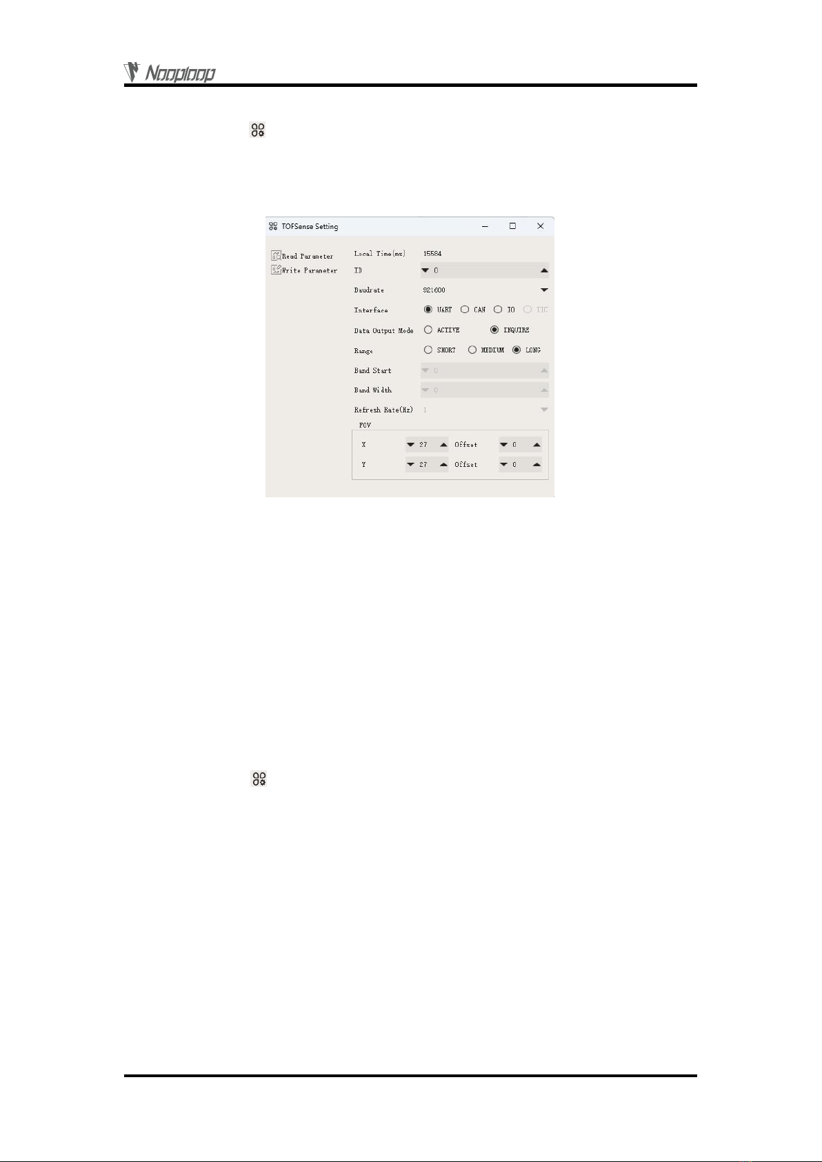
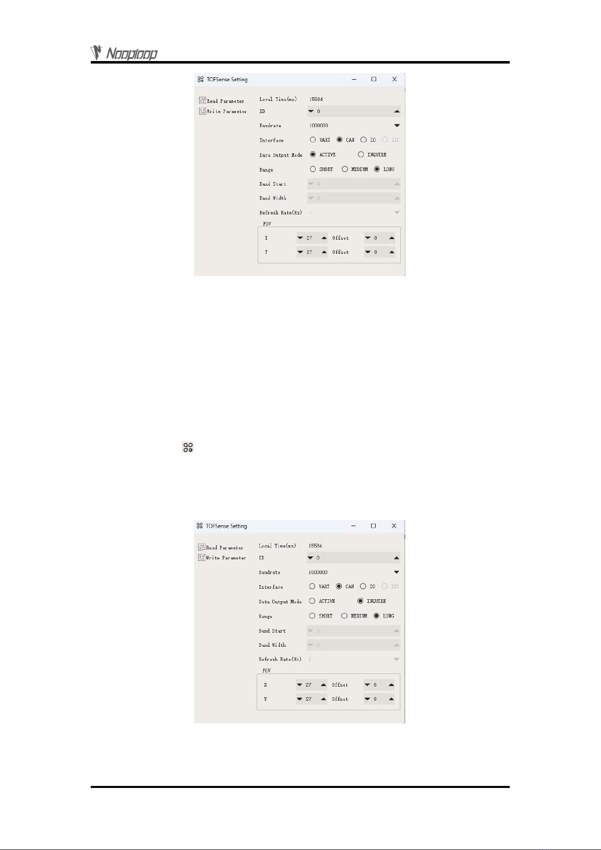
When the module is in UART mode (note that NAssistant cannot recognize modules in I/O mode),
TOFSense series products can be connected to the NAssistant software via a USB to TTL module
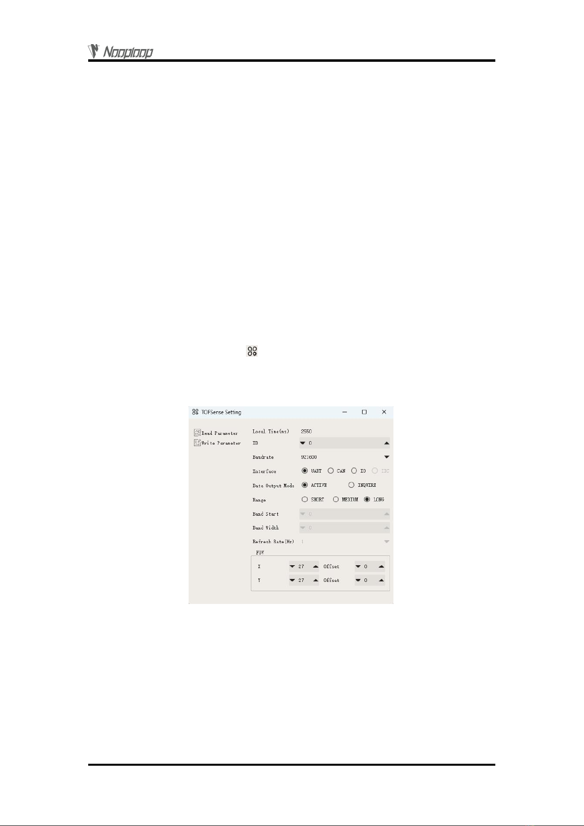
(referring to the data manual for wiring and power voltage). After successful identification, click to
enter the setting page . First, set the hysteresis starting point 'Band_Start' and the hysteresis width
'Bandwidth' to determine the hysteresis interval. The configuration diagram for I/O output mode is
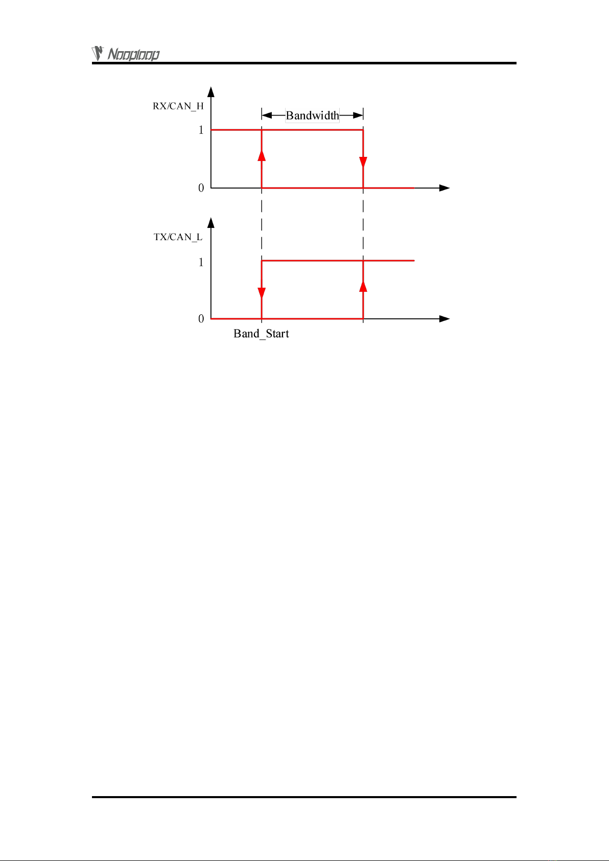
shown in Figure 5. The distance value is converted to a high or low level output by hysteresis
comparison, and the TX/CAN_L and RX/CAN_H outputs are complementary. The hysteresis
comparison schematic is shown in Figure 6. In this mode, the module cannot be cascaded. After
configuring the parameters, you need to click the 'Write Parameters' button to save the parameters.
Note: After switching to I/O mode, if you need to change parameters such as Band_Start and
Bandwidth, you can refer to the FAQ section to switch back to UART mode and then configure the
parameters.
For example, if Band_Start and Bandwidth are set to 500 (unit: mm), the low threshold value is
0.5 meters, and the high threshold value is 1 meter. When the ranging value is 0.3 meters, RX is high
level and TX is low level. When the ranging value increases to 0.8 meters, RX is high and TX is low.
When the ranging value exceeds 1 meter, the level is reversed, RX is low, and TX is high. When the
ranging value drops from more than 1 meter to 0.8 meters, RX is low and TX is high, and when the
ranging value drops below 0.5 meters, the level is reversed, RX is high, and TX is low.
If only one threshold value is needed, Bandwidth can be set to 0. Also note that the high level
output by the module is 3.3V, and the output current is small. When driving other devices, be sure to
check if it can be driven. If it cannot be directly driven, you can use a relay or other methods to drive it.
Figure 5: I/O output mode configuration diagram
The values of Band_Start and Bandwidth are in the range of [0~5000], with unit:mm.

NAssistant Operations
Copyright © Nooploop LTd 2023. All Rights Reserved.
9
Figure 6: Hysteresis comparison diagram
5NAssistant Operations
5.1 Firmware Update
Firmware upgrade requires a computer with internet access to install the NAssistant software. The
firmware is mainly divided into two types: public version firmware and test version firmware.
The steps for firmware update, reflash, and downgrade are as follows:
1.Click the firmware update button on the software's main page to enter the firmware update
page. It will automatically load the latest public version firmware (you can also click "Public Version
Firmware" to load the latest public version firmware after switching to other firmware). Click "Test
Version Firmware" and enter the firmware test code obtained from Nooploop's official website in the
pop-up window. Click "OK" to load the corresponding test version firmware.
2.Click the "Firmware Update" button to update the firmware (if the firmware version of the
module currently connected by NAssistant is lower than or equal to the loaded firmware version, then
the "Firmware Update" button will be grayed out and cannot be clicked. In this case, you need to click
the "Ignore Version" button first to downgrade or reflash with the same version).
3.Wait for the progress bar to reach 100 and the page to return to normal from grayed out.
Confirm whether the firmware version displayed on the main page is consistent with the loaded
firmware version. If it is consistent, it means the update was successful.

NAssistant Operations
Copyright © Nooploop LTd 2023. All Rights Reserved.
10
Figure 7: Firmware update page schematic diagram
5.2 Record, Replay and Export
NAssistant provides a convenient data recording, playback, and export function. Users can click
the button on the main page menu bar to start real-time raw data recording, and click the button
again to stop recording and output the *.dat file. The recorded *.dat file can be extracted by clicking the
button to open the default storage path and sent to the after-sales engineer for troubleshooting. The
software is equipped with a playback control bar, which can adjust the playback rate, progress, etc. (the
recorded data is the data received by the NAssistant software during the time between the two clicks of
the recording button).
Both real-time and playback modes can export text data to a local .xlsx file by clicking the button
. Click the button again to stop exporting and automatically open the folder where the file is located.
The exported data is the data received or played back by the NAssistant software during the time
between the two clicks of the export button.
Note: If the folder is not automatically opened, find the corresponding folder according to the log
prompt in the lower left corner of the software's main page, or click the menu button, click "Open Data
Folder", and look for it in the "export_data" folder.

FOV
Copyright © Nooploop LTd 2023. All Rights Reserved.
11
Figure 8: Data recording, playback, and export
6FOV
The field of view (FOV) parameter represents the angle that the module's emitted ranging light
can cover. The initial FOV parameter for the module is fov.x=27°, fov.y=27 °, fov.x_offset=0°,
fov.y_offset=0 °. By setting the X-direction FOV to 25 °, Y-direction FOV to 15 °, X-direction
offset to 1°, and Y-direction offset to -1°, the module's region of interest can be changed to the one
shown on the right side of Figure 9.
Figure 9: FOV configuration schematic diagram
A smaller FOV can improve the module's detection performance in narrow spaces and for small
objects. However, changes in the FOV angle can also affect the module's maximum ranging distance.
The smaller the FOV angle, the smaller the maximum ranging distance. The relationship between the
maximum ranging distance and the FOV angle for TOFSense in a certain scene (indoor, white wall
background) is shown in Figure 10. The measurements for TOFSense P and TOFSense PS are not yet

Cascade Ranging
Copyright © Nooploop LTd 2023. All Rights Reserved.
12
available. Users should choose the appropriate FOV angle based on their actual scene.
Figure 10 : The maximum ranging distance of TOFSense is related to the field of view (FOV)
7Cascade Ranging
Multiple sensors can be configured with different IDs and connected in series, and the ranging
information of all sensors can be read through a single communication interface. The connection
schematic is shown in Figure 11. TOFSense PS only has one communication interface, so a converter
is required for cascading.
Figure 11: Cascade ranging diagram
Under cascade ranging, three methods are suitable: UART query, CAN query, and CAN active
output.
8Protocol Unpack
8.1 Introduction
This chapter's protocol analysis examples are based on the NLink protocol, and you can also
download the NlinkUnpack sample analysis code developed in C language from the official website,
which can effectively reduce the user's development cycle.
Based on the data situation of TOFSense-F series products, in order to represent more data with
fewer bytes, we use integers to represent floating-point numbers and transmit them through protocol
frames. Therefore, when unpacking, the actual data with the multiplier is actually a floating-point
number and needs to be divided by the multiplier indicated in the protocol.
In particular, for int24 type, we need to first convert it to int32 type. To maintain the sign, we use
the method of left shift and then divide by 256. For example, for position data, we use int24 to
represent it, and the multiplier is 1000. The parsing code is as follows:
uint8_t byte[] = {0xe6,0x0e,0x00};//Decimal value: 3.814

Protocol Unpack
Copyright © Nooploop LTd 2023. All Rights Reserved.
13
//uint8_t byte[] = {0xec,0xfb,0xff};//Decimal value: -1.044
int32_t temp = (int32_t)(byte[0] << 8 | byte[1] << 16 | byte[2] << 24) / 256;
float result = temp/1000.0f;
Currently, the protocol verification is mainly based on the single-byte checksum at the end of the
protocol frame. Example code:
uint8_t verifyCheckSum(uint8_t *data, int32_t length){
uint8_t sum = 0;
for(int32_t i=0;i<length-1;++i){
sum += data[i];
}
return sum == data[length-1];
}
8.2 Example
The document assumes a single module continuous ranging scenario.
8.2.1 NLink_TOFSense_Frame0
Data source: Connect the module to the host computer, configure UART as active output mode,
using NLink_TOFSense_Frame0 protocol. For parsing distance data, please refer to the FAQ.
Raw data: 57 00 ff 00 9e 8f 00 00 ad 08 00 00 03 00 ff 3a
Table 1: NLink_TOFSense_Frame0 Parsing table
Data
Type
Length (Bytes)
Hex
Result
Frame Header
uint8
1
57
0x57
Function Mark
uint8
1
00
0x00
reserved
uint8
1
…
*
id
uint8
1
00
0
System_time
uint32
4
9e 8f 00 00
36766ms
dis*1000
uint24
3
ad 08 00
2.221m
dis_status
uint8
1
00
0
signal_strength
uint16
2
03 00
3
reserved
uint8
1
…
*
Sum Check
uint8
1
3a
0x3a
8.2.2 NLink_TOFSense_Read_Frame0
Data source: Connect the module to the host computer, configure it as UART query output mode
with ID set to 0. To query data, send the following bytes from the host computer. If you need to query
modules with different IDs, simply change the ID and checksum bytes accordingly.
Raw data: 57 10 FF FF 00 FF FF 63
Table 2: NLink_TOFSense_Read_Frame0 Parsing table
Data
Type
Length (Bytes)
Hex
Result
Frame Header
uint8
1
57
0x57
Function Mark
uint8
1
10
0x10

Protocol Unpack
Copyright © Nooploop LTd 2023. All Rights Reserved.
14
reserved
uint16
2
…
*
id
uint8
1
00
0
reserved
uint16
2
…
*
Sum Check
uint8
1
63
0x63
8.2.3 NLink_TOFSense_CAN_Frame0
Data source: Configure the module as CAN active output mode with ID set to 1, and connect it to
the CAN receiving device.
Raw data: StdID:0x201 + Data: AD 08 00 00 03 00 FF FF
Table 3: NLink_TOFSense_CAN_Frame0 Parsing table
Dominant level
Dominant or recessive level
Recessive level
8.2.4 NLink_TOFSense_CAN_Read_Frame0
Data source: The module is configured for CAN query output mode with an ID of 1. Connect the
CAN query device, and the query device's ID (id_s) is 2.
Raw data: StdID:0x402 + Data: FF FF FF 01 FF FF FF FF
Table 4: NLink_TOFSense_CAN_Read_Frame0 Parsing table
Field name
Part
Level
Type
Length(bits)
Hex
Result
Start Of Frame
SOF
*
1
*
*
Arbitration Field
ID
*
11
0x200+id
0x201
RTR
*
1
*
*
Control Field
IDE
*
1
*
*
r0
*
1
*
*
DLC
*
4
*
*
Data Field
dis*1000
uint24
24
ad 08 00
2.221m
dis_status
uint8
8
00
0
signal_strength
uint16
16
03 00
3
reserved
uint16
16
…
*
CRC Field
CRC
*
15
*
*
CRC_delimiter
*
1
*
*
ACK Field
ACK Slot
*
1
*
*
ACK_delimiter
*
1
*
*
End Of Frame
EOF
*
7
*
*
Field name
Part
Level
Type
Length(bits)
Hex
Result
Start Of Frame
SOF
*
1
*
*
Arbitration Field
ID
*
11
0x400+id_s
0x402
RTR
*
1
*
*
Control Field
IDE
*
1
*
*
r0
*
1
*
*

FAQ
Copyright © Nooploop LTd 2023. All Rights Reserved.
15
Dominant level
Dominant or recessive level
Recessive level
9FAQ
Q1. Can it be used outdoors (in bright light) conditions?
The module is affected by natural light. Generally speaking, the stronger the natural light, the
more it will be affected, resulting in shorter ranging distance, poorer accuracy, and larger fluctuations.
In strong light conditions (such as sunlight), it is generally recommended to use the module for
short-range detection scenarios.
Q2. Is there interference between multiple modules?
When multiple modules are working at the same time, even if the infrared light emitted from one
module crosses or hits the same position as another module, it will not affect the actual measurement.
However, if two modules are at the same horizontal height and facing each other, the measurement
may be affected for both of them.
Q3. Why is there no data output from TOFSense?
Each module has undergone strict testing before shipping. If there is no data, please first check if
the mode, wiring (power supply voltage, wire sequence correctness, and whether the pins on both sides
of the communication are conducting as recommended by using a multimeter to test), baud rate and
other configurations are correct. For CAN output mode, please check if the bus has termination
resistors (usually 120 Ω). For I/O output mode, please refer to the relevant section on I/O mode
introduction.
Q4. What should be noted during installation?
If you do not want to detect the ground or other reflective surfaces, it is necessary to avoid
obstructions within the FOV angle during installation. Additionally, the ground height should be taken
into consideration, and it is necessary to avoid obstructions such as ground reflections within the FOV.
If the installation height is close to the ground, the module can be slightly tilted upwards for
installation.
Q5. Are the module's UART, CAN, and I/O the same interface?
DLC
*
4
*
*
Data Field
reserved
uint24
24
…
*
id
uint8
8
01
id = 1
reserved
uint32
32
…
*
CRC Field
CRC
*
15
*
*
CRC_delimiter
*
1
*
*
ACK Field
ACK Slot
*
1
*
*
ACK_delimiter
*
1
*
*
End Of Frame
EOF
*
7
*
*

FAQ
Copyright © Nooploop LTd 2023. All Rights Reserved.
16
The UART interface and the CAN interface of the module share the same physical interface. To
switch between different communication modes, simply convert the corresponding wire sequence.
Please note that some models only support one communication mode.
Q6. After switching to CAN or IO mode, why can't the NAssistant software recognize the
module? How to switch between different communication modes?
Currently, the NAssistant software only supports the recognition of modules in UART mode. In
UART mode, after successful recognition by the host computer, the module can be configured as CAN
or IO communication mode on the settings page. In CAN or IO communication mode, hold down the
button and power on the module. When the indicator light changes from rapid flashing to slow flashing,
release the button. At this time, the module will forcibly enter temporary UART mode. Then, select the
UART mode on the settings page and write the parameters into the module through the host computer.
For TOFSense-PS, in CAN mode, you can use a USB-to-TTL module to connect to the host
computer. Change the baud rate to 921600 and connect it to the corresponding port of the USB-to-TTL
module. Click the recognition button several times to recognize the module normally.
Q7. What should be noted during firmware updates?
During the update process, do not power off or unplug the USB-to-TTL module. After clicking on
the firmware update, wait for the indicator light to change from fast flashing to slow flashing before the
module can be used normally.
Q8. Does the module output the shortest distance, the longest distance, or the average distance?
During a single measurement, the module will obtain multiple distance values within the FOV and
process them internally to output the distance with the highest proportion.
Q9. Does the module support outputting point cloud information?
The module can only output a single distance value at a time and does not currently support point
cloud information output.
Q10.How is distance output in different ranging modes, as well as when exceeding the range?
TOFSense:
In short-range mode, when the range is exceeded, the distance output is a fixed value of -0.01
(0xFFFFF6 in hexadecimal).
In medium-range mode, when the range is exceeded, the distance output jumps randomly between
1-2 meters. At this time, you can refer to the signal strength and distance status for judgment.
In long-range mode, when the range is exceeded, the data output jumps randomly between 1-2
meters. At this time, you can refer to the signal strength and distance status for judgment.
TOFSense P/TOFSense PS:
In all modes, when the ranging exceeds the measurement range, the data will jump. It is
recommended to judge the data availability directly through the distance status, and generally only a
distance status of 0 indicates that the data is available.
Q11.What is the reason for not being able to query data in CAN query mode?
First, make sure that the wire sequence between the CAN devices is correct. Secondly, the

Reference
Copyright © Nooploop LTd 2023. All Rights Reserved.
17
TOFSense series port does not contain a 120R matching resistor, so make sure that the resistance of the
query device matches. Finally, check whether the format of the sent query frame meets the
NLink_TOFSense_CAN_Read_Frame0 protocol, and pay special attention to the correct standard
frame ID.
Q12.What is the reason for not being able to enter UART configuration mode when holding
down the button?
The function button has been tested before shipment, if you cannot enter UART mode, please try
again several times. Please note that the button needs to be pressed before power on, and released after
the light flashes slowly.
Q13.What is the model of the serial communication terminal used by the module? What to do if
there is no such terminal interface on the flight controller or microcontroller?
The module uses GH1.25 terminals. You can purchase GH1.25 to other terminal adapter cables, or
cut the GH1.25-GH1.25 cable provided with the product and solder other terminals by yourself. For
wire sequence, power supply voltage, signal line voltage level, please refer to the data manual.
Q14.How to calculate the distance value from the received data "ad 08 00"?
The data in the protocol frame is stored in little-endian mode and is encoded by multiplying a
certain multiple. For example, if the hexadecimal data "ad 08 00" is restored, it becomes the decimal
value of 2221 after conversion to hexadecimal as 0x0008ad, and divided by 1000 to obtain the value of
2.221 meters.
Q15.How is the checksum calculated?
The checksum is calculated by adding up all the previous bytes and taking the lowest byte of the
result. For example, the checksum of "55 01 00 ef 03" is calculated as follows:
0x55+0x01+0x00+0xef+0x03=0x0148. The checksum is 0x48, so the complete data frame is "55 01 00
ef 03 48".
Q16.What should I do if there is an error during compilation or no data is obtained when using
the ROS driver package?
Before using the ROS driver package, users need to read the README.MD document in the
driver package, and follow the steps and precautions in the document to use it. Users can also refer to
the "ROS Driver Application Tutorial" on the official website for instructions on how to use it.
10 Reference
[1] TOFSense_Datasheet.pdf

Abbreviation and Acronyms
Copyright © Nooploop LTd 2023. All Rights Reserved.
18
11 Abbreviation and Acronyms
Table 5: Abbreviation and Acronyms
Abbreviation
Full Title
TOF
Time of Flight
FOV
Field of View
HW
Half Wave
VCSEL
Vertical Cavity Surface Emitting Laser
12 Update Log
Table 6: Update Log
Version
Firmware Version
Data
Description
1.0
1.0.0
20190817
1. Publish the initial version of the manual.
1.1
1.0.4
20190923
1. Add examples for FOV settings through UART
2. Add FOV setting instructions
3. Add FAQ
4. Fix errors in the manual
1.2
1.0.6
20191213
1. Add instructions for FOV settings
2. Fix errors in the manual
2.0
2.0.0
20200730
1. Add I/O mode instructions
2. Expand FAQ
3. Fix errors in the manual
2.1
2.0.0
20210623
1. Add descriptions for TOFSense P and TOFSense PS
2. Expand FAQ
3. Optimize manual descriptions
2.2
2.0.3
20220211
1. Optimize manual descriptions
2.3
2.0.4
20220924
1. Add certification-related instructions
2.4
2.0.4
20221205
1. Optimize manual descriptions
2.5
2.0.4
20230404
1. Add firmware update descriptions
2. Expand FAQ and optimize some descriptions
13 Further Information
Company: SZ Nooploop Technology Co.,Ltd.
Address: A2-207, Peihong building, No. 1, Kehui Road, Science Park community, Yuehai street,
Nanshan District, Shenzhen
E-amil: marketing@nooploop.com
Website: www.nooploop.com
Table of contents
Other Nooploop Accessories manuals