EIM Lab-OnThe-Go User manual

Table of Contents
01 - Learn Electronics with Confidence ...................................................
02 - Setting Up a Miniature Electronics Lab .............................................
Breadboard ................................................................................
Power Supply .............................................................................
Multimeter .................................................................................
Oscilloscope ..............................................................................
Function Generator ....................................................................
03 - Prepare Componets and Tools .........................................................
Wires ..........................................................................................
Resistors .....................................................................................
Capacitors ..................................................................................
Operational Amplifier ................................................................
Diodes ........................................................................................
Bipolar Junction Transistor ........................................................
555 Timer ...................................................................................
04 - Get Started with Circuits ..................................................................
4.1 - Simple LED Circuit .............................................................
4.2 - Touch Sensor ......................................................................
4.3 - Half Wave Rectifier .............................................................
4.4 - Astable Multivibrator Circuit ...............................................
4.5 - Soil Moisture Detector ........................................................
4.6 - Flashing LED with 555 Timer ..............................................
4.7 - A Lousy Hypnotizer ............................................................
4.8 - Breathing LED ....................................................................
4.9 - Inverting Amplifier ..............................................................
4.10 - Non-inverting Amplifier ....................................................
Apx A - User Guidance of the Power Supply (MEGO) ..............................
Apx B - User Guidance of the Multimeter (VEGO) ...................................
Apx C - Integrated Signal Generator and Oscilloscope (Zoolark) ............
Apx D - Commonly Used Electrical Symbols ...........................................
1
3
3
5
7
8
10
13
13
14
16
18
19
20
22
25
25
26
28
29
31
33
35
37
38
40
41
45
49
57
i

ii
Learn Electronics with Condifence
Learning electronics, circuits and hardware can be a fascinating journey,
but it always comes with its own set of challenges:
• Abstract concepts that may be difficult to understand
• Heavy equations and calculations are required to learn the subject
• Limited access to equipment that is necessary for hands-on learning
• Safety concerns that may cause injury or damage to equipment
• Almost impossible to self-practice outside of a professional lab
Today we are living in a world of abundance. Our young generations
should have the opportunity to explore electronics and develop their
creativity and problem-solving skills, without being held back by financial
barriers of accessing necessary equipment or outdated teaching methods
that lack hands-on experiences.
CH 1
1
1. Learn Electronics with Condifence
Lab-On-The-Go ManualLOTG
2
Studies have shown that the learning and cognition processes are most
effective when your eyes, hands and brain are actively engaged. With
Lab-On-The-Go, learning electronics is no longer restricted on theories
in books or pure simulations on a screen, more importantly, you own the
opportunity to hands-on tryout real components and establish deeper
comprehensions during the building and testing process.
We hope this Lab-On-The-Go kit unlocks your passion of electronics and
become your best companion on the journey of learning electronics. Do
not just learn from the book, learn from the mistakes!
As a leading supplier in Educational Technology, we are committed to
offering solutions that help to address those issues existed in electronics
learning and teaching. The hardware kit you just opened is called Lab-On-
The-Go, a set of portable and handy equipment and tools that allows you
gain hands-on practices while learning the concepts of electronics and
circuits.

Setting Up a Miniature Electronics Lab CH 2
3
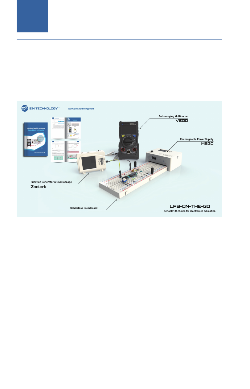
The Lab-On-The-Go (or LOTG) learning kit includes a complete set of
portable and handy equipment that allows you learn, build and test many
fancy circuits with minimum setting up efforts and dependencies. Once
first open the package, you should observe 4 tools:
If you have no prior knowledge of using these tools, please take a moment
to read the simple starter guidance before jumping ahead.
A breadboard is a reusable prototyping tool allows you to build and test
electronic circuits without the need for soldering. It consists of a plastic
board with numerous holes drilled into it. The holes are arranged in a
grid pattern, and are used to insert components and wires. A full-sized
breadboard has 820 holes whereas a half-sized breadboard has 410 holes.
In LOTG hardware, you will find a half-sized breadboard.
2. Setting Up a Miniature Electronics Lab
Breadboard
Lab-On-The-Go ManualLOTG
4
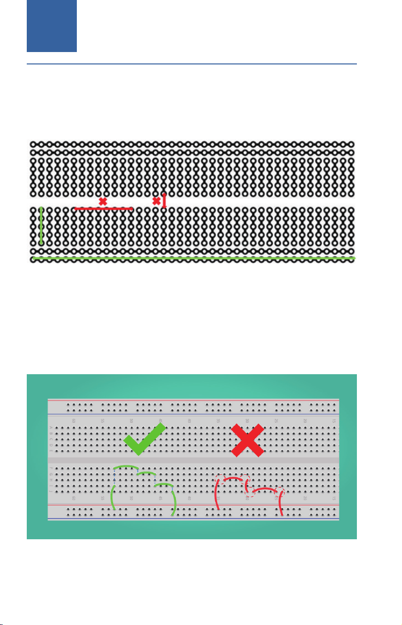
An X-ray diagram of the breadboard internal holes is illustrated below.
Holes with interconnected wires indicate they are electrically conductive.
Typically, the 4 rows serve as power rails and 30 columns are reserved for
wiring components.
In electronics, a functional circuit should have a closed loop for the path of
electrical current. While building circuits on a breadboard, it is important
to plan ahead and carefully consider the placement of each component.
The figure below shows some common mistake for first time breadboard
users. More breadboard circuiting examples and tricks will be found in
later sections of this tutorial.

Setting Up a Miniature Electronics Lab CH 2
5
A DC power supply is an essential tool in any electronics laboratory. It
provides a stable and adjustable source of DC voltage, which is necessary
to feed electrical power to the rest of elements in a circuit. The power
supply included in the LOTG hardware kit is called MEGO, which is a
rechargeable breadboard compatible power supply with features to adjust
and display output voltage.
Power Supply

Lab-On-The-Go ManualLOTG
6
The MEGO power supply can directly plug-fit to the breadboard power
rails without using extra wires or power outlets. As shown in the figure
below, when MEGO is plugged on one side of the breadboard, the two
power rails have the same voltage as displayed on the power supply.
Make sure the polarity markings on breadboard match to the “+” and “-“
markings on the power supply.
The two power ports on each side of MEGO were internally shorted, which
means the power rails of breadboard can only have a single voltage. If
such a setting is not desired, you may access the voltage from USB output
port using the alligator clips.
The MEGO power supply is rated for 5W which is designed for low power
circuits built on a breadboard. For power thirsty applications you need
to use a benchtop power supply or our Pro-series design (expected to
release in early 2024).
More detailed user manual and technical specifications of MEGO can be
found in Appendix A.
Do not use this USB port to charge your phones or tablets since it
may generate other than 5V output voltages.

Setting Up a Miniature Electronics Lab CH 2
7
A multimeter is another important tool commonly seen in most
electronics labs. A digital multimeter, also known as DMM, is capable to
measure various electrical properties such as voltage, current, resistance
and conductivity, which are key parameters while diagnosing and
troubleshooting electrical circuits.
The compact DMM included in the LOTG kit which is named VEGO. It
requires two AAA batteries to operate. Before you start, open the lid from
back and mount two batteries. VEGO is very power efficient which usually
gives over 1 year of battery life.
On technical side, VEGO is a versatile and user-friendly multimeter ideal
for electronics experiments and projects. It has auto-ranging feature
that automatically adjusts to display the most appropriate range for the
quantity being measured. VEGO can also measure capacitance and
temperature making them useful in more advanced applications.
Multimeter

Lab-On-The-Go ManualLOTG
8
For experimental purposes, you will also find the accessory alligator clips
being particularly handy. By attaching to the wires being measured, your
hands can be freed for other work. The VEGO multimeter has a feature
that automatically switches off the device if it is not used for 5 minutes.
This helps to extend the battery life of the device and ensures that the
battery is not drained unnecessarily.
More detailed technical specifications can be found in Appendix B.
An oscilloscope is a sophisticated instrument used to measure, analyze,
and display electrical signals. It provides a visual representation of
electrical waveforms in real-time, making it an essential tool in electronics
labs. Most modern oscilloscopes you have seen are like the one shown
below, with advanced features and capabilities such as high bandwidths,
fast sampling rates, multiple channels and memory space. However, these
advanced oscilloscopes can be prohibitively expensive, typically costing
four figures, making them unaffordable for schools and individuals.
Oscilloscope

Setting Up a Miniature Electronics Lab CH 2
9
The oscilloscope you will find in the kit is called Zoolark, which is a
miniature device that has multiple functions integrated into it. Zoolark is
significantly less expensive than industrial oscilloscopes yet it still allows
you to perform basic waveform scoping and measurements.
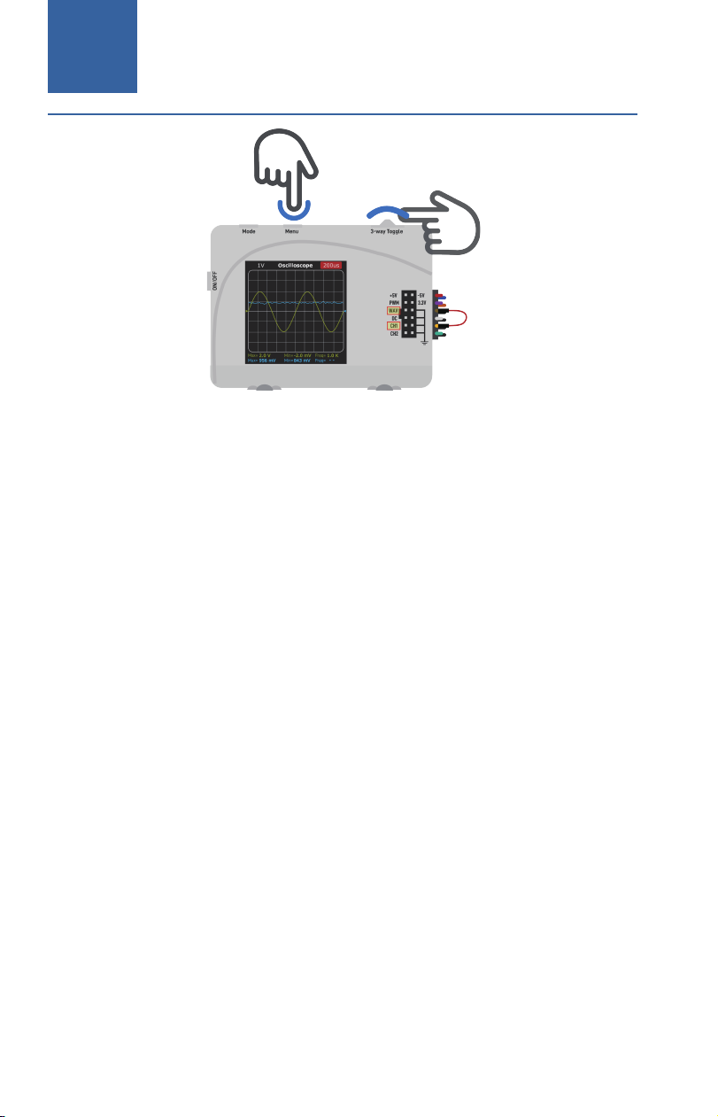
To use Zoolark as an oscilloscope, you need to set it to waveform scoping
mode. Use Channel 1 (CH1) and/or CH2 to probe the signal to be
measured. All four ground pins on Zoolark are internally shorted so you
can use them interchangeably.
While measuring the signal, you need to adjust the time/div and voltage/
div to appropriate scale. If the signal being measured is a periodic AC
signal, we recommend to set the time such that 2-3 complete cycles can
be displayed in the screen. For example, if you use a wire to short WAV
and CH1 as indicated, you should observe a sine wave on the screen.
Adjust the time setting until only 2 cycles are displayed in the screen, and
you should see the measurements are getting more stable.
Lab-On-The-Go ManualLOTG
10
The Zoolark oscilloscope is designed to assist novice users in gaining
a qualitative understanding of waveform properties and serves as a
convenient tool for troubleshooting and circuit testing. You will still
need to rely on industrial level benchtop oscilloscopes for more precise
quantitative measurement results. When you find Zoolark is being less
capable for your needs, congratulations, since it indicates you are reaching
a higher level of skills and being more prepared for next stage of academic
and career development.
Please refer to Appendix C for more detailed technical information
regarding to Zoolark.
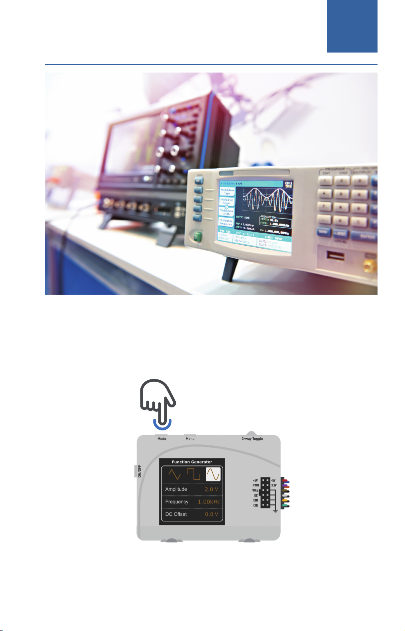
One more important instrument you are expected to see in most
electronics labs is a function generator, which is used to generate various
types of waveforms, such as sine, square, and triangular signals over a
wide range of frequencies. Function generators are primarily used in
the test and debugging of analog circuits for which they serve as a well-
controlled signal excitation source to test the response of the system. A
benchtop function generator example is shown below.
Function Generator
Setting Up a Miniature Electronics Lab CH 2
11
Do not get frustrated if you do not immediately see a function generator
in the LOTG kit. In fact, the function generation feature is integrated in the
same Zoolark device. To turn on the function generator on Zoolark, switch
to the signal generation interface using the Mode selection button.

Lab-On-The-Go ManualLOTG
12
Zoolark function generator is able to synthesize three types of AC signals:
triangular, square and sinusoidal. You can also adjust the amplitude,
frequency and DC offset (vertical shift) using the buttons. The generated
signal can be accessed using the WAV pin at the debugging port.
A high-end function generator designed for use on a workbench may
come with extra features that allow it to produce higher frequency,
modulated signals, frequency sweeps or data bursts, which will inevitably
result in a significantly higher price tag.

Prepare Components and Tools CH 3
13
3. Prepare Components and Tools
In an electrical circuit, all devices and components are interconnected by
wires. Wires are made of metal that is covered by a protective layer for
insolation purposes. The internal core metal of wires is typically made of
copper or aluminum. Some key properties between the two materials are
compared in the Table below. In general, copper wires are more used due
to better conductivity and anti-corrosion.
Jumper wires are often used in circuiting experiments. They are short
pieces of single core wire with bare metal leads at two terminals so that we
can easily connect on breadboards or other components.
Wires
Property Copper Aluminum
Electrical conductivity Excellent Good
Durability Excellent Good
Corrosion resistance Excellent Good
Recyclability Excellent Good
Weight Heavy Light
Cost High Low

Lab-On-The-Go ManualLOTG
14
You should note that main purpose of jumper wires is to setup electrical
connections between components, but are not designed to load high
current. For circumstances which you need to load current higher than 1A,
it is recommended to use wires of higher current ratings.
If you want your circuit looks neater, the single core breadboard hookup
wires are good alternatives. These wires come in various lengths and
thicknesses, and can be easily inserted into the holes on a breadboard to
create electrical connections between components.
Resistors are a very important component in electric circuit that can
resist or regulate the current flow in a circuit. Electrically, resistors are
a two terminal device measured in terms of resistance, with the unit of
measurement being the Ohms (Ω). Other commonly used resistance units
include kΩ and MΩ. Resistors can also be classified into various types
based on the fabrication technologies or the purposes of usage.
Resistors
Prepare Components and Tools CH 3
15
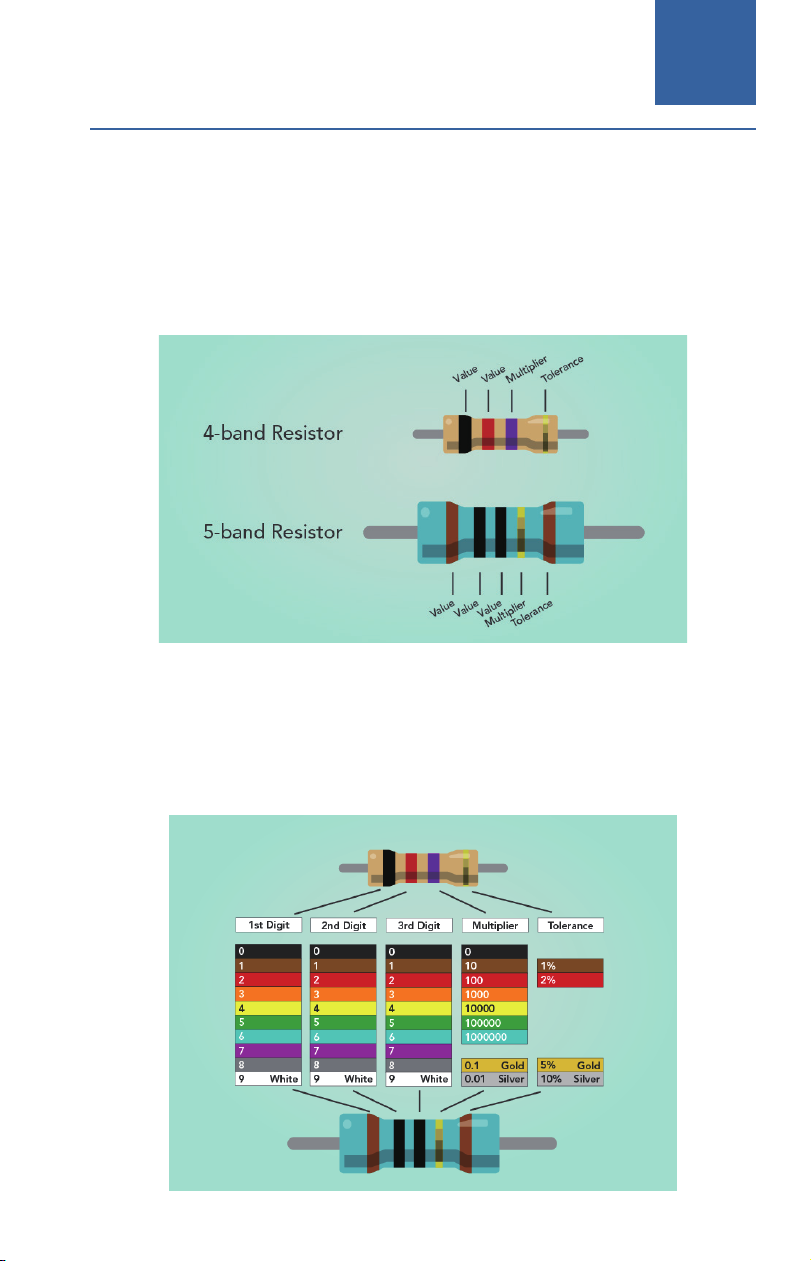
The commonly used resistors in breadboard circuiting are carbon film
resistors and metal film resistors. Manufacturers use a color code system
that consists of bands of color painted on the resistor and make it easier to
identify the resistor value. There are typically four bands or five bands on a
resistor, and each band represents a specific digit in the resistance value as
labeled in the illustration.
For 4-band or 5-band resistors, each band represents a specific digit in
the resistance value. For color banded resistors, the first two or three color
bands represent the significant digits, and the last band represents the
multiplier, which indicates the number of zeros to add to the significant
digits.
Lab-On-The-Go ManualLOTG
16
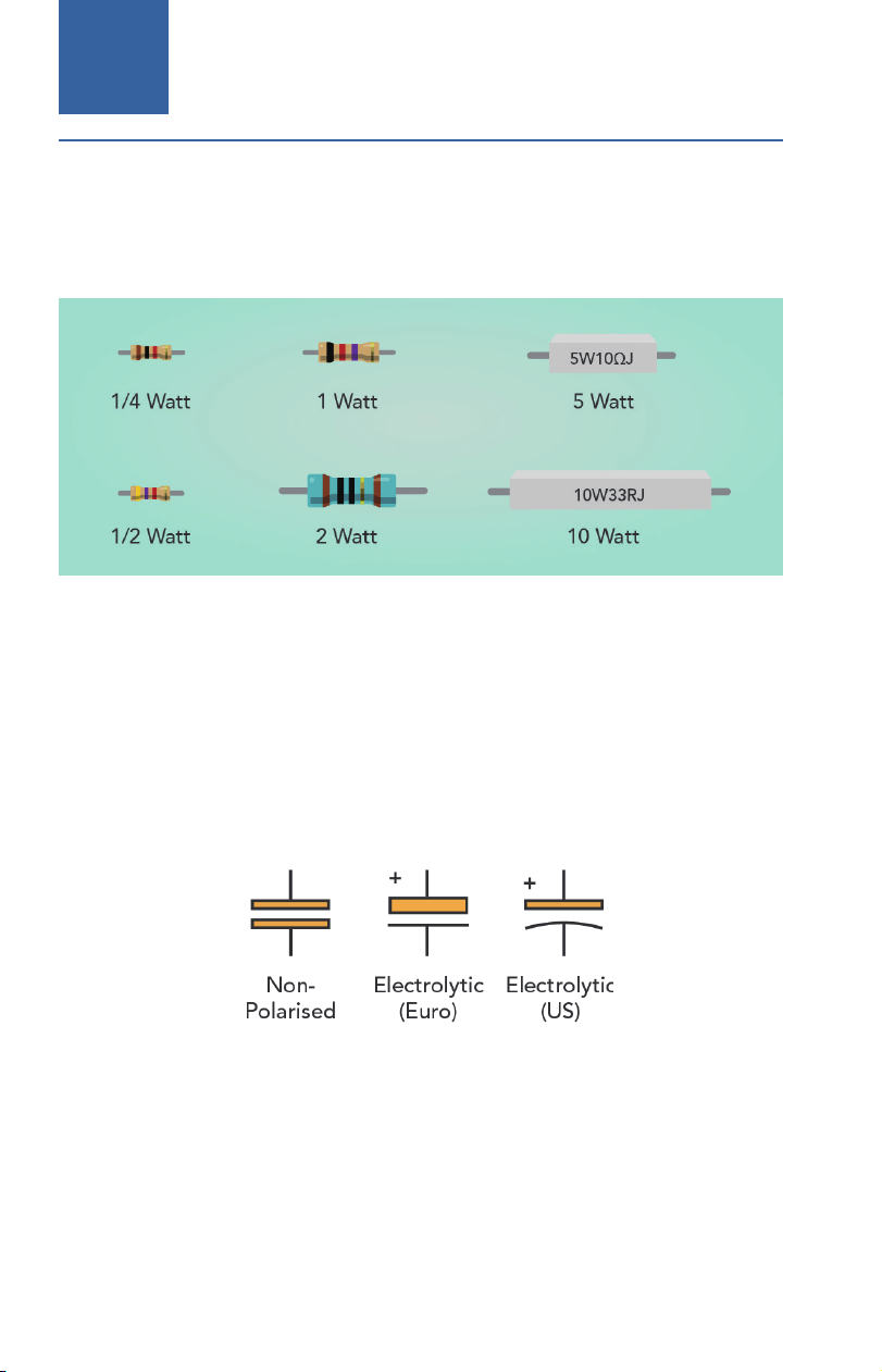
The resistors included in the kit bag have nominal power of 1/4W, which
is not designed to load big current. For applications that larger current is
flowing through the resistor (meaning a higher voltage is applied across
the two terminals), you need use bigger resistors with higher rated power.
A capacitor is a two terminal circuit element which consists of two
conducting surfaces separated by a non-conducting dielectric material.
The capacitor value, or capacitance, is measured in units of farads (F). In
electronics, the units of microfarads (uF), nanofarads (nF) and picofarads
(pF) are more often used. There are three commonly used electrical
symbols for capacitors as shown below.
Capacitors
Prepare Components and Tools CH 3
17
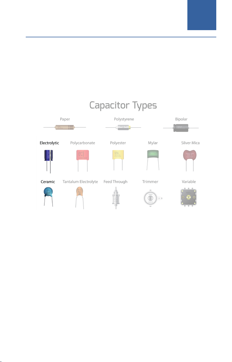
The fabrication process of capacitors may vary to serve for different
engineering purposes.
For general circuiting purposes, ceramic and electrolytic type capacitors
are more often used. Electrolytic capacitors are polarized so we will always
connect the negative polarity to lower voltage.
Being a very important component, the key characteristics of a capacitor
is that it can block DC current while still allowing AC current to pass.
This property makes capacitors a very favored component in functions
such as filtering, smoothing and timing. We have included some exercise
circuits in this guide but you are encouraged to investigate more in-depth
knowledge in our book named Laboratory Manual to Accompany Basic
Electric Circuits.
Lab-On-The-Go ManualLOTG
18
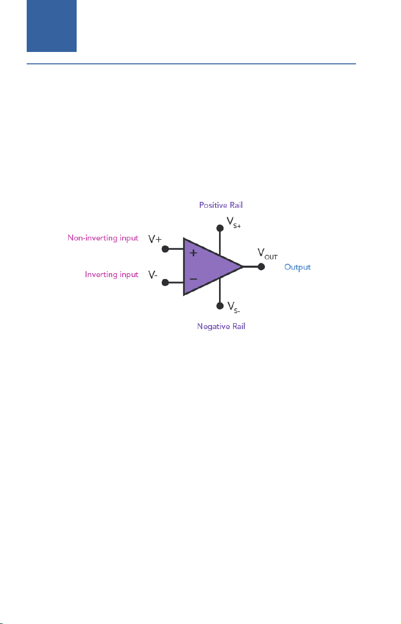
The operational amplifier (Op-amp) was first invented by Karl D. Swartzel
Jr. in 1941 and was initially used in analog computers (and soon being
used as artillery director during WWII). It has since become a ubiquitous
component in electronic circuits, used for amplification, filtering, and
signal conditioning. Symbolically, an Opamp has two signal inputs, a pair
of power rails and an output port.
Op-amps have high gain, high input impedance, low output impedance,
and are designed to have a very stable gain over a wide range of
frequencies. They are typically implemented as integrated circuits (ICs)
and come in various packages. The Opamp included in the kit is LM358,
which has a black rectangular case with 8 pins distributed in two parallel
rows. This package is called Dual Inline package, or DIP 8 since it contains
8 pins, that can be easily plug-fit onto a breadboard.
Operational Amplier
Table of contents
Popular Educational Equipment manuals by other brands

Aircatglobal
Aircatglobal VirtualFly SWITCHO TRIMS user manual

Nasco Healthcare
Nasco Healthcare Life/form LF03608 instruction manual

Limbs & Things
Limbs & Things 60000 user guide

CES
CES Ed-Lab 7000 Experiment manual

RoboMaster
RoboMaster S1 Education Expansion Set Core quick start guide

Rocket
Rocket R150+ instructions

DVDO
DVDO DVDO-RS-2 user manual

Reality Works
Reality Works Muscular Figure Natural Size quick start guide

Nasco Healthcare
Nasco Healthcare DANi LF04500 instruction manual

Prestan
Prestan Professional AED Trainer PLUS 4-Pack manual

pitsco
pitsco LUMA user guide

H-TEC Education
H-TEC Education F107-PEMFC Kit operating instructions


