EINHELL AT 1 User manual

Montageanleitung
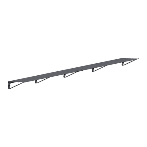
Universal Ablagetisch
Assembly Instructions
Universal table
Instructions de montage
Table unverselle
Istruzioni per il montaggio
Tavolo die appoggio universale
Monteringsanvisningar
Universalbord
Montážní návod
Univerzální odkládací stůl
Návod na montáž
Univerzálny odkladaci stôl
Art.-Nr.: 36.004.60 I.-Nr.: 01016 AT
1
Montageanleitung AT 1 SPK7 26.04.2006 8:42 Uhr Seite 1

1
2
2
7
3
2
4
1
Montageanleitung AT 1 SPK7 26.04.2006 8:42 Uhr Seite 2

3
3 4
5 6
7
3
3
Montageanleitung AT 1 SPK7 26.04.2006 8:42 Uhr Seite 3

4
1. Empfehlungen:
Zur Vermeidung von Unfällen sollten sich während
der Montage keine Kinder in unmittelbarer Nähe
befinden
2. Wichtige Sicherheitshinweise
Bei der Montage der Alu-Profile – scharfe Kanten
– Schutzhandschuhe tragen.
Bei der Montage der Alu-Profile – Quetschgefahr
– Schutzhandschuhe tragen.
Nach ca. 2 Wochen alle Schraubverbindungen
nachziehen! Danach alle 3 Monate die Schraub-
verbindungen überprüfen und gegebenenfalls
nachziehen.
3. Teilebeschreibung (s. Abb. 1)
Pos. Bezeichnung Stückzahl
01 Winkelprofil 800 mm 8
02 Winkelprofil 615 mm 4
03 Diagonalstrebe 150 mm 8
04 Ablageblech 6
05 Sechskantschraube M6x10 40
06 Sechskantmutter M6 40
07 Verbindungsstück 50 mm 4
Abmessungen (L x T x H) ca. 800 x 615 x 800 mm
Sollten Sie mehr Abstellfläche benötigen, so können
Sie den Tisch verlängern, indem Sie an das
Verbindungsstück (7) einen weiteren Tisch
anschrauben.
4. Montagehinweise
Zur Montage benötigen Sie einen Gabelschlüssel
SW 10 mm.
Ziehen Sie die Schrauben erst am Montageende
fest an.
Beachten Sie bei allen Montageschritten die Abb.
1 und die im nachfolgenden Montagetext ange-
gebenen Abbildungen.
5. Montage
1. Montieren Sie zuerst den unteren und oberen
Rahmen (Abb. 2).
Achten Sie unbedingt darauf, die Schraubenköpfe
auf der Innenseite liegen (Abb. 3).
2. Schrauben Sie die Standfüße an den oberen
Rahmen. Beachten Sie, dass die Verbindungs-
stücke (7) an einer Längsseite mit verschraubt
werden müssen (Abb. 4).
Achten Sie unbedingt darauf, dass auf der kurzen
Seite des Rahmens die Schraubenköpfe auf der
Innenseite liegen (Abb. 5).
3. Schrauben Sie die Diagonalstreben (3) an (Abb.
6). Achten Sie unbedingt darauf, dass auf der
kurzen Seite des Rahmens die Schraubenköpfe
auf der Innenseite liegen.
4. Schrauben Sie den unteren Rahmen an die
Standfüße. Beachten Sie, dass die Verbindungs-
stücke (7) an der gleichen Längsseite wie am
oberen Rahmen verschraubt werden müssen.
5. Nachdem Sie den verschraubten Rahmen
waagerecht ausgerichtet haben, können Sie die
Schrauben festziehen.
6. Legen Sie die Ablagebleche auf den oberen
Rahmen.
6. Ersatzteilbestellung
Bei der Ersatzteilbestellung sollten folgende
Angaben gemacht werden:
Typ des Gerätes
Artikelnummer des Gerätes
Ident-Nummer des Gerätes
Ersatzteil-Nummer des erforderlichen Ersatzteils
Aktuelle Preise und Infos finden Sie unter
www.isc-gmbh.info
D
Montageanleitung AT 1 SPK7 26.04.2006 8:42 Uhr Seite 4

5
1. Recommendations:
To prevent accidents it is best to make sure that
there are no small children in the direct vicinity during
the assembly work.
2. Important safety instructions
Wear safety gloves when assembling the
aluminium profiles – sharp edges!
Wear safety gloves when assembling the
aluminium profiles – risk of crushing!
Retighten all the screw connections after
about 2 weeks. Thereafter check the screw
connections every 3 months and retighten if
necessary.
3. Description of parts (see Fig. 1)
Item Description Quantity
01 Angle section, 800 mm 8
02 Angle section, 615 mm 4
03 Diagonal strut, 150 mm 8
04 Metal shelf 6
05 Hex screw M6 x 10 40
06 Hex nut M6 40
07 Connecting piece, 50 mm 4
The dimensions (L x D x H) are approx. 800 x 615 x
800 mm.
If you should require more storage space you can
extend the table by screwing another table to the
connecting piece (7).
4. Installation notes:
To assemble, you will require a SW 10 mm open-
ended wrench.
Tighten the screws at the installation end first.
Refer to Fig. 1 and the illustrations in the following
installation text for each step you take to
assemble and install.
5. Assembly
1. First assemble the upper and lower frames (Fig.
2). It is imperative that you make sure that the
screw heads are on the inside (Fig. 3).
2. Screw the legs to the upper frame. Make sure that
the connecting pieces (7) are screwed onto one of
the longitudinal sides at the same time (Fig. 4).
It is imperative that you make sure that the screw
heads are on the inside on the short side of the
frame (Fig. 5).
3. Screw on the diagonal strut (3) (Fig. 6). It is
imperative that you make sure that the screw
heads are on the inside on the short side of the
frame.
4. Screw the lower frame to the legs. Make sure that
the connecting pieces (7) are screwed onto the
same longitudinal side as on the upper frame.
5. Align the frame horizontally once it has been
screwed together and then tighten the screws.
6. Place the metal shelves on the upper frame.
Ordering replacement parts
Please quote the following data when ordering
replacement parts:
Type of machine
Article number of the machine
Identification number of the machine
Replacement part number of the part required
For our latest prices and information please go to
www.isc-gmbh.info
GB
Montageanleitung AT 1 SPK7 26.04.2006 8:42 Uhr Seite 5

6
1. Recommandations :
Pour éviter des accidents, évitez que des enfants
soient à proximité immédiate pendant le montage
2. Consignes de sécurité importantes
Lors du montage des profilés en aluminium -
arêtes acérées- portez des gants de protection.
Lors du montage des profilés en aluminium -
risque d’écrasement- portez des gants de
protection.
Après env. 2 semaines, resserrer tous les
raccords vissés ! Contrôlez ensuite les raccords
vissés une fois tous les trimestres et les resserrer
le cas échéant.
3. Description des pièces (voir fig. 1)
Rep. Désignation Nombre de pièces
01 Profil angulaire 800 mm 8
02 Profil angulaire 615 mm 4
03 Barre diagonale 150 mm 8
04 Tôle de dépose 6
05 Boulon hexagonal M6x10 40
06 Ecrou hexagonal M6 40
07 Pièce de raccordement 50 mm 4
Dimensions (L x pr x H) env. 800 x 615 x 800 mm
Si vous avez besoin de plus de surfaces de dépose,
il est possible de rallonger la table en vissant une
autre table à la pièce de raccordement.
4. Consignes de montage
Pour le montage, vous aurez besoin d’une clé à
fourche de 10 mm d’ouverture.
Resserrez à fond les vis uniquement à la fin du
montage.
Reportez-vous pour toutes les étapes du montage
à la fig. 1 et aux illustrations suivantes qui se
trouvent dans le texte montage.
5. Montage
1. Montez tout d’abord les châssis inférieur et
supérieur (fig. 2). Veillez absolument à ce que les t
êtes des vis se trouvent bien à l’intérieur (fig. 3).
2. Vissez les pieds au châssis supérieur. Veillez à ce
que les pièces de raccordement (7) soit bien
vissées sur un côté longitudinal (fig. 4). Veiller
absolument à ce que les têtes de vis se trouvent
bien à l’intérieur côté court du châssis (fig. 5).
3. Vissez les barres diagonales (3) (fig. 6). Veiller
absolument à ce que les têtes de vis se trouvent
bien à l’intérieur côté court du châssis.
4. Vissez le châssis inférieur aux pieds. Veillez à ce
que les pièces de raccordement (7) soient vissées
sur le même côté longitudinal que sur le châssis
supérieur.
5. Une fois le châssis vissé aligné à l’horizontale, on
peut resserrer les vis à fond.
6. Placez la tôle de dépose sur le châssis inférieur
Commande de pièces de rechange
Pour les commandes de pièces de rechange,
veuillez indiquer les références suivantes:
Type de l’appareil
No. d’article de l’appareil
No. d’identification de l’appareil
No. de pièce de rechange de la pièce requise
Vous trouverez les prix et informations actuelles à
l’adresse www.isc-gmbh.info
F
Montageanleitung AT 1 SPK7 26.04.2006 8:42 Uhr Seite 6

7
1. Suggerimenti :
Per evitare degli incidenti durante il montaggio non ci
devono essere bambini nelle immediate vicinanze
2. Importanti avvertenze di sicurezza
Durante il montaggio dei profili in alluminio -
spigoli appuntiti - mettetevi guanti protettivi.
Durante il montaggio dei profili in alluminio -
pericolo di schiacciamento - mettetevi guanti
protettivi.
Dopo ca. 2 settimane serrate di nuovo tutti i
collegamenti a vite! Poi controllate i collegamenti
a vite una volta ogni tre mesi e serrateli di nuovo
se necessario.
3. Descrizione delle parti (vedi Fig. 1).
Pos. Denominazione Quantità
01 Profilato angolare 800 mm 8
02 Profilato angolare 615 mm 4
03 Barra diagonale 150 mm 8
04 Lamiera di appoggio 6
05 Vite a testa esagonale M6x10 40
06 Dado a testa esagonale M6 40
07 Raccordo 50 mm 4
Dimensioni (l x p x a) ca. 800 x 615 x 800 mm
Se avete bisogno di una superficie di appoggio
maggiore potete allungare il tavolo avvitando un altro
tavolo al raccordo (7).
4. Avvertenze di montaggio
Per il montaggio avete bisogno di una chiave fissa
n. 10 mm.
Avvitate bene le viti quando avete terminati i lavori
di montaggio.
In tutte le fasi di montaggio osservate la Fig. 1 e le
figure riportate nel seguente testo di montaggio.
5. Montaggio
1. Montate prima il telaio inferiore e superiore (Fig.
2). Fate assolutamente attenzione che le teste
delle viti si trovino sul lato interno (Fig. 3).
2. Avvitate le gambe sul telaio superiore. Tenete
presente che i raccordi (7) devono essere avvitati
su un lato lungo (Fig. 4).Fate assolutamente
attenzione che, sul lato corto del telaio, le teste
delle viti si trovino sul lato interno (Fig. 5).
3. Avvitate le barre diagonali (3) (Fig. 6). Fate
assolutamente attenzione che, sul lato corto del
telaio, le teste delle viti si trovino sul lato interno.
4. Avvitate il telaio inferiore alle gambe. Tenete
presente che i raccordi (7) devono essere avvitati
sullo stesso lato lungo del telaio superiore.
5. Dopo avere orientato il telaio avvitato in posizione
orizzontale potete serrare le viti.
6. Mettete le lamiere di appoggio sul telaio superiore.
Commissione dei pezzi di ricambio
Volendo commissionare dei pezzi di ricambio, si
dovrebbe dichiarare quanto segue:
modello dell’apparecchio
numero dell’articolo dell’apparecchio
numero d’ident. dell’apparecchio
numero del pezzo di ricambio del ricambio
necessitato.
Per i prezzi e le informazioni attuali si veda
www.isc-gmbh.info
I
Montageanleitung AT 1 SPK7 26.04.2006 8:42 Uhr Seite 7

8
1. Rekommendation :
För att undvika olyckor bör inga barn befinna sig i
närheten medan hyllan monteras.
2. Viktiga säkerhetsanvisningar
Bär skyddshandskar när du monterar samman
aluminiumprofilerna - vassa kanter.
Bär skyddshandskar när du monterar samman
aluminiumprofilerna - risk för klämskador.
Dra åt alla förskruvningar efter ca 2 veckor!
Kontrollera sedan förskruvningarna en gång i
kvartalet och dra åt vid behov.
3. Beskrivning av delarna (se bild 1)
Pos. Beteckning Antal
01 Vinkelprofil 800 mm 8
02 Vinkelprofil 615 mm 4
03 Diagonalstöd 150 mm 8
04 Avläggningsplåt 6
05 Sexkantskruv M6x10 40
06 Sexkantmutter M6 40
07 Kopplingsdel 50 mm 4
Mått (L x D x H) ca 800 x 615 x 800 mm
Om du behöver mer avläggningsyta kan du förlänga
bordet genom att skruva fast ytterligare ett bord vid
kopplingsdelen (7).
4. Monteringsanvisningar
Till monteringen behövs en gaffelnyckel strl. 10.
Dra inte åt skruvarna hårt förrän monteringen är
avslutad.
Vid alla monteringssteg måste du beakta bild 1
och bilderna som finns i den följande
monteringstexten.
5. Montering
1. Montera först den undre och den övre ramen (bild
2). Se tvunget till att skruvskallarna ligger på
insidan (bild 3).
2. Skruva fast stativbenen på den övre ramen. Tänk
på att kopplingsdelarna (7) måste skruvas fast på
en längssida (bild 4). Se tvunget till att
skruvskallarna ligger på insidan av den korta sidan
av ramen (bild 5).
3. Skruva fast diagonalstöden (3) (bild 6). Se tvunget
till att skruvskallarna ligger på insidan av den korta
sidan av ramen.
4. Skruva fast den undre ramen på stativbenen. Tänk
på att kopplingsdelarna (7) måste skruvas fast på
samma längssida som den övre ramen.
5. Efter att den sammanskruvade ramen har
justerats in vågrätt kan du dra åt skruvarna.
6. Lägg avläggningsplåtarna på den övre ramen.
Reservdelsbeställning
Lämna följande uppgifter vid beställning av
reservdelar:
Maskintyp
Maskinens artikel-nr.
Maskinens ident-nr.
Reservdelsnummer för erforderlig reservdel
Aktuella priser och ytterligare information finns på
www.isc-gmbh.info
S
Montageanleitung AT 1 SPK7 26.04.2006 8:42 Uhr Seite 8

9
1. Doporučení:
Aby se zabránilo úrazům, neměly by se během
práce v bezprostřední blízkosti místa montáže
pohybovat děti.
2. Důležité bezpečnostní pokyny
Při montáži hliníkových profilů – ostré hrany –
nosit ochranné rukavice.
Při montáži hliníkových profilů – nebezpečí
zhmoždění – nosit ochranné rukavice.
Po cca 2 týdnech všechny šroubové spoje
dotáhnout! Poté jednou za 1/4 roku šroubové
spoje zkontrolovat a v případě potřeby dotáhnout.
3. Popis dílů (viz obr. 1)
Pol. Označení Počet kusů
01 Úhelník 800 mm 8
02 Úhelník 615 mm 4
03 Šikmá vzpěra 150 mm 8
04 Odkládací plech 6
05 Šroub se šestihrannou hlavou
M6x10 40
06 Šestihranná matice M6 40
07 Spojovací článek 50 mm 4
Rozměry (d x h x v) cca 800 x 615 x 800 mm.
Pokud potřebujete více odkládací plochy, můžete
stůl prodloužit tak, že na prodlužovací díl (7)
našroubujete další stůl.
4. Montážní pokyny
K montáži potřebujete rozvidlený klíč SW 10 mm.
Všechny šrouby pevně utáhněte teprve na konci
montáže.
Při všech montážních krocích dodržujte obr. 1 a
obrázky uvedené v následujícím textu montáže.
5. Montáž
1. Nejdříve namontujte spodní a horní rám (obr. 2).
Bezpodmínečně dbejte na to, aby byly hlavy
šroubů umístěny na vnitřní straně (obr. 3).
2. Nohy našroubujte na horní rám. Dbejte na to, že
spojovací články (7) musí být přišroubovány na
podélné straně (obr. 4).
Bezpodmínečně dbejte na to, aby na krátké
straně rámu byly hlavy šroubů umístěny na vnitřní
straně (obr. 5).
3. Přišroubujte šikmé vzpěry (3) (obr. 6).
Bezpodmínečně dbejte na to, aby na krátké
straně rámu byly hlavy šroubů umístěny na vnitřní
straně.
4. Spodní rám našroubujte na nohy. Dbejte na to, že
spojovací články (7) musí být přišroubovány na
stejné podélné straně jako u horního rámu.
5. Poté, co jste sešroubovaný rám vodorovně
vyrovnali, můžete šrouby utáhnout.
6. Položte odkládací plechy na horní rám.
Objednání náhradních dílů
Při objednávce náhradních dílů je třeba uvést
následující údaje:
Typ přístroje
Číslo výrobku přístroje
Identifikační číslo přístroje
Číslo náhradního dílu požadovaného náhradního
dílu
Aktuální ceny a informace naleznete na
www.isc-gmbh.info
CZ
Montageanleitung AT 1 SPK7 26.04.2006 8:42 Uhr Seite 9

10
1. Odporúčania:
Aby sa zabránilo nehodám, nemali by sa počas
montáže nachádzať v bezprostrednej blízkosti
žiadne deti.
2. Dôležité bezpečnostné predpisy
Pri montáži hliníkových profilov – ostré hrany –
používajte ochranné rukavice.
Pri montáži hliníkových profilov – nebezpečenstvo
pomliaždenia – používajte ochranné rukavice.
Približne po 2 týždňoch dotiahnite všetky
skrutkové spoje! Potom kontrolujte raz za štvrť
roka skrutkové spoje ade potreby ich dotiahnite.
3. Popis dielov (obr. 1)
Pol. oznacenie Pocet kusov
01 uhlový profil 800 mm 8
02 uhlový profil 615 mm 4
03 diagonálna priecka 150 mm 8
04 odkladací plech 6
05 šesthranná matica M6 x 10 40
06 šesthranná matica M6 40
07 spojovací kus 50 mm 4
Rozmery (D x Š x V) cca 800 x 615 x 800 mm
V prípade, že potrebujete viac odkladacej plochy, je
možné stôl predlžit tak, že na spojovací kus (7)
naskrutkujete další stôl.
4. Montážne pokyny
Na montáž potrebujete jeden vidlicový klúc
velkosti 10 mm.
Skrutky dotiahnite až na konci montáži na pevno.
Dbajte pri všetkých montážnych krokoch na obr.
1 ako aj na obrázky uvedené v nasledujúcom
montážnom texte.
5. Montáž
1. Namontujte najskôr spodný a horný rám (obr. 2).
Dbajte bezpodmienecne na to, aby ležali hlavy
skrutiek na vnútornej strane (obr. 3).
2. Naskrutkujte podstavcové nohy na horný rám.
Nezabudnite na to, aby boli spojovacie kusy (7)
zoskrutkované na pozdlžnej strane (obr. 4). Dbajte
bezpodmienecne na to, aby na krátkej stranerámu
ležali hlavy skrutiek na vnútornej strane (obr. 5).
3. Naskrutkujte diagonálne priecky (3) (obr. 6).
Dbajte bezpodmienecne na to, aby na krátkej
strane rámu ležali hlavy skrutiek na vnútornej
strane.
4. Naskrutkujte spodný rám na podstavcové nohy.
Nezabudnite na to, že sa spojovacie kusy (7)
musia zoskrutkovat na rovnakej pozdlžnej strane
ako na hornom ráme.
5. Po vodorovnom vyrovnaní zoskrutkovaného rámu
môžete na pevno dotiahnut skrutky.
6. Položte na horný rám odkladacie plechy.
6. Objednávanie náhradných dielov
Pri objednávaní náhradných dielov je potrebné
uviesť nasledovné údaje:
Typ prístroja
Výrobné číslo prístroja
Identifikačné číslo prístroja
Číslo potrebného náhradného dielu
Aktuálne ceny a informácie nájdete na
www.isc-gmbh.info
SK
Montageanleitung AT 1 SPK7 26.04.2006 8:42 Uhr Seite 10

11
GARANTIEURKUNDE
Auf das in der Anleitung bezeichnete Gerät geben wir 2 Jahre
Garantie, für den Fall, dass unser Produkt mangelhaft sein sollte.
Die 2-Jahres-Frist beginnt mit dem Gefahrenübergang oder der
Übernahme des Gerätes durch den Kunden. Voraussetzung für
die Geltendmachung der Garantie ist eine ordnungsgemäße
Wartung entsprechend der Bedienungsanleitung sowie die be-
stimmungsgemäße Benutzung unseres Gerätes.
Selbstverständlich bleiben Ihnen die gesetzlichen Gewähr-
leistungsrechte innerhalb dieser 2 Jahre erhalten. Die Garan-
tie gilt für den Bereich der Bundesrepublik Deutschland oder der
jeweiligen Länder des regionalen Hauptvertriebspartners als Er-
gänzung der lokal gültigen gesetzlichen Vorschriften. Bitte be-
achten Sie Ihren Ansprechpartner des regional zuständigen Kun-
dendienstes oder die unten aufgeführte Serviceadresse.
ISC GmbH · International Service Center
Eschenstraße 6 · D-94405 Landau/Isar (Germany)
Info-Tel. 0180-5 120 509 • Telefax 0180-5 835 830
Service- und Infoserver: http://www.isc-gmbh.info
CERTIFICATO DI GARANZIA
Per l’apparecchio indicato nelle istruzioni concediamo una garanzia di 2 anni,
nel caso il nostro prodotto dovesse risultare difettoso. Questo periodo di 2 anni
inizia con il trapasso del rischio o la presa in consegna dell’apparecchio da parte
del cliente. Le condizioni per la validità della garanzia sono una corretta
manutenzione secondo le istruzioni per l’uso così come un utilizzo appropriato
del nostro apparecchio.
Naturalmente in questo periodo di 2 anni continuiamo ad assumerci gli
obblighi di responsabilità previsti dalla legge.
La garanzia vale per il territorio della Repubblica Federale Tedesca o dei
rispettivi paesi del principale partner di distribuzione di zona a completamento
delle norme di legge in vigore sul posto. Rivolgersi all’addetto del servizio
assistenza clienti incaricato della rispettiva zona o all’indirizzo di assistenza
clienti riportato in basso.
WARRANTY CERTIFICATE
The product described in these instructions comes with a 2 year warranty
covering defects. This 2-year warranty period begins with the passing of risk or
when the customer receives the product.
For warranty claims to be accepted, the product has to receive the correct
maintenance and be put to the proper use as described in the operating
instructions.
Your statutory rights of warranty are naturally unaffected during these 2
years.
This warranty applies in Germany, or in the respective country of the
manufacturer’s main regional sales partner, as a supplement to local
regulations. Please note the details for contacting the customer service center
responsible for your region or the service address listed below.
GARANTIE
Nous fournissons une garantie de 2 ans pour l’appareil décrit dans le mode
d’emploi, en cas de vice de notre produit. Le délai de 2 ans commence avec la
transmission du risque ou la prise en charge de l’appareil par le client.
La condition de base pour le faire valoir de la garantie est un entretien en bonne
et due forme, conformément au mode d’emploi, tout comme une utilisation de
notre appareil selon l’application prévue.
Vous conservez bien entendu les droits de garantie légaux pendant ces 2
ans.
La garantie est valable pour l’ensemble de la République Fédérale d’Allemagne
ou des pays respectifs du partenaire commercial principal en complément des
prescriptions légales locales. Veuillez noter l’interlocuteur du service après-
vente compétent pour votre région ou l’adresse mentionnée ci-dessous.
GARANTIBEVIS
Vi lämnar 2 års garanti på produkten som beskrivs i bruksanvisningen. Denna
garanti gäller om produkten uppvisar brister. 2-års-garantin gäller från och med
riskövergången eller när kunden har tagit emot produkten från säljaren.
En förutsättning för att garantin ska kunna tas i anspråk är att produkten har
underhållts enligt instruktionerna i bruksanvisningen samt att produkten har
använts på ändamålsenligt sätt.
Givetvis gäller fortfarande de lagstadgade rättigheterna till garanti under
denna 2-års-period.
Garantin gäller endast för Förbundsrepubliken Tyskland eller i de länder där den
regionala centraldistributionspartnern befinner sig som komplettering till de
lagstadgade föreskrifter som gäller i resp. land. Kontakta din kontaktperson vid
den regionala kundtjänsten eller vänd dig till serviceadressen som anges nedan.
Záručný list
Na prístroj popísaný v návode na obsluhu poskytujeme záruku 2 roky, ktorá sa
vzťahuje na prípad, keby bol výrobok chybný. Záručná 2-ročná lehota sa začína
prechodom rizika alebo prevzatím prístroja zákazníkom.
Predpokladom pre uplatnenie nárokov zo záruky je správna údržba prístroja
podľa návodu na obsluhu ako aj používanie prístroja výlučne len na tie účely,
na ktoré bol určený.
Samozrejme Vám ostávajú zachované zákonom predpísané práva na
záruku vpo dobu trvania týchto 2 rokov.
Záruka platí pre oblasť Spolkovej republiky Nemecko alebo príslušných krajín
regionálneho hlavného distribučného partnera ako doplnenie k lokálne platným
zákonným predpisom. Prosím informujte sa u Vášho kontaktného partnera
príslušného regionálneho zákazníckeho servisu alebo na dole uvedenej
servisnej adrese.
ZÁRUČNÍ LIST
Na přístroj označený v návodu poskytujeme záruku 2 let, pro ten případ, že by
byl náš výrobek vadný. Tato 2letá lhůta začíná přechodem rizika nebo
převzetím přístroje zákazníkem.
Předpokladem pro uplatňování záruky je řádná údržba příslušně podle návodu
k obsluze a používání našeho přístroje k určenému účelu.
Samozřejmě Vám během těchto 2 let zůstanou zachována zákonná
záruční práva.
Záruka platí na území Spolkové republiky Německo nebo příslušné země
regionálního hlavního distribučního partnera jako doplněk lokálně platných
zákonných předpisů. V případě potřeby se prosím obrat’te na Vašeho
kontaktního partnera regionálního příslušného zákaznického servisu nebo na
dole uvedenou servisní adresu.
Montageanleitung AT 1 SPK7 26.04.2006 8:42 Uhr Seite 11

EH 04/2006
Der Nachdruck oder sonstige Vervielfältigung von Dokumentation und
Begleitpapieren der Produkte, auch auszugsweise ist nur mit aus-
drücklicher Zustimmung der ISC GmbH zulässig.
The reprinting or reproduction by any other means, in whole or in part,
of documentation and papers accompanying products is permitted only
with the express consent of ISC GmbH.
La réimpression ou une autre reproduction de la documentation et des
documents d’accompagnement des produits, même incomplète, n’est
autorisée qu’avec l’agrément exprès de l’entreprise ISC GmbH.
La ristampa o l’ulteriore riproduzione, anche parziale, della
documentazione o dei documenti d’accompagnamento dei prodotti è
consentita solo con l’esplicita autorizzazione da parte della ISC GmbH.
Eftertryck eller annan duplicering av dokumentation och medföljande
underlag för produkter, även utdrag, är endast tillåtet med uttryckligt
tillstånd från ISC GmbH.
Dotisk nebo jiné rozmnožování dokumentace a průvodních
dokumentů výrobků, také pouze výňatků, je přípustné výhradně se
souhlasem firmy ISC GmbH.
Kopírovanie alebo iné rozmnožovanie dokumentácie a sprievodných
podkladov produktov, a to aj čiastočné, je prípustné len s výslovným
povolením spoločnosti ISC GmbH.
Technische Änderungen vorbehalten
Technical changes subject to change
Sous réserve de modifications
Förbehåll för tekniska förändringar
Con riserva di apportare modifiche tecniche
Technické změny vyhrazeny
Technické změny vyhradené
Montageanleitung AT 1 SPK7 26.04.2006 8:42 Uhr Seite 12
This manual suits for next models
1
Table of contents
Languages:
Other EINHELL Indoor Furnishing manuals
Popular Indoor Furnishing manuals by other brands

Furniture of America
Furniture of America Edgewood CM3336SC-2PK Assembly instructions

OSP Home Furnishings
OSP Home Furnishings SEVILLE SVE9858 Assembly instructions
Crosswater
Crosswater GLIDE II installation instructions

BLUM
BLUM BLUMOTION AVENTOS HS installation instructions
decortie
decortie Fork manual
modway
modway Bennington EEI-3490 manual
