EINHELL KWK 1 User manual

Art.-Nr.: 23.651.57 I.-Nr.: 01017
Bedienungsanleitung
Klimawandkonsole
Operating Instructions
Air-conditioning wall bracket
Mode dʼemploi
Console murale de climatisation
Istruzioni per lʼuso
Mensola per climatizzatore
Gebruiksaanwijzing
Aircomuurconsole
Betjeningsvejledning
Vægmonteret klimakonsol
Bruksanvisning
Väggkonsol till klimatanläggning
qKäyttöohje
Ilmastointiseinäkonsoli
jNávod k použití
Konsola na zeď pro uchycení klimatizace
XNavodila za uporabo
Stenska konzola za klimo
WNávod na obsluhu
Nástenná konzola pre klimatizáciu
ZKullanma Talimatı
Klima Duvar Konsolu
KWK 1
®
Anleitung KWK 1_SPK7:_ 17.10.2007 15:21 Uhr Seite 1

2
1
2
14
13
3
9
4 5 76 8
10 11 12
1
2
Anleitung KWK 1_SPK7:_ 17.10.2007 15:21 Uhr Seite 2

3
3 4
7
6
5
13
1
13
5
14
4
3
5
14
4
13
14
2
11
9
12
14
Anleitung KWK 1_SPK7:_ 17.10.2007 15:21 Uhr Seite 3

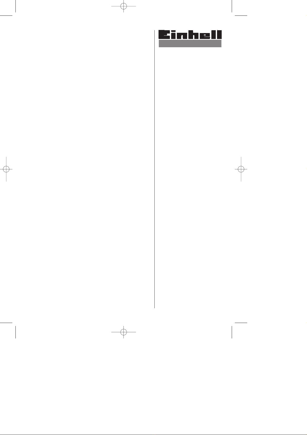
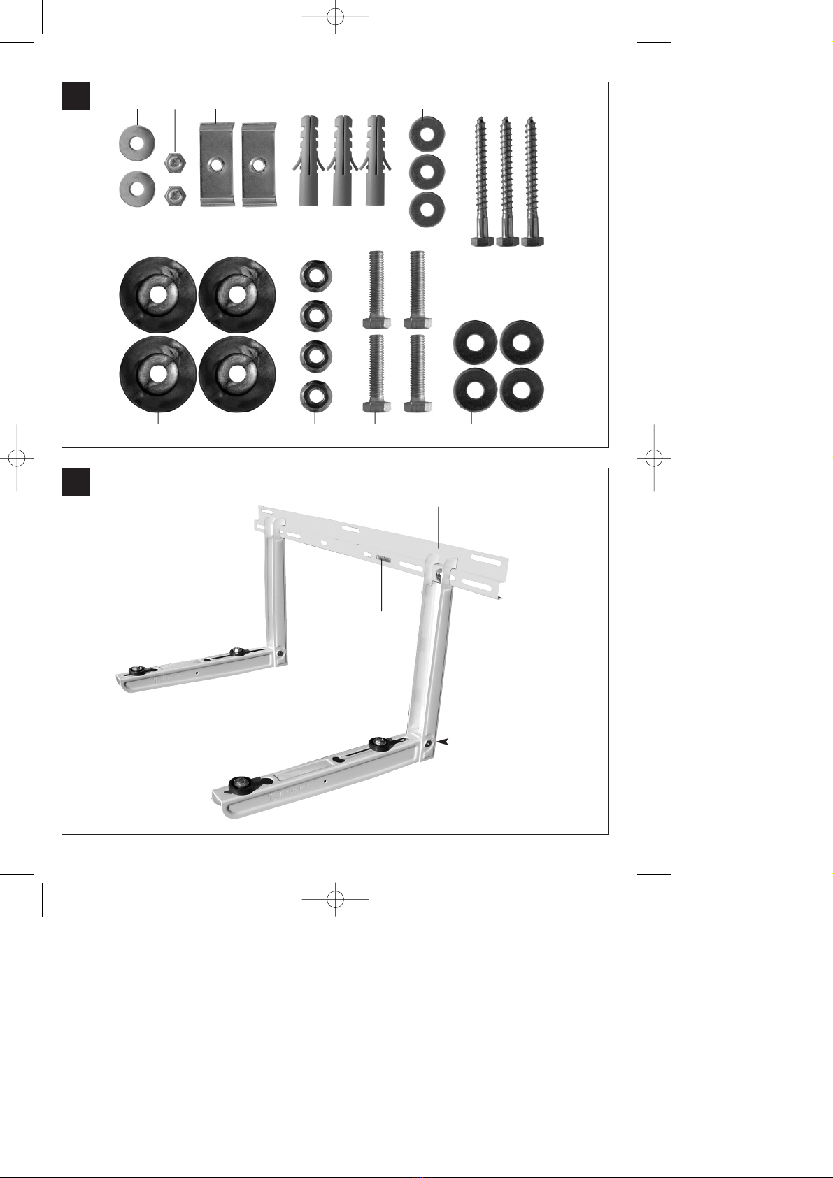
1. Lieferumfang (Abb. 1 / 2)
Pos. Bezeichnung Stückzahl
1 Wasserwaagenlibelle 1
2 Abstandshalter 2
3 Unterlegscheibe 8,4 2
4 Sechskantschraube M 8x10 2
5 Befestigungsblech 2
6 Dübel Ø 12mm 3
7 Unterlegscheibe 8,4 3
8 Sechskant - Holzschraube 3
9 Anti-Vibrationsgummi 4
10 Sechskantmutter mit Ansatz M8 4
11 Sechskantschraube M8x25 4
12 Unterlegscheibe 8,4 4
13 Montageschiene 1
14 Ausleger klappbar 2
2. Technische Daten
Ausladung ca.: 430 mm
Ausleger verschiebbar ca.: 350 – 760 mm
Tragkraft max.: 140 kg
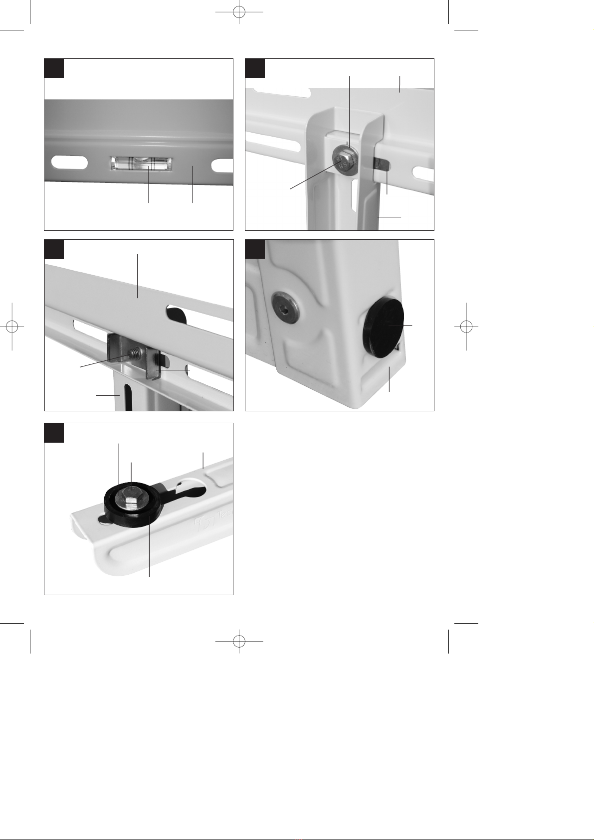
3. Zusammenbau
앬Abb. 3: Drücken Sie die Wasserwaagenlibelle (1)
in die Montageschiene (13).
앬Abb. 4 / 5: Verschrauben Sie die Ausleger (14)
mit der Montageschiene (13). Verwenden Sie
dazu das Befestigungsblech (5), Unterlegscheibe
(3) und die Sechskantschraube (4).
앬Abb. 6: Drücken Sie die Abstandshalter (2) in die
Aufnahme an der Auslegerrückseite (14).
앬Abb. 7: Schieben Sie die Anti-Vibrationsgummi
(9) auf den Ausleger (14), sodass sie mit den
Befestigungen des Klimaanlagenaußengerätes
zusammen passen. Schrauben Sie das
Klimaanlagenaußengerät mittels der
Sechskantschraube M (11), Unterlegscheibe (12)
und Sechskantmutter mit Ansatz (10) fest.
Hinweis: Die Abb. 7 zeigt die Verschraubung
ohne Außengerät.
4. Hinweise zur Wandmontage
a) Verwenden Sie nur geeignetes
Befestigungsmaterial.
Die mitgelieferten Dübel (6) und Schrauben (8)
sind geeignet für:
Beton, Naturstein mit dichtem Gefüge, Vollziegel,
Kalksand-Vollstein, Vollstein aus Leichtbeton,
Porenbeton (Gasbeton), Vollgips-Platten,
Hochlochziegel, Kalksand-Lochstein,
Hohlblockstein aus Leichtbeton.
b) Stellen Sie sicher, dass sich im Bereich der
Bohrlöcher keine elektrischen Leitungen oder
andere Installationen (z.B. Wasserrohre)
befinden. Achten Sie auf festen, waagerechten
Sitz der Konsole an der Wand. Die in der
Montageschiene integrierte Wasserwaage ist
Ihnen dabei behilflich.
D
4
Anleitung KWK 1_SPK7:_ 17.10.2007 15:21 Uhr Seite 4

1. Items supplied (Fig. 1 / 2)
Item Description Quantity
1 Spirit level 1
2 Separator 2
3 Washer 8,4 2
4 Hexagonal head screw M 8x10 2
5 Fastening plate 2
6 12 mm wall plug 3
7 Washer 8.4 3
8 Hexagonal head wood screw 3
9 Anti-vibration rubber 4
10 Hexagonal nut with shoulder M8 4
11 Hexagonal head screw M8x25 4
12 Washer 8.4 4
13 Mounting rail 1
14 Folding arm 2
2. Technical data
Outreach, approx. 430 mm
Arm adjustment, approx. 350 - 760 mm
Load capacity, max. 140 kg
3. Assembly
앬Fig. 3: Press the spirit level (1) into the mounting
rail (13).
앬Fig. 4 / 5: Screw the arm (14) to the mounting rail
(13). Use the fastening plate (5), washer (3) and
hexagonal head screw (4) for this purpose.
앬Fig. 6: Press the spacer (2) into the mounting on
the rear of the arm (14).
앬Fig. 7: Slide the anti-vibration rubbers (9) on to
the arm (14) so that they fit together with the
mountings on the outdoor air-conditioning
system. Secure the outdoor air-conditioning unit
using the hexagonal head screw M (11), washer
(12) and hexagonal nut with shoulder (10). Note:
Fig. 7 shows the screw connection without the
outdoor unit.
4. Instructions for wall mounting
a) Use only suitable fastening material.
The supplied plugs (6) and screws (8) are
suitable for concrete, natural stone with a dense
structure, solid bricks, solid lime-sand blocks,
solid blocks made of lightweight concrete, pore
concrete (gas concrete), solid gypsum panels,
perforated high blocks, perforated lime-sand
blocks and hollow blocks made of lightweight
concrete.
b) Make sure that there are no electric cables or
other installations (for example water pipes) near
the drill holes. Ensure that the bracket is firmly
and horizontally fitted to the wall. The spirit level
integrated in the mounting rail will help you
ensure this.
GB
5
Anleitung KWK 1_SPK7:_ 17.10.2007 15:21 Uhr Seite 5

1. Etendue de la livraison (fig. 1 / 2)
Pos. Désignation Nombre de pièces
1 Niveau à bulle 1
2 Ecarteur 2
3 Rondelle 8,4 2
4 Vis à tête hexagonale M 8X10 2
5 Tôle de fixation 2
6 Cheville Ø 12mm 3
7 Rondelle 8,4 3
8 Vis à six pans à bois 3
9 Gomme antivibratoire 4
10 Ecrou hexagonal avec embout M8 4
11 Boulon hexagonal M8x25 4
12 Rondelle 8,4 4
13 Rail de montage 1
14 Bras repliable 2
2. Données techniques
Portée environ : 430 mm
Bras coulissant environ : 350 – 760 mm
Capacité de charge maxi. : 140 kg
3. Assemblage
앬Fig. 3: Enfoncez le niveau à bulle (1) dans le rail
de montage (13).
앬Fig. 4 / 5 : Vissez les bras (14) au rail de montage
(13). Utilisez pour ce faire la tôle de fixation (5), la
rondelle (3) et la vis à tête hexagonale (4).
앬Fig. 6: Enfoncez l’écarteur (2) dans le logement
au dos du bras (14).
앬Fig. 7: Enfichez le joint antivibratoire (9) sur le
bras (14) de manière que les fixations sur
l’appareil extérieur de la climatisation
correspondent. Vissez l’appareil extérieur de la
climatisation à fond à l’aide de la vis à tête
hexagonale M (11), de la rondelle (12) et de
l’écrou à six pans avec embout (10). Remarque :
La fig. 7 montre le raccord vissé sans l’appareil
extérieur.
4. Consigne pour le montage mural
a) Utilisez exclusivement le matériel de fixation
adéquat.
Les chevilles (6) et vis (8) conviennent : au béton,
à la pierre naturelle à grainure fine, à la brique
pleine, à la brique pleine sillico-calcaire, à la
brique pleine en béton léger, au béton cellulaire
(béton-gaz), aux plaques de plâtre plein, à la
brique perforée, à la pierre perforée sillico-
calcaire et au bloc creux en béton léger.
b) Assurez-vous qu’aucun câble ni aucune
installation ne se trouve dans la zone des forures
(p. ex. des conduits d’eau). Veillez à bien fixer la
console au mur en position horizontale. Le niveau
à bulle d’air intégré au rail de montage vous
aidera.
F
6
Anleitung KWK 1_SPK7:_ 17.10.2007 15:21 Uhr Seite 6

1. Elementi forniti (Fig. 1/2)
Pos. Denominazione Quantità
1 Livella a bolla 1
2 Distanziatore 2
3 Rosetta 8,4 2
4 Vite a testa esagonale M 8x10 2
5 Listello in lamiera di fissaggio 2
6 Tassello Ø 12mm 3
7 Rosetta 8,4 3
8 Vite da legno a testa esagonale 3
9 Gomma antivibrante 4
10 Dado a testa esagonale con bordo M8 4
11 Vite a testa esagonale M8x25 4
12 Rosetta 8,4 4
13 Guida di montaggio 1
14 Braccio orientabile 2
2. Caratteristiche tecniche
Sbraccio ca.: 430 mm
Braccio spostabile ca.: 350 – 760 mm
Portata max.: 140 kg
3. Montaggio
앬Fig. 3 Premete la livella a bolla (1) nella guida di
montaggio (13).
앬Fig. 4 / 5 Avvitate il braccio (14) con la guida di
montaggio (13). Usate per questo il listello in
lamiera di fissaggio (5), la rosetta (3) e la vite a
testa esagonale (4).
앬Fig. 6 Premete i distanziatori (2) nella sede sul
retro del braccio (14).
앬Fig. 7 Spingete le gomme antivibranti (9) sul
braccio (14) in modo che corrispondano ai
fissaggi dell’apparecchio esterno climatizzatore.
Avvitate l’apparecchio esterno del climatizzatore
tramite la vite a testa esagonale M (11), la rosetta
(12) ed il dado a testa esagonale con il bordo
(10). Avvertenza: la Fig. 7 mostra il collegamento
a vite senza apparecchio esterno.
4. Avvertenze per il montaggio alla
parete
a) Usate solo materiale di fissaggio adeguato.
I tasselli (6) e le vite (8) forniti sono adatti per:
calcestruzzo, pietra naturale dalla struttura
compatta, mattoni pieni, mattoni pieni di arenaria
calcarea, mattoni pieni di calcestruzzo leggero,
calcestruzzo cellulare (poroso), lastra di gesso
massiccio, mattoni forati, mattoni forati di arenaria
calcarea, mattoni forati di calcestruzzo leggero.
b) Accertatevi che nella zona dei fori non ci siano
cavi elettrici o altre installazioni (per es. tubazioni
dell’acqua). Fate attenzione che la mensola sia
ben fissata alla parete allineata in orizzontale. La
livella integrata nella guida di montaggio vi é di
aiuto a tale scopo.
I
7
Anleitung KWK 1_SPK7:_ 17.10.2007 15:21 Uhr Seite 7

1. Omvang van de levering (fig. 1/2)
Pos. Benaming Aantal stuks
1 Waterpaslibel 1
2 Afstandshouder 2
3 Sluitring 8,4 2
4 Zeskantschroef M 8x10 2
5 Bevestigingsplaat 2
6 Plug Ø 12 mm 3
7 Sluitring 8,4 3
8 Zeskanthoutschroef 3
9 Antitrilrubber 4
10 Zeskantmoer met kraag M8 4
11 Zeskantschroef M8x25 4
12 Sluitring 8,4 4
13 Montagerail 1
14 Draagarm vouwbaar 2
2. Technische gegevens
Vlucht ca.: 430 mm
Draagarm verschuifbaar ca.: 350 – 760 mm
Draagkracht max.: 140 kg
3. Assemblage
앬Fig. 3: Druk de waterpaslibel (1) de montagerail
(13) in.
앬Fig. 4/5: Schroef de draagarmen (14) vast op de
montagerail (13). Gebruik daarvoor de
bevestigingsplaat (5), de sluitring (3) en de
zeskantschroef (4).
앬Fig. 6: Druk de afstandshouder (2) de opname
aan de achterkant van de draagarm (14) in.
앬Fig. 7: Schuif de antitrilrubberstukken (9) zodanig
op de draagarm (14) dat ze overeenkomen met
de bevestigingen van het buitenapparaat van de
airco. Schroef het buitenapparaat van de airco
vast d.m.v. de zeskantschroef M (11), de sluitring
(12) en de zeskantmoer met kraag (10).
Aanwijzing: Fig. 7 toont de schroefverbinding
zonder buitenapparaat.
4. Aanwijzingen omtrent de
muurmontage
a) Gebruik enkel geschikt bevestigingsmateriaal.
De bijgeleverde pluggen (6) en schroeven (8) zijn
geschikt voor: beton, natuursteen met compacte
textuur, massieve baksteen, massieve
kalkzandsteen, massieve baksteen in lichtbeton,
cellenbeton (gasbeton), massieve gipsplaten,
geperforeerde baksteen, geperforeerde
kalkzandsteen, holle blokken in lichtbeton.
b) Vergewis u er zich van dat in de buurt van de
boorgaten zich geen elektrische leidingen of
andere installaties (b.v. waterleidingen) bevinden.
Let erop dat de console goed vast en horizontaal
op de muur zit. Het in de montagerail
geïntegreerde waterpas is daarbij behulpzaam.
NL
8
Anleitung KWK 1_SPK7:_ 17.10.2007 15:21 Uhr Seite 8

1. Leveringsomfang (fig. 1 / 2)
Pos. Benævnelse Styktal
1 Lodstoklibelle 1
2 Afstandsstykke 2
3 Underlægsskive 8,4 2
4 Sekskantskrue M 8x10 2
5 Fastgøringsbeslag 2
6 Dyvler Ø 12mm 3
7 Underlægsskive 8,4 3
8 Sekskant - træskrue 3
9 Anti-vibrationsgummi 4
10 Sekskantmøtrik med ansats M8 4
11 Sekskantskrue M8x25 4
12 Underlægsskive 8,4 4
13 Monteringsskinne 1
14 Udligger, sammenklappelig 2
2. Tekniske data
Udhæng ca.: 430 mm
Udligger forskydelig ca.: 350 – 760 mm
Bæreevne maks.: 140 kg
3. Samling
앬Fig. 3: Pres lodstoklibellen (1) ind i
monteringsskinnen (13).
앬Fig. 4 / 5: Skru udliggerne (14) sammen med
monteringsskinnen (13). Brug hertil
fastgøringsbeslag (5), underlægsskive (3) og
sekskantskrue (4).
앬Fig. 6: Pres afstandsholderne (2) ind i indtaget på
bagsiden af udliggeren (14).
앬Fig. 7: Sæt anti-vibrationsgummiet (9) på
udliggeren (14), så gummiet passer sammen
med fastgøringerne på det udvendige
klimaanlæg. Skru det udvendige klimaanlæg fast
ved hjælp af sekskantskrue M (11),
underlægsskive (12) og sekskantmøtrik med
ansats (10). Bemærk: Fig. 7 viser skruesamlingen
uden udvendig enhed.
4. Anvisninger til vægmontering
a) Anvend kun egnet fastgøringsmateriale.
De medfølgende dyvler (6) og skruer (8) egner
sig til: Beton, natursten med tæt struktur, massiv
sten, massiv kalksandsten, massiv sten af
letbeton, cellebeton (gasbeton), massive
gipsplader, mangehulsten, gennemhullet
kalksandsten, hulblok af letbeton.
b) Kontroller, at der ikke er elektriske ledninger eller
andre installationer i området omkring
borehullerne (f.eks. vandrør). Sørg for, at
konsollen sidder godt fast på væggen i vandret
position. Brug her lodstokken, som er integreret i
monteringsskinnen, som hjælp.
DK/N
9
Anleitung KWK 1_SPK7:_ 17.10.2007 15:21 Uhr Seite 9

1. Leveransomfattning (bild 1/2)
Pos. Beteckning Antal
1 Vattenpasslibell 1
2 Avståndshållare 2
3 Distansbricka 8,4 2
4 Sexkantskruv M8x10 2
5 Monteringsplåt 2
6 Plugg Ø 12 mm 3
7 Distansbricka 8,4 3
8 Sexkantträskruv 3
9 Anti-vibrationsgummi 4
10 Sexkantmutter med ansats M8 4
11 Sexkantskruv M8x25 4
12 Distansbricka 8,4 4
13 Monteringsskena 1
14 Vikbar bom 2
2. Tekniska data
Svängradie ca 430 mm
Bom förskjutbar ca 350 – 760 mm
Bärförmåga max. 140 kg
3. Montera samman konsolen
앬Bild 3: Tryck in vattenpassenlibellen (1) i
monteringsskenan (13).
앬Bild 4/5: Förskjut bommen (14) med
monteringsskenan (13). Använd
monteringsplåten (5), distansbrickan (3) och
sexkantskruven (4).
앬Bild 6: Tryck in avståndshållaren (2) i fästet på
bommens baksida (14).
앬Bild 7: Skjut anti-vibrationsgummin (9) på
bommen (14) så att de passar samman med
fästet till klimatanläggningens utomhusdel.
Skruva fast klimatanläggningens utomhusdel
med sexkantskruv M (11), distansbricka (12) och
sexkantmutter med ansats (10). Obs! I bild 7
visas fastskruvningen utan utomhusdel.
4. Information om väggmontering
a) Använd endast lämpligt monteringsmaterial.
Medföljande pluggar (6) och skruvar (8) är
lämpliga för: betong, natursten med tät struktur,
heltegel, kompakt kalksandsten, kompakt
lättbetong, porbetong (gasbetong), kompakta
gasskivor, håltegel, ihålig kalksandsten, hålblock
av lättbetong.
b) Kontrollera att inga elektriska ledningar eller
andra installationer (t ex vattenrör) finns inom de
områden där borrhålen ska göras. Se till att
konsolen sitter stabilt och vågrätt på väggen.
Vattenpasset som finns i monteringsskenan kan
vara till hjälp.
S
10
Anleitung KWK 1_SPK7:_ 17.10.2007 15:21 Uhr Seite 10

1. Toimituksen laajuus (kuvat 1 / 2)
Kohta Nimike Lukumäärä
1 Vesivaaka 1
2 Erotuskappale 2
3 Aluslevy 8,4 2
4 Kuusikulmaruuvi M 8 x 10 2
5 Kiinnityspelti 2
6 Vaarna Ø 12 mm 3
7 Aluslevy 8,4 3
8 Kuusikulmapuuruuvi 3
9 Tärinänvaimennuskumi 4
10 Kuusikulmamutteri M8 kannalla 4
11 Kuusikulmaruuvi M8 x 25 4
12 Aluslevy 8,4 4
13 Asennuskisko 1
14 Puomi, käännettävä 2
2. Tekniset tiedot
Ulkonema n.: 430 mm
Puomi työnnettävissä n.: 350 – 760 mm
Kantavuus kork.: 140 kg
3. Kokoaminen
앬Kuva 3: Paina vesivaaka (1) paikalleen
asennuskiskoon (13).
앬Kuvat 4 / 5: Ruuvaa puomi (14) kiinni
asennuskiskoon (13). Käytä tässä kiinnityspeltiä
(5), aluslevyä (3) ja kuusikulmaruuvia (4).
앬Kuva 6: Paina erotuskappaleet (2) paikoilleen
puomin takasivulle (14).
앬Kuva 7: Työnnä tärinänestokumit (9) puomin (14)
päälle niin, että ne sopivat yhteen
ilmastointilaitteiston ulkolaitteen kiinnikkeiden
kanssa. Ruuvaa ilmastointilaitteiston ulkolaite
kuusikantaruuvin M (11), aluslevyn (12) ja
kannallisen kuusikulmamutterin (10) kera kiinni
paikalleen. Viite: Kuva 7 esittää ruuvikiinnitystä
ilman ulkolaitetta.
4. Ohjeita seinäasennusta varten
a) Käytä vain tarkoitukseen sopivia
kiinnitystarvikkeita.
Mukana toimitetut vaarnat (6) ja ruuvit (8)
soveltuvat seuraaviin materiaaleihin: betoni,
tiivisrakenteinen luonnonkivi, umpitiili, kalkkikivi-
umpikivi, kevytbetoni-umpikivi, solubetoni
(kaasubetoni), umpikipsilevyt, reikätiili, kalkkikivi-
reikäkivi, kevytbetoni-reikätiili.
b) Varmista, että porausreikien alueella ei ole
sähköjohtoja tai muita asennuksia (esim.
vesijohtoja). Huolehdi siitä, että konsoli on
seinällä tukevasti vaakasuorassa.
Asennuskiskoon sisäänrakennettu vesivaaka on
tässä avuksi.
FIN
11
Anleitung KWK 1_SPK7:_ 17.10.2007 15:21 Uhr Seite 11

1. Rozsah dodávky (obr. 1 / 2)
Pol. Označení Počet kusů
1 Libela vodováhy 1
2 Rozpěrka 2
3 Podložka 8,4 2
4 Šroub se šestihrannou hlavou M 8x10 2
5 Upevňovací plech 2
6 Hmoždinka Ø 12mm 3
7 Podložka 8,4 3
8 Vrut se šestihrannou hlavou 3
9 Antivibrační pryž 4
10 Šestihranná matice s nákružkem M8 4
11 Šroub se šestihrannou hlavou M8x25 4
12 Podložka 8,4 4
13 Montážní lišta 1
14 Konsola sklápěcí 2
2. Technická data
Vyložení cca: 430 mm
Konsola posuvná cca: 350 - 760 mm
Nosnost max.: 140 kg
3. Montáž
앬Obr. 3: Zatlačte libelu vodováhy (1) do montážní
lišty (13).
앬Obr. 4 / 5: Sešroubujte konsoly (14) s montážní
lištou (13). Použijte k tomu upevňovací plech (5),
podložku (3) a šroub se šestihrannou hlavou (4).
앬Obr. 6: Zatlačte rozpěrky (2) do upínání na zadní
straně konsoly (14).
앬Obr. 7: Nasuňte antivibrační pryže (9) na konsolu
(14) tak, aby se shodovaly s upevněními vnější
jednotky klimatizace. Utáhněte vnější jednotku
klimatizace pomocí šroubu se šestihrannou
hlavou M (11), podložky (12) a šestihranné
matice s nákružkem (10). Pokyn: Obr. 7 ukazuje
šroubové spojení bez vnější jednotky klimatizace.
4. Pokyny k montáži na zeď
a) Použijte pouze vhodný upevňovací materiál.
Dodané hmoždinky (6) a šrouby (8) jsou vhodné
pro: beton, přírodní kámen s hustou texturou,
plné cihly, vápenopískové plné tvárnice, plné
tvárnice z lehkého betonu, pórobeton
(plynobeton), plné sádrové desky, příčně
děrované cihly, vápenopískové dutinové tvárnice,
duté tvárnice z lehkého betonu.
b) Přesvědčte se, že se v oblasti vyvrtaných děr
nenacházejí žádná elektrická vedení nebo jiné
instalace (např. vodovodní trubky). Dbejte na
pevné, vodorovné umístění konsoly na zdi. K
tomu Vám pomůže vodováha integrovaná v
montážní liště.
CZ
12
Anleitung KWK 1_SPK7:_ 17.10.2007 15:21 Uhr Seite 12

1. Obseg dobave (Slika 1 / 2)
Poz. Opis Količina
1 Vodna tehtnica 1
2 Distančnik 2
3 Podložka 8,4 2
4 Šestrobni vijak M 8x10 2
5 Pločevina za pritrditev 2
6 Stenski vložek Ø 12 mm 3
7 Podložka 8,4 3
8 Šestrobni lesni vijak 3
9 Protivibracijski gumi 4
10 Šestrobna matica z nastavkom M8 4
11 Šestrobni vijak M8x25 4
12 Podložka 8,4 4
13 Montažni kovinski trak 1
14 Zložljivi nosilec 2
2. Tehnični podatki
Pomolek ca.: 430 mm
Nosilec, nastavljiv ca.: 350 – 760 mm
Nosilnost max.: 140 kg
3. Sestava
앬Slika 3: Pritisnite vodno tehtnico (1) v montažni
kovinski trak (13).
앬Slika 4 / 5: Privijte nosilce (14) na montažni
kovinski trak (13). Pri tem uporabite pločevino za
pritrditev (5), podložko (3) in šestrobni vijak (4).
앬Slika 6: Pritisnite distančnike (2) v sprejemni del
na zadnji strani nosilca (14).
앬Slika 7: Potisnite protivibracijske gumice (9) na
nosilce (14) tako, da se bodo ujemali s
pritrditvami zunanje klimatske naprave. Privijte
zunanjo klimatsko napravo s šestrobnim vijakom
M (11), podložko (12) in šestrobno matico z
nastavkom (10). Napotek: slika 7 prikazuje
privijanje brez zunanje naprave.
4. Napotki za stensko montažo
a) Uporabljajte samo primerni material za pritrditev.
Priloženi stenski vložki (6) in vijaki (8) so primerni
za: beton, naravni kamen goste strukture, polno
opeko, polni zidaki iz apnenca, polni zidak iz
lahkega betona, luknjičasti beton (plinasti beton),
mavčne plošče, votla opeka, votli zidaki iz
apnenca, votli betonski zidaki iz lahkega betona.
b) Preverite, če se v območju vrtanja lukenj ne
nahaja električna napeljava ali druga instalacija
(n.pr. vodovodne cevi). Pazite na čvrsti,
vodoravni položaj konzole na steni. V ta namen
Vam bo v pomoč v montažnem kovinskem traku
vstavljena vodna tehtnica.
SLO
13
Anleitung KWK 1_SPK7:_ 17.10.2007 15:21 Uhr Seite 13

1. Objem dodávky (obr. 1 / 2)
Pol. Označenie Počet kusov
1 Libela vodováhy 1
2 Distančný diel 2
3 Podložka 8,4 2
4 Šesťhranná skrutka M 8x10 2
5 Upevňovací plech 2
6 Hmoždinka Ø 12 mm 3
7 Podložka 8,4 3
8 Vrut so šesťhrannou hlavou 3
9 Antivibračná guma 4
10 Šesťhranná matica s nábehom M8 4
11 Šesťhranná skrutka M8x25 4
12 Podložka 8,4 4
13 Montážna lišta 1
14 Konzola sklopná 2
2. Technické údaje
Vyloženie cca: 430 mm
Konzola posuvná cca: 350 -760 mm
Nosnosť max.: 140 kg
3. Montáž
앬Obr. 3: Zatlačte libelu vodováhy (1) do montážnej
lišty (13).
앬Obr. 4 / 5: Zoskrutkujte konzoly (14) s montážnou
lištou (13). Použite na to upevňovací plech (5),
podložku (3) a šesťhrannú skrutku (4).
앬Obr. 6: Zatlačte distančné diely (2) do uloženia na
zadnej strane konzoly (14).
앬Obr. 7: Nasuňte antivibračnú gumu (9) na
konzolu (14) tak, aby bola v správnej polohe voči
upevneniu vonkajšieho prístroja klimatizácie.
Pevne priskrutkujte vonkajší prístroj klimatizácie
pomocou šesťhrannej skrutky M (11), podložky
(12) a šesťhrannej matice s nábehom (10).
Upozornenie: Obr. 7 znázorňuje skrutkový spoj
bez vonkajšieho prístroja.
4. Pokyny pre montáž na stenu
a) Používajte len vhodný upevňovací materiál.
Dodané hmoždinky (6) a skrutky (8) sú vhodné
pre: betón, prírodný kameň s tesným spojením,
plné tehly, plnú vápencovú tvárnicu, tvárnicu
z ľahkého betónu, pórobetón (plynový betón),
plné sadrokartónové dosky, priečne dierované
tehly, vápenno-pieskovú dutinovú tvárnicu,
dutinovú tvárnicu z ľahkého betónu.
a) Zabezpečte, aby v oblasti určenej na vŕtanie dier
neboli žiadne elektrické vedenia ani iné inštalácie
(napr. vodovodné potrubia). Dbajte na pevné,
vodorovné pripevnenie konzoly na stenu. Pritom
Vám pomôže vodováha integrovaná do
montážnej lišty.
SK
14
Anleitung KWK 1_SPK7:_ 17.10.2007 15:21 Uhr Seite 14

1. Sevkiyatın içeriği (Şekil 1 / 2)
Poz. Tanım Adet
1 Su terazisi 1
2 Aralık tutma elemanı 2
3 Rondela 8,4 2
4 Civata M 8x10 2
5 Bağlantı sacı 2
6 Dübel Ø 12mm 3
7 Rondela 8,4 3
8 Ağaç civatası 3
9 Anti vibrasyon lastiği 4
10 Halkalı somun M8 4
11 Civata M8x25 4
12 Rondela 8,4 4
13 Montaj kızağı 1
14 Katlanır travers 2
2. Teknik özellikler:
Travers açıklığı yakl.: 430 mm
Travers kaydırılabilir yakl.: 350 – 760 mm
Taşıma kuvveti max.: 140 kg
3. Montaj
앬Şekil 3: Su terazisini (1) montaj kızağı (13) içine
bastırarak takın.
앬Şekil 4 / 5: Traversi (14) montaj kızağına (13)
civata ile bağlayın. Bunun için bağlantı sacı (5),
rondela (3) ve civatayı (4) kullanın.
앬Şekil 6: Aralık tutma elemanını (2) traversin arka
tarafındaki yuva (14) içine yerleştirin.
앬Şekil 7: Anti vibrasyon lastiğini (9) travers üzerine
(14), klima cihazının dış ünitesinin bağlantı yerleri
ile aynı hizada olacak şekilde yerleştirin. Klima
cihazının dış ünitesini civata M (11), rondela (12)
ve halkalı somun (10) ile sıkıca bağlayın. Uyarı:
Şekil 7’de klima cihazının dış ünitesinin
bulunmadığı durum gösterilmiştir.
4. Duvar montajı ile ilgili uyarılar
a) Sadece uygun bağlantı malzemesi kullanın.
Konsol ile birlikte gönderilmiş olan dübel (6) ve
civatalar (8) şu bağlantı yerlerine yapılacak
montaj uygulaması için uygundur: Beton, yoğun
yapılı doğal taş, dolu tuğla, kiraç taşından
üretilmiş dolu tuğla, hafif beton dolu tuğlası,
gözenekli beton (gazbeton), dolu alçıpan, dikey
delikli tuğla, kiraç taşından üretilmiş delikli tuğla,
hafif beton delikli tuğla.
b) Delik delinecek yerden elektrik tesisatı veya diğer
tesisatların (örneğin su boruları) geçmemesini
sağlayın. Klima konsolunun duvara tam yatay
pozisyonda monte edilmesine dikkat edin. Tam
doğru yatay pozisyonun sağlanması için montaj
kızağındaki su terazisi size yardımcı olur.
TR
15
Anleitung KWK 1_SPK7:_ 17.10.2007 15:21 Uhr Seite 15

16
Der Nachdruck oder sonstige Vervielfältigung von Dokumentation und
Begleitpapieren der Produkte, auch auszugsweise ist nur mit aus-
drücklicher Zustimmung der ISC GmbH zulässig.
The reprinting or reproduction by any other means, in whole or in part,
of documentation and papers accompanying products is permitted only
with the express consent of ISC GmbH.
La réimpression ou une autre reproduction de la documentation et des
documents dʼaccompagnement des produits, même incomplète, nʼest
autorisée quʼavec lʼagrément exprès de lʼentreprise ISC GmbH.
La ristampa o lʼulteriore riproduzione, anche parziale, della
documentazione o dei documenti dʼaccompagnamento dei prodotti è
consentita solo con lʼesplicita autorizzazione da parte della ISC GmbH.
Nadruk of andere reproductie van documentatie en geleidepapieren
van de producten, geheel of gedeeltelijk, enkel toegestaan mits
uitdrukkelijke toestemming van ISC GmbH.
Eftertryk eller anden form for mangfoldiggørelse af skriftligt materiale,
ledsagepapirer indbefattet, som omhandler produkter, er kun tilladt
efter udtrykkelig tilladelse fra ISC GmbH.
Eftertryck eller annan duplicering av dokumentation och medföljande
underlag för produkter, även utdrag, är endast tillåtet med uttryckligt
tillstånd från ISC GmbH.
q
Tuotteiden dokumentaatioiden ja muiden mukaanliitettyjen asiakirjojen
vain osittainenkin kopiointi tai muunlainen monistaminen on sallittu
ainoastaan ISC GmbH:n nimenomaisella luvalla.
j
Dotisk nebo jiné rozmnožování dokumentace a průvodních
dokumentů výrobků, také pouze výňatků, je přípustné výhradně se
souhlasem firmy ISC GmbH.
X
Ponatis ali druge vrste razmnoževanje dokumentacije in spremljajočih
dokumentov proizvodov proizvajalca, tudi v izvlečkih, je dovoljeno
samo z izrecnim soglasjem firme ISC GmbH.
W
Kopírovanie alebo iné rozmnožovanie dokumentácie a sprievodných
podkladov produktov, a to aj čiastočné, je prípustné len s výslovným
povolením spoločnosti ISC GmbH.
Ürünlerinin dokümantasyonu ve evraklar∂n∂n k∂smen olsa dahi
kopyalanmas∂ veya baμka μekilde ço©alt∂lmas∂, yaln∂zca ISC GmbH
firmas∂n∂n özel onay∂ al∂nmak μart∂yla serbesttir.
Anleitung KWK 1_SPK7:_ 17.10.2007 15:21 Uhr Seite 16

17
Technische Änderungen vorbehalten
Technical changes subject to change
Sous réserve de modifications
Con riserva di apportare modifiche tecniche
Technische wijzigingen voorbehouden
Der tages forbehold för tekniske ændringer
Förbehåll för tekniska förändringar
qOikeus teknisiin muutoksiin pidätetään
jTechnické změny vyhrazeny
XTehnične spremembe pridržane.
WTechnické změny vyhradené
Teknik de©iμiklikler olabilir
Anleitung KWK 1_SPK7:_ 17.10.2007 15:21 Uhr Seite 17

18
Anleitung KWK 1_SPK7:_ 17.10.2007 15:21 Uhr Seite 18

19
Anleitung KWK 1_SPK7:_ 17.10.2007 15:21 Uhr Seite 19

20
tGUARANTEE CERTIFICATE
Dear Customer,
All of our products undergo strict quality checks to ensure that they reach you in perfect condition. In the unlikely
event that your device develops a fault, please contact our service department at the address shown on this
guarantee card. Of course, if you would prefer to call us then we are also happy to offer our assistance under
the service number printed below. Please note the following terms under which guarantee claims can be made:
1. These guarantee terms cover additional guarantee rights and do not affect your statutory warranty rights.
We do not charge you for this guarantee.
2. Our guarantee only covers problems caused by material or manufacturing defects, and it is restricted to the
rectification of these defects or replacement of the device. Please note that our devices have not been
designed for use in commercial, trade or industrial applications. Consequently, the guarantee is invalidated
if the equipment is used in commercial, trade or industrial applications or for other equivalent activities. The
following are also excluded from our guarantee: compensation for transport damage, damage caused by
failure to comply with the installation/assembly instructions or damage caused by unprofessional
installation, failure to comply with the operating instructions (e.g. connection to the wrong mains voltage or
current type), misuse or inappropriate use (such as overloading of the device or use of non-approved tools
or accessories), failure to comply with the maintenance and safety regulations, ingress of foreign bodies
into the device (e.g. sand, stones or dust), effects of force or external influences (e.g. damage caused by
the device being dropped) and normal wear resulting from proper operation of the device.
The guarantee is rendered null and void if any attempt is made to tamper with the device.
3. The guarantee is valid for a period of 2 years starting from the purchase date of the device. Guarantee
claims should be submitted before the end of the guarantee period within two weeks of the defect being
noticed. No guarantee claims will be accepted after the end of the guarantee period. The original guarantee
period remains applicable to the device even if repairs are carried out or parts are replaced. In such cases,
the work performed or parts fitted will not result in an extension of the guarantee period, and no new
guarantee will become active for the work performed or parts fitted. This also applies when an on-site
service is used.
4. In order to assert your guarantee claim, please send your defective device postage-free to the address
shown below. Please enclose either the original or a copy of your sales receipt or another dated proof of
purchase. Please keep your sales receipt in a safe place, as it is your proof of purchase. It would help us if
you could describe the nature of the problem in as much detail as possible. If the defect is covered by our
guarantee then your device will either be repaired immediately and returned to you, or we will send you a
new device.
Of course, we are also happy offer a chargeable repair service for any defects which are not covered by the
scope of this guarantee or for units which are no longer covered. To take advantage of this service, please send
the device to our service address.
Anleitung KWK 1_SPK7:_ 17.10.2007 15:21 Uhr Seite 20
This manual suits for next models
1
Table of contents
Languages: