HealthyAire HA-SCP-G3-W User manual

Source Capture
Air Purification System
HA-SCP-G3
Owner’s Manual
Table of Contents
HealthyAir® HA-IFM-1111 Filter
1
Important Safety Instructions
2
Technical Specifications
3
Packaging Reference
4
Packing Notice
5
Component Reference
6
Assembly Instructions
7-11
Operation Guidelines
12-13
Filter Replacement
14-16
Maintenance
17
Basic Service and Troubleshooting
18-22
Electrical Wiring Schematic
23
1-Yeart Limited Warranty
24
Product Registration Form
25
Distributed by
Aerovex Systems, Inc.
800-288-2023
www.aerovexsystems.com

1
HealthyAir®Model HA-SCP-G3
Source Capture Air Purification System
with
HealthyAir®HA-IFM-1111 Filter
at
www.aerovexsystems.com

2
WARNING
Unplug the power cord before servicing or replacing filters. Failure
to do so could result in serious personal injury and death.
I. Important Safety Instructions
Read the Owner's Manual and Important Safety Instructions carefully. Failure to
follow these instructions could cause a malfunction of the filter or unsatisfactory
performance. Follow a regular service and maintenance schedule for efficient
operation.
To reduce the risk of electric shock, fires, and/or injury:
•Do not use the air purifier in wet or damp locations
•Do not use outdoors
•Do not use at ambient temperature of above 95°F/35°C
•Do not use fabrics or other material to cover the inlet and outlet of the unit
•Do not allow children to operate or play with the unit
For safety reasons and to prevent electric shock, unplug the power cord from the
electric outlet socket under the following conditions:
•When not in use for a long period of time
•When cleaning, servicing the machine or during replacement of filters
•When moving the air purifier
To prevent electric shock, do not dismantle, repair or modify this product.
Maintenance and cleaning instructions should be followed exactly as directed in
this manual. In case of malfunction, please contact an authorized distributor or
Healthy Air Inc. for service instructions.
To reduce the risk of electric shock, the equipment has a grounding type plug that
has a third (grounding) pin. This plug will only fit into a grounding type power
outlet. If the plug does not fit into the outlet, contact qualified personnel to install
the proper outlet. Do not alter the plug in any way.
To reduce the risk of electric shock, do not pull the cord to remove the plug from
its outlets. Protect the cord against heat, oil and sharp objects. Do not run any
appliance over the cord. Do not pull or carry by the cord, use cord as a handle,
close a door on the cord, or pull cord around sharp edges or corners.

3
II. Technical Specifications
Model Number
HA-SCP-G3-W/B/G
Rated Voltage
120V/60HZ
Power Consumption
200W
Weight
37 lbs. (17 kg)
Base Dimensions
14x12x24 in. (350×310×615 mm)
Flex Hose Length
45 in. (114.3 cm)
Air Flow Rate
240 cfm (400 m3/h)
Noise Level
56 dB

4
III. Packaging Reference
The Source Capture Air Purification System is shipped in two (2) cartons, as
follows:
Carton 1: (1) Source Capture Air Purification Unit w/ (1) Integrated Filter
Module, (4) Wheel Casters, (1) Acoustic Mat, (1) Remote
Control, (1) Power Cord, (1) Screwdriver, (1) Manual
Carton 2: (1/2) Flex Hose + Hood, (1/2) Hose Clamp, (1/2) Grill + LED Cable
+ LED Bulb (Optional)
5
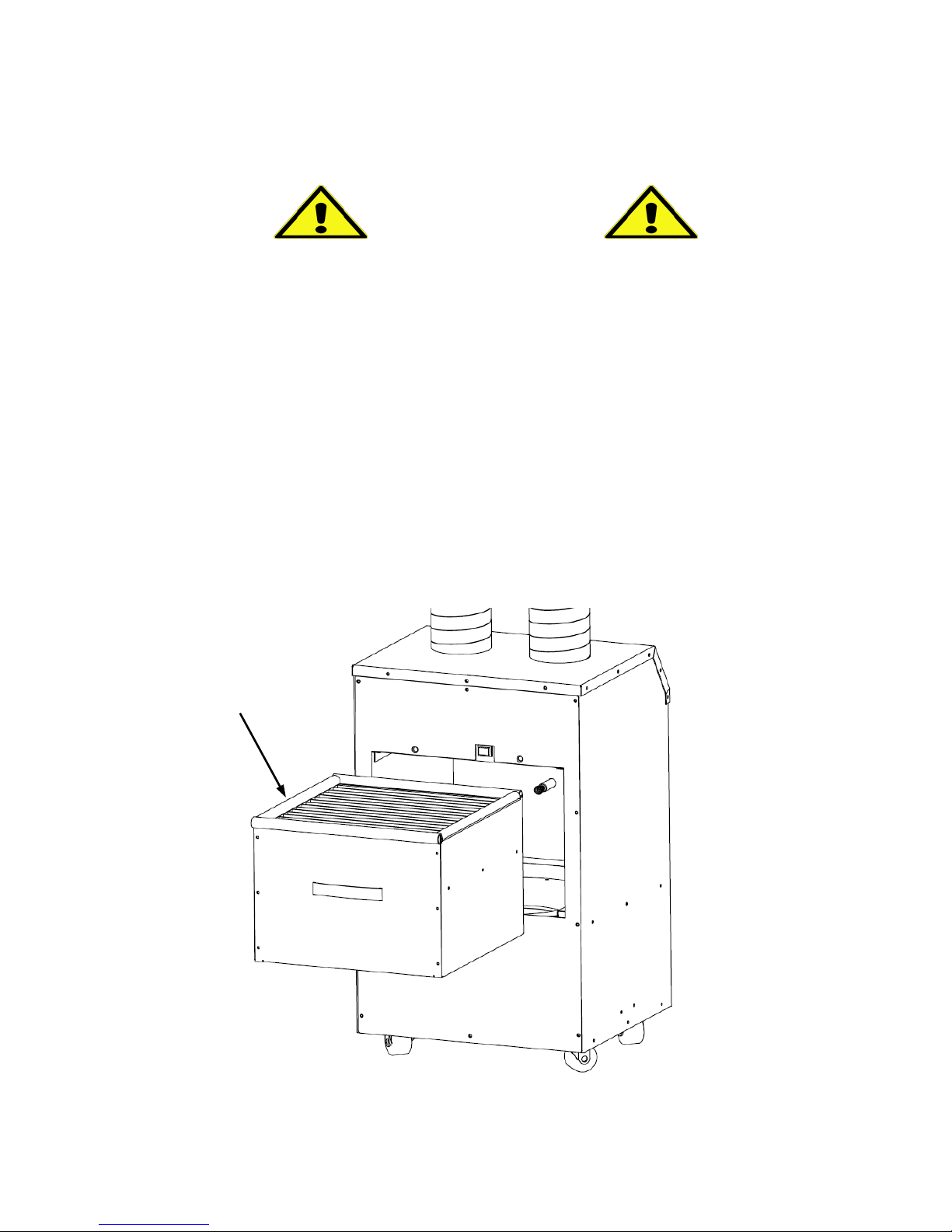
IV. Packaging Notice
NOTICE
Before operating the machine, do the following:
1. Open the Access Door (Refer to Section 8.2)
2. Remove the Integrated Filter Module (HA-IFM-1111)
3. Remove the plastic wrapping from the filter!
4. Re-install the Integrated Filter Module
5. Replace and secure the Access Door
Remove plastic wrapping
from Integrated Filter
Module prior to use!

6
V. Component Reference
1. Outer Frame
2. Acoustic Mat
3. Blower/Motor
4. Metal Screen
5. Caster Wheels
6. Bottom Plate
7. Motor Mount Plate
8. Baffle Plate
9. Air Inlet Guide
10. Integrated Filter Module
11. Activated Carbon Filter
12.eHEPA®Filter
13. eGrid
14.Silicon Seal
15. Pre-Filter
16. HV PCB
17.Switch
18. Capacitor
19. PCB
20. Flex Hose
21.LED
22. Hood
23. G4 Bulb Mount (Option)
24. LED Grill (Option)
25.LED Cable Plug (Option)
26.LED Cable Socket
27. Inlet Tube
28. Control Panel Display
29. Control Panel
30. Plastic Screw
31.HV Contact Spring
32. Power Cord
33. Remote Control

7
VI.Assembly Instructions
6.1 Install Caster Wheels
The following procedure is for Standard Application of the unit, whereby purified
air is vented through the Base Plate and recirculated within the facility.
For Outside Vent Applications, in which purified air is vented out of the facility,
skip Section 6.1 and refer to the wheel installation instructions in Section 6.4.
6.1.1 Place the unit on its side on a flat surface, as shown in Fig. 1.
6.1.2 Locate the four (4) Caster Wheels and the Screwdriver that are
provided in Carton 1.
6.1.3 Unscrew and remove the screws that are pre-mounted onto the Base
Plate, on the bottom of the unit. There are four (4) screws per wheel,
for a total of sixteen (16) screws.
6.1.4 Align the holes of the Caster Wheel Mount with the holes on the Base
Plate, and use four (4) screws to securely mount each Caster Wheel to
the Base Plate one by one.
Fig. (1) –Caster Wheel Installation
Base Plate
(16) Screws for
mounting wheels
8
VI.Assembly Instructions
6.2 Install LED Lighting (Optional)
Note that, the LED Lighting system is an optional feature. To add this feature,
visit www.aerovexsytems.com and
If LED Lighting was not purchased, skip section and proceed to Section 6.3.
6.2.1 Mount the LED Light Bulb on the Grill, by inserting the lip of the bulb
into the 4-piece cylinder located in the center of the Grill.
6.2.2 Connect the LED Cable to the LED Light Bulb, by sliding the two (2)
prongs of the bulb into the G4 Bulb Mount.
6.2.3 Pass the 52” LED Cable through the Hood and entire length of the Flex
Hose, such that the LED Cable Plug passes through the bottom of the
Flex Hose.
6.2.4 Connect the Grill to the Hood by snapping the Grill onto the rim of the
Hood, as shown in Fig. 2.
6.2.5 Connect the LED Cable Plug to the LED Cable Socket of the LED
Cable that is fixed to the edge of the Inlet Port.
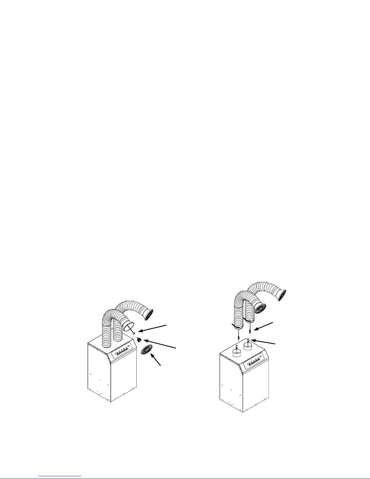
Fig. (2) –LED Lighting Installation
Grill
LED
Bulb
LED Cable w/
Bulb Mount
LED Cable
Plug
LED Cable
Socket

9
VI.Assembly Instructions
6.3 Install Flex Hose
The Flex Hose is constructed of interlocking bands that enable its length and
shape to be adjusted. Note that, the Flex Hose will unravel if it is lengthened or
bent past its tolerance point. The diameter of the Flex Hose can be also
adjusted by 10% by rotating sections of the hose counterclockwise.
6.3.1 Install the Flex Hose on the unit by sliding the end of the Flex Hose over
the Inlet Port, as shown in Fig. 3.
If the diameter of the Flex Hose needs to be increased, rotate the end
of the hose counterclockwise.
6.3.2 Hold the end of the Flex Hose and rotate it clockwise, to reduce its
diameter, to fit it to the diameter of the Inlet Port.
6.3.3 Position the Hose Clamp at the base of the Flex Hose, and screw the
hex nut to tighten the Hose Clamp and secure the Flex Hose on the
Inlet Port. Ensure that the connection is tight to optimize performance.
Fig. (3) –Flex Hose Installation
Hood
Inlet Port
Grill w/
LED Light
(Optional)
Flex Hose
Hose
Clamp
10
VI.Assembly Instructions
6.4 Install Outside Vent Adapter (Optional)
Note that, the Outside Vent Adapter is an optional feature. To add this feature,
visit www.aerovexsystems.com.
The Outside Vent Adapter comes with one (1) Outlet Flange, one (1) Outlet
Port Cover Plate, and has two (2) Outlet Ports, that enable it to exhaust air
from the back or side depending on which configuration is preferred.
6.4.1 If the Caster Wheels were initially installed on the unit, as described in
Section 6.1, remove each Caster Wheel from the Base Plate, and set
aside the wheels and the mounting screws.
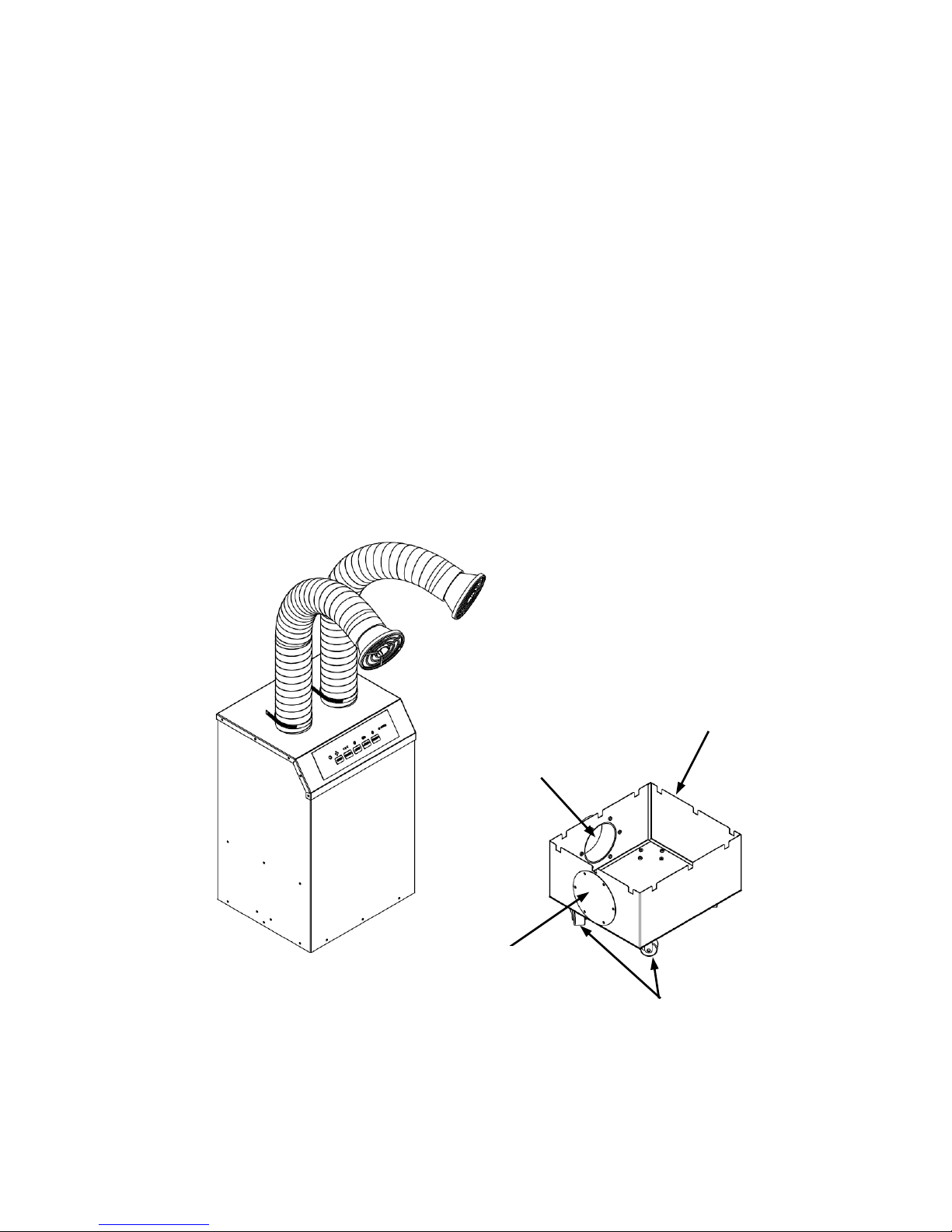
Fig. (4) –Outside Vent Adapter
Outside Vent Adapter
Caster Wheel
Outlet Port
Outlet Port
Cover Plate

11
VI.Assembly Instructions
6.5 Install Outside Vent Adapter (Optional)
6.5.1 Re-install each of the four (4) Caster Wheels to the bottom of the
Outside Vent Adapter, as shown in Fig. 4.
6.5.2 Install the Outlet Flange on one of the Outlet Ports, based a
determination of the ideal setup configuration.
6.5.3 Install the Outlet Port Cover Plate on the Outlet Port that is not being
used. Ensure that the Outlet Port Cover Plate is secure, such that the
seal between the plate and adapter is airtight.
6.5.4 Place the HealthyAir®Source Capture Air Purification System atop the
Outside Vent Adapter, as shown in Fig. 5.
6.5.5 Connect a standard 4’’ diameter Exhaust Duct (not supplied) to the
Outlet Flange of the Outside Vent Adapter, and use a standard hose
clamp to secure the connection.
6.5.6 Run the Exhaust Duct out of the facility per applicable IMC codes.
Fig. (5) –Outside Vent Adapter Installation
Outside
Vent
Adapter
Outlet
Flange
Exhaust
Duct
Outlet Port
Cover Plate

12
VII. Operation Guidelines
7.1 Source Capture System Positioning
Place the HealthyAir®Source Capture Air Purification System in the desired
location and place it on the Acoustic Mat to dampen the sound. Once the unit
is in place, adjust the Flex Hose to position the Hood approximately 6” from the
source of the particulate and fumes.
7.2 Source Capture System Activation
7.2.1 Plug the Power Cord into the Power Socket, located on the bottom of
the side panel of the unit, and then plug the other end of the cord into a
wall power socket.
Once plugged in, the Power indicator light [ ] will turn on and
display a red light.
7.2.2 Activate the unit by pressing the Power button located on the Control
Panel, shown in Fig. 6, or on the Remote Control.
Once the unit is powered, the motor will start with the Fan Speed set to
the Mid-Speed and the eHEPA® indicator will light up and display a
green light, which indicates that the eHEPA® system is activate.
7.3 Source Capture System Controls
Each of the respective control elements shown on the Control Panel Display in
Fig. 6 work as follows:
•SPEED button, on the Control Panel and Remote Control, adjusts the
volume of airflow being taken in through the hood. Airflow speed can be
adjusted to one of three settings: Low –Mid –High Speed.
•eHEPA button, on the Control Panel and Remote Control, turns the
eGrid on and off. When the eGrid is powered the symbol above the
eHEPA button, as well as the eGrid Active light, will turn green.
Pressing the eHEPA button once more will shut off the eGrid and turn
off the indicator light.

13
VII. Operation Guidelines
7.3 Source Capture System Controls
•TIMER button, on the Control Panel and Remote Control, is for
operation of the timing clock. When this feature is in use the unit will
automatically shut off after the set time expires. The system’s default
timing is 4 hours of operation.
To set the timer manually, press the TIMER button once for every hour
you wish to run the machine (i.e. press TIMER once for 1-hour of run
time, press TIMER twice for 2-hours of run time, press TIMER three
times for 3-hours of run time, and press TIMER four times for 4-hours of
run time).
If the TIMER button is pressed five (5) times, such that it passes
through the complete timing schedule, it will run continuously until the
unit is manually turned off.
•LIGHT button, on the Control Panel and Remote Control, turns the
Hood LED Light on and off. When the LED Light is on the symbol above
the button turns green. Pressing the LIGHT button once more will turn
off the LED Light as well as the indicator light.
•eGrid Active indicator light, on the Control Panel, indicates the status
of the eHEPA® and eGrid system. When the eGrid Active indicator light
is on, while the eHEPA button is on, the eGrid is functioning properly. If
the eGrid Active indicator light is off, while the eHEPA button is on, it
signals that the eGrid is malfunctioning and the unit requires service.
Fig. (6) - Control Panel Display
14
VIII. Filter Replacement
8.1 Replacement Filter
The HealthyAir®Source Capture Air Purification System (HA-SCP-G3) utilizes
the HealthyAir® Series 1111 Integrated Filter Module (HA-IFM-1111).
Note that, only manufacturer supplied HealthyAir® Replacement Filters are
compatible with HealthyAir® Source Capture Systems. No other replacement
filters are to be used with this unit. The improper use of non-manufacturer
supplied filters will void any potential warranty claim.
8.2 Filter Change
When the unit has been in operation for 400-hours, the Filter Change indicator
light, on the Control Panel, will begin to flash indicating that the filters must be
replaced as follows:
Note: Depending on usage and contaminates in the environment, the filter
may need to be replaced before the 400-hour default cycle expires. Contact a
representative to determine if you need to replace the filter more frequently.
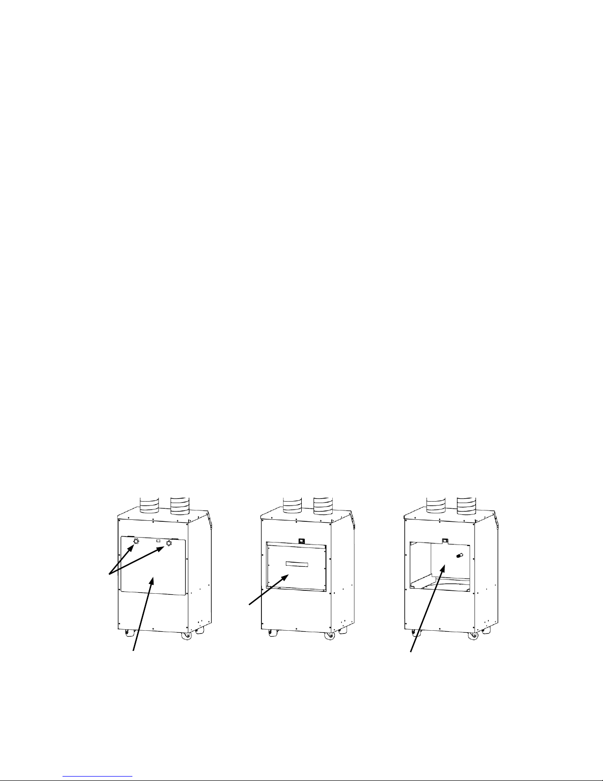
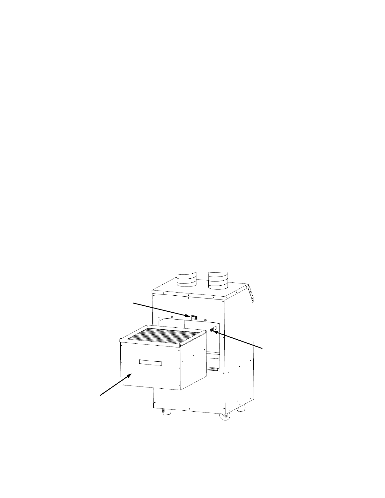
8.2.1 Turn the Power Off and unplug the Power Cord from the Power Socket.
8.2.2 Remove the Access Door by unscrewing the two (2) Thumb Screws, as
shown in shown in Fig. 7.
Fig. (7) –Access Door Removal
Thumb
Screw
Access Door
Filter
Filter Compartment
15
VIII. Filter Replacement
8.2 Filter Change
8.2.3 Remove the used Integrated Filter Module.
Caution: The HV Contact Spring may store a slight charge even after
the unit is powered off. Avoid direct contact with the HV Contact Spring.
8.2.4 Install a new Integrated Filter Module (HA-IFM-1111) into the Filter
Compartment, as shown in Fig. 8. Ensure that the plastic wrap is
removed prior to installing the replacement filter.
8.2.5 Reinstall the Access Door, ensuring that the Access Door is properly
inserted back into its track. Once the Access Door is properly aligned
and set in place, secure it by screwing in the Thumb Screws.
Note that, if the Access Door must be properly installed to engage the
Safety Switch. If the Safety Switch is not engaged, the unit will not
power on.
8.2.6 Plug the Power Cord back into the Power Socket and wall socket.
Fig. (8) –Replacement Filter Installation
Integrated Filter Module
HA-IFM-1111
HV Contact Spring
Safety Switch

16
VIII. Filter Replacement
8.3 Filter Change Indicator Light Reset
Once the filter has been replaced and the unit is powered on, the Filter Change
indicator light may continue to flash. To reset the filter change timer and
deactivate the flashing light, go through the following reset procedure:
8.3.1 Unplug the Power Cord from the Power Socket, wait a couple seconds
and plug the Power Cord back into the Power Socket.
8.3.2 Press and hold down the Power Button [ ] on the Control Panel (not
the Remote Control) for five (5) seconds.
8.3.3 After five (5) seconds, release the Power Button. The filter change
timer will reset to 400-hours, after which the Filter Change indicator
light will shut off.
Fig. (9) - Filter Change Indicator Light Reset
Filter Change
indicator light
flashing
Press and Hold
Power button for
5 seconds
17
IX. Maintenance
Caution: The HV Contact Spring may store a slight charge even after the unit
is powered off. Avoid direct contact with the HV Contact Spring.
9.1 Cleaning Filter
To extend the effective life of the Integrated Filter Module, remove the filter
from the unit and use a standard vacuum to remove collected particulate from
the Pre-Filter section.
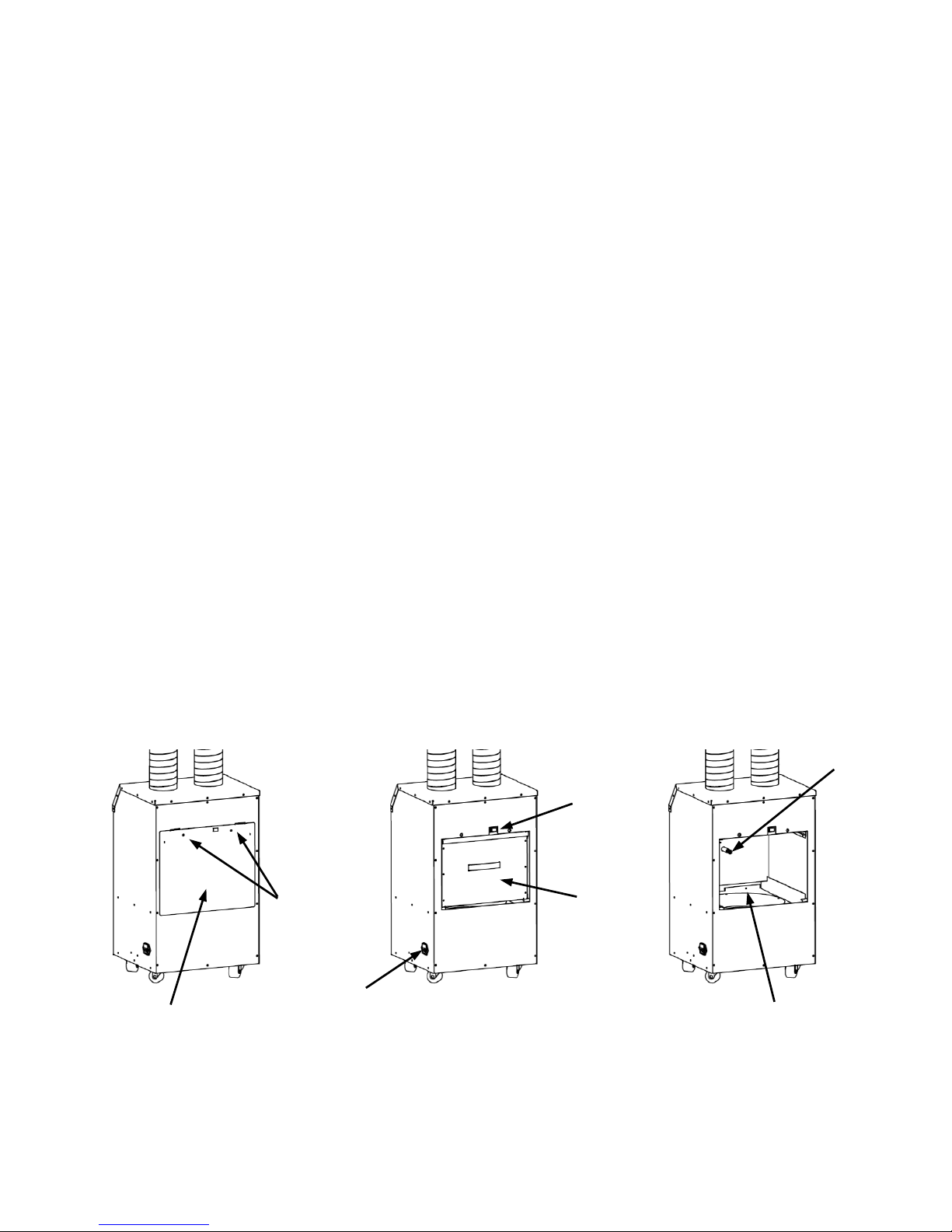
9.2 Cleaning Filter Compartment
Visually inspect the interior of the Filter Compartment when the filter is
removed from the unit during the filter replacement process. If particulate has
accumulated in the Filter Compartment, clean the interior of the unit as follows:
9.2.1 Turn the Power Off, unplug the Power Cord from the Power Socket,
remove the Access Door, and remove the filter from the unit.
9.2.2 Vacuum and remove any debris that has accumulated in the filter
compartment and adjacent accessible areas of the interior of the unit.
9.2.3 Properly replace the Access Door, as described in Section 8.2.
Fig. (10) –Cleaning Filter Compartment
Power
Socket
Thumb
Screw
Access Door
Filter
Filter Compartment
HV
Contact
Spring
Safety
Switch

18
X. Basic Service and Troubleshooting
The Basic Service Guide should cover most performance issues. If you continue
to experience issues after referring to this list, please contact Healthy Air Inc.
10.1 Air Purification System is Inoperable
If the unit fails to power on, the issue may be the result of one of the following
causes. In some cases, the unit will require service by the manufacturer or a
professionally licensed electrician.
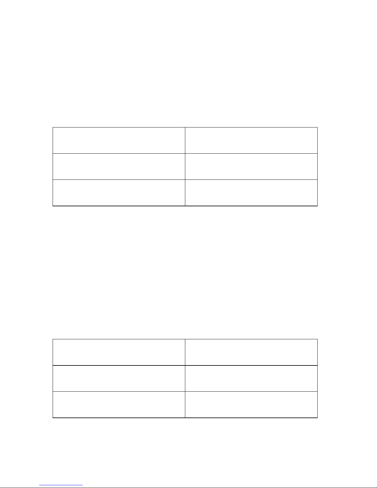
Possible Cause
Solution
Blown Fuse
Replace the Fuse
Safety Switch not engaged
Properly close the Access Door
Safety Switch malfunction
Replace the Safety Switch
HV Board malfunction
Replace the HV Board
PCB Board delay function
Unplug and re-plug Power Cord
10.2 Air Purification System Powers On but Unit is Inoperable
If the unit powers on but fails to operate properly, the issue may be the result of
a faulty electrical board and will require service by the manufacturer or a
professionally licensed electrician.
Possible Cause
Solution
PCB Board malfunction
Reconnect/Replace PCB Board
19
X. Basic Service and Troubleshooting
10.3 Air Purification System Powers On but Fan is Inoperable
If the unit powers on but the fan fails to operate, the issue may be the result of
a faulty motor and will require service by the manufacturer or a professionally
licensed electrician.
Possible Cause
Solution
Fan/Motor malfunction
Replace the Fan/Motor
PCB Board malfunction
Replace the PCB Board
10.4 Fan Speed Cycle Error
If the unit does not properly cycle through all three (3) fan speed settings, or
the unit shuts off when cycling through the fan speed settings, the issue may
be the result of one of the following causes.
Contact the manufacturer for the Control Panel reset instructions. If that does
not resolve the issue, the unit will require service by the manufacturer or a
professionally licensed electrician.
Possible Cause
Solution
Control Panel program error
Control Panel reset procedure
Display Board malfunction
Replace Display Board
This manual suits for next models
2
Table of contents


