Ekars EPT-2201A User manual

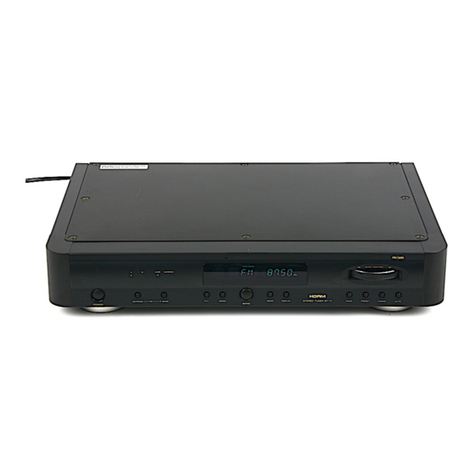
EPT-2201A
Public Address
AM/FM STEREO
Digital Tuner
OPERATING MANUAL
P. A. SYSTEM

1
Contents
1
1. Unpacking And Installation ------------------------------------------------------------------------- 2
2. Features -------------------------------------------------------------------------------------------------- 3
3. Front Panel Controls -------------------------------------------------------------------------------- 4, 5
4. Rear Panel Controls ----------------------------------------------------------------------------------- 6
5. Installation of the Antenna ---------------------------------------------------------------------------- 7
6. -------------------------------------------------- 8
7. Connections -------------------------------------------------------------------------------------------- 9
8. Specifications ------------------------------------------------------------------------------------------- 10
Home Page : http://www.ekars.co.kr
http://www.samhyoung.co.kr
SamHyoung Electronics Co., Ltd.
How to connect cable connector
65, Barangongdan-ro 5-gil, Hyangnam-eup,
Hwaseong-city, Gyeonggi-do, Korea (18623)
Tel : +82-31-432-5112 / +82-31-432-4422
Fax : +82-31-352-7649
75 coaxialΩ

Unpacking And Installation
2
Although it is neither complicated to install nor difficult to operate your Digital Tuner
a few minutes of your time is required to read manual for a properly wired installation
and becoming familiar with its many features and how to use them.
Please take a great care in unpacking your Digital Tuner and do not discard the carton
and other packing materials.
They may be needed with when moving your set and are required if it ever becomes
necessary to return your set for service.
Never place the unit radiators, in front of heating vents, in excessively humid or dusty
location to avoid early damage and for your years of quality use.
Connect your complementary components as illustrated in the following page.
The instruction for use shall state that the apparatus shall not be exposed to dripping or
splashing and that no objects filled with liquids, such as vases, shall be placed on the
Apparatus.
CAUTION
:
TO REDUCE THE RISK OF ELECTRIC SHOCK.
DO NOT REMOVE COVER (OR BACK).
NO USER-SERVICEABLE PARTS INSIDE.
REFER SERVICING TO QUALIFIED
SERVICICE PERSONNEL.
WARNING:
TO PREVENT FIRE OR SHOCK HAZARD,
DO NOT EXPOSE THE UNIT TO RAIN OR
MOISTURE.
This symbol is intended to alert the user to the
presence of uninsulted "dangerous voltage"
with in the product's enclosure that may be of
sufficient magnitude to constitute a risk of
electric shock to persons.
This symbol is intended to alert the user to the
presence of important operation and maintenance
(servicing) instructions in the literature
accompanying the appliance.
To prevent electric shock do not use this
(polarized) plug with an extension cord,
receptacle or other outlet unless the blades can
be fully inserted to prevent blade exposure.
CAUTION :

This unit is provided 1 STEREO XLR output.
This tuner is able to the memory twenty-four broadcasting frequencies of each AM/FM.
STEREO XLR OUTPUT
24 FREQUENCY MEMORIES
6+6+6 FM Presets.
6 AM Presets.
Retains Presets When Power is off.
Large LCD Digital Display.
Scan and Seek Functions.
Auto Store Memory Functions (A/PS).
DC 24V Operation.
Standard 1 Space EIA Rack Chassis.

1. POWER SWITCH
2. FREQUENCY DISPLAY
3. BAND BUTTON
4. TUNE UP/DOWN BUTTON
TUNE UP :
TUNE DN :
Pushing this switch shortly, Unit is turned on and operated.
Pushing this switch more than 2sec, Unit is turned off and is become the stand-by state.
cf. Even if you press any switch, this unit is turned on and operated.
You can confirm the frequency of tuner through this display
Whenever press this switch, Radio bands are converted by order of
FM1 FM2 FM3 MW.
Push the button 1time, move to next broadcasting frequency.
Pushing the button for 1sec, move to next frequency continuously for pushing the button.
Push the button 1time, move previous broadcasting frequency.
Pushing the button for 1sec, move previous frequency continuously for pushing the button.
→→→
23 4 6
17
5

5
Front Panel Controls
5. MEMO 1~ MEMO 6 SELECTION BUTTON
How to memory :
6. STAND-BY INDICATOR
7. GAIN CONTROL VOLUME
This is PRESET switch to select pre-memorizes broadcasting channel on each switch.
You can memory broadcasting channel which you want to listen, in each switch (1~6).
Totally 24 channels (FM1 : 6Ch, FM2 : 6Ch, FM3 : 6Ch, MW1 : 6Ch) can be memorized.
Use TUNE UP, TUNE DN switch to select broadcasting channels and push one switch
from 1~6, for a long time(more than 1 sec) to memory selected broadcasting channel.
You can memory other broadcasting channels on the rest 5 switches in the same way.
This LED is the operating stand-by indicator of the this unit.
This is always lighted regardless with the ON / OFF state of the power switch of this unit.
This volume adjusts the gain of the output of this Unit.
If turn this volume clockwise, sound level is increased and
if turn this knob counter-clockwise, sound level is decreased.
▪
23 4 6
17
5

6
1. ANTENNA TERMINAL
2. DC INPUT TERMINAL
3. STEREO OUTPUT JACK
This terminal is for connecting the antennal.
In the regions where FM broadcasting signal is poor, kindly install the outdoor antenna.
This is the DC INPUT terminal for the DC 24V Input.
This jack is the stereo output jack of this unit.
This is for connection to the TUNER INPUT jack of Pre Amplifier.
Rear Panel Controls

7
Installation of the Antenna
INDOOR ANTENNA
In the regions where FM broadcasting is heard comparatively well due to the
near distance to the station or wooden structure, you can receive
broadcasting of good quality by using a lead wire antenna.
INSTALLATION OF ANTENNA USING THE COAXIAL CABLE
Noisy reception may occur in built-up areas and factory sites as well as
around power cables. This may be the case even when an antenna is used
exclusively for FM.
In these regions, install the antenna using 75 coaxial cable.
Listening to the broadcasting, fix the antenna after deciding the location and
the direction so that the reception may be optimized.
After connecting the 75 coaxial cable using the 75 coaxial cable connector,
Please connect to the antenna input terminal of this unit.
Ω
ΩΩ
75 COAXIAL
CABLE
Ω
75 coaxial cable
Connector
Ω
EPT-2201A
Rear Panel
Lead wire
Antenna
Indoor Antenna
Outdoor Antenna

8
How to connect cable connector75 coaxialΩ
No.
7
8
9
75Ωcoaxial cable and connector should be work in the following order.
2Prepare the supplied antenna connector.
3Disassemble the antenna connector.
4Insert the coaxial cable
into the right-side PVC cover.
5Adhere the shield line of the coaxial
cable to the body.
6Make sure fixed with screws
so as not to move the core wire.
fix the left side PVC cover
on the groove of the body.
After moving right-side PVC cover
to the left, secure it by turning to the right.
When the assembly is completed,
connect to the antenna input terminal.
1
Make cut the other end of the coax cable
connected to the outdoor antenna
as shown in figure.

9
Connections
DIGITAL TUNER
EPT-2201A
DIGITAL TUNER
EPT-2201A

10
Antenna Input --------------------------------------------------------------- 75 ohms (Unbalanced)
Output Level (Stereo L, R Output) -------------------------------------------- 0.245V (-10 dBm)
--------------------
--------------------------------------------------------------------------
FM
Tuning Range ----------------------------------------------------------------- 87.5 MHz ~ 108 MHz
Useable Sensitivity -------------------------------------------------------------------------------- 6 dB
Signal to Noise Ratio ---------------------------------------------------------------------------- 60 dB
AM
Tuning Range ------------------------------------------------------------------ 522 kHz ~ 1,620 kHz
Useable Sensitivity ------------------------------------------------------------------------------- 34 dB
Signal to Noise Ratio ---------------------------------------------------------------------------- 40 dB
Power Requirements ---------------------- ----------------- 24 Vdc, 0.25 Amax
Power Consumption 6 Watts
Net Weight (kg / lb) -------------------------------------------------------------------------- 2.0 / 4.4
Dimensions -------------------------------------------------------- 483(W) x 44(H) x 200(D) mm
19.01(W) × 1.74(H) ×7.9(D) inch

MEMO
36, ro 198beon-gil, Wonmi-gu,
Bucheon-city , Korea (14557)
Tel : +82-2-2612-4422
Fax : +82-2-2612-7676
Bucheon-
Gyeonggi-do
Bucheon office
65, Barangongdan-ro 5-gil, Hyangnam-eup,
Hwaseong-city, Gyeonggi-do, Korea (18623)
Tel : +82-31-432-5112 / +82-31-432-4422
Fax : +82-31-352-7649
Home Page : http://www.ekars.co.kr / http://www.samhyoung.co.kr
Headquarter & Overseas Dep.
Table of contents
