Marantz ST-17 User manual

ENGLISHFRANÇAIS
Model ST-17 User Guide
Stereo Tuner
R

1
ENGLISH FRANÇAIS
CAUTION
RISK OF ELECTRIC SHOCK
DO NOT OPEN
CAUTION: TO REDUCE THE RISK OF ELECTRIC SHOCK,
DO NOT REMOVE COVER (OR BACK)
NO USER-SERVICEABLE PARTS INSIDE
REFER SERVICING TO QUALIFIED SERVICE PERSONNEL
The lightning flash with arrowhead symbol, within
an equilateral triangle, is intended to alert the user
to the presence of uninsulated “dangerous voltage”
within the product’s enclosure that may be of suffi-
cient magnitude to constitute a risk of electric shock
to persons.
The exclamation point within an equilateral triangle
is intended to alert the user to the presence of
important operating and maintenance (servicing)
instructions in the literature accompanying the
appliance.
WARNING
TO REDUCE THE RISK OF FIRE OR ELECTRIC SHOCK,
DO NOT EXPOSE THIS APPLIANCE TO RAIN OR MOISTURE.
CAUTION:
TO PREVENT ELECTRIC SHOCK, MATCH WIDE BLADE
OF PLUG TO WIDE SLOT, FULLY INSERT.
ATTENTION: POUR ÉVITER LES CHOCS ÉLECTRIQUES,
INTRODUIRE LA LAME LA PLUS LARGE DE LA FICHE DANS LA
BORNE CORRESPONDANTE DE LA PRISE ET POUSSER
JUSQU’AU FOND.
NOTE TO CATV SYSTEM INSTALLER:
This reminder is provided to call the CATV (Cable-TV) system installer’s attention to Article 820 – 40 of the NEC, that
provides guidelines for proper grounding and, in particular, specified that the cable ground shall be connected to the
grounding system of the building, as close to the point of cable entry as practical.
NOTE:
This equipment has been tested and found to comply
with the limits for a Class B digital device, pursuant to
Part 15 of the FCC Rules. These limits are designed to
provide reasonable protection against harmful interfer-
ence in a residential installation. This equipment gener-
ates, uses and can radiate radio frequency energy and, if
not installed and used in accordance with the instruc-
tions, may cause harmful interference to radio commu-
nications. However, there is no guarantee that interfer-
ence will not occur in a particular installation. If this
equipment does cause harmful interference to radio or
television reception, which can be determined by tuning
the equipment off and on, the user is encouraged to try
to correct the interference by one or more of the follow-
ing measures:
– Reorient or relocate the receiving antenna.
– Increase the separation between the equipment and
receiver.
– Connect the equipment into an outlet on a circuit
different from that to which the receiver is connected.
– Consult the dealer or an experienced radio/TV techni-
cian for help.
NOTE:
Changes or modifications may cause this unit to fail to
comply with Part 15 of the FCC Rules and may void the
user's authority to operate the equipment.

1
This product was designed and manufactured to meet strict quality and
safety standards. There are, however, some installation and operation
precautions which you should be particularly aware of.
1. Read Instructions – All the safety and operating instructions should
be read before the appliance is operated.
2. Retain Instructions – The safety and operating instructions should
be retained for future reference.
3. Heed Warnings – All warnings on the appliance and in the
operating instructions should be adhered to.
4. Follow Instructions – All operating and use instructions should be
followed.
5. Water and Moisture – The appliance should not be used near
water – for example, near a bathtub, wash-bowl, kitchen sink,
laundry tub, in a wet basement, or near a swimming pool, etc.
6. Carts and Stands – The appliance should be used only with a cart
or stand that is recommended by the manufacturer.
7. An appliance and cart combination should be moved with care.
Quick stops, excessive force, and uneven surfaces may cause the
appliance and cart combination to overturn.
8. Wall or Ceiling Mounting – The appliance should be mounted to a
wall or ceiling only as recommended by the manufacturer.
9. Ventilation – The appliance should be situated so that its location
or position does not interfere with its proper ventilation. For
example, the appliance should not be situated on a bed, sofa, rug,
or similar surface that may block the ventilation openings; or,
placed in a built-in installation, such as a bookcase or cabinet that
may impede the flow of air through the ventilation openings.
10. Heat – The appliance should be situated away from heat sources
such as radiators, heat registers, stoves, or other appliances
(including amplifiers) that produce heat.
11. Power Sources – The appliance should be connected to a power
supply only of the type described in the operating instructions or as
marked on the appliance.
12. Grounding or Polarization – Precautions should be taken so that
the grounding or polarization means of an appliance is not
defeated.
AC POLARIZED PLUG
13.
Power-Cord Protection – Power-supply cords should be routed so
that they are not likely to be walked on or pinched by items placed
upon or against them, paying particular attention to cords at plugs,
convenience receptacles, and the point where they exit from the
appliance.
14. Cleaning – The appliance should be cleaned only as recom-
mended by the manufacturer.
15. Power Lines – An outdoor antenna should be located away from
power lines.
16. Outdoor Antenna Grounding – If an outside antenna is connected
to the receiver, be sure the antenna system is grounded so as to
provide some protection against voltage surges and built up static
charges.
Section 810 of the National Electrical Code, ANSI/NFPA No. 70-
1984, provides information with respect to proper grounding of the
mast and supporting structure, grounding of the lead-in wire to an
antenna discharge unit, size of grounding conductors, location of
antenna-discharge unit, connection to grounding electrodes, and
requirements for the grounding electrode. See Figure 1.
17. Nonuse Periods – The power cord of the appliance should be
unplugged from the outlet when left unused for a long period of
time.
18. Object and Liquid Entry – Care should be taken so that objects do
not fall and liquids are not spilled into the enclosure through
openings.
19. Damage Requiring Service – The appliance should be serviced by
qualified service personnel when:
A. The power-supply cord or the plug has been damaged; or
B. Objects have fallen, or liquid has spilled into the appliance; or
C. The appliance has been exposed to rain; or
D. The appliance does not appear to operate normally or exhibits
a marked change in performance; or
E. The appliance has been dropped, or the enclosure damaged.
20. Servicing – The user should not attempt to service the appliance
beyond that described in the operating instructions. All other
servicing should be referred to qualified service personnel.
SAFETY
INSTRUCTIONS
READ BEFORE OPERATING EQUIPMENT

2
ENGLISH FRANÇAIS
FIGURE 1
EXAMPLE OF ANTENNA GROUNDING ACCORDING TO
NATIONAL ELECTRICAL CODE INSTRUCTIONS
CONTAINED IN ARTICLE 810 - “RADIO AND TELEVISION EQUIPMENT”
NOTE TO CATV SYSTEM INSTALLER:
This reminder is provided to call the CATV (Cable-TV) system installer’s attention to Article 820 – 40 of the NEC, which provides
guidelines for proper grounding and, in particular, specifies that the cable ground shall be connected to the grounding system of
the building, as close to the point of cable entry as practical.
GROUND CLAMPS
POWER SERVICE GROUNDING
ELECTRODE SYSTEM
(NEC ART 250, PART H)
ANTENNA
DISCHARGE UNIT
(NEC SECTION 810–20)
GROUNDING CONDUCTORS
(NEC SECTION 810–21)
ANTENNA
LEAD IN
WIRE
GROUND
CLAMP
ELECTRIC
SERVICE
EQUIPMENT
NEC –NATIONAL ELECTRICAL CODE

3
ENGLISHFRANÇAIS
STEREO TUNER ST-17
A B
WIDE NARROW
BAND
MEMO
MONOIF BANDFM
ANTENNA
POWER
DISPLAY ST NAME PRESET TUNING AUTO
kHz
MHz
PRESET
MEMORY
AUTO TUNING
TUNED
MUTING
STEREO
MONO
kHz
MHz
PRESET
MEMORY
AUTO TUNING
TUNED
STEREO
MONO
rw t u o !0 !1 !2iy
q!4
å∫ ∂ é ƒ
©˙ !3
e
ç
R
L
R
IN
OUT
REMOTE
CONTROL
OUTPUTAM ANTENNAFM ANTENNA BFM ANTENNA A
75Ω75ΩGND AM
LOCAL
DX
FM ATT.
FM DE-EMPHASIS
AM SCAN STEP
9 kHz 10 kHz
50 µS75µS
220V110V
D FE
A B GC
Figure 1
Figure 2

4
ENGLISH FRANÇAIS
INTRODUCTION
Thank you for selecting the Marantz model ST-17 Stereo Tuner
for your audio system. This Stereo Tuner incorporates a number
of features designed to enhance the listening of your favorite
audio sources.
Please read these operating instructions carefully. We
recommend that you read the entire user guide before you
attempt to connect or operate the unit.
After you have reviewed the contents of this manual, we suggest
that you make all system connections before you attempt to
operate the unit.
Refer to the Figures on pages 3 and 20 at the rear of this user
guide.
The callout numbers on the Figures correspond to those found in
the text. All references to the connections and controls that are
printed in BOLD type are as they appear on the unit.
PRECAUTIONS
The following precautions should be taken when operating the
equipment.
GENERAL PRECAUTIONS
When siting the equipment ensure that:
— the ventilation holes are not covered;
— air is allowed to circulate freely around the equipment
— it is on a vibration free-surface;
— it will not be exposed to interference from an external source;
— it will not be exposed to excessive heat, cold, moisture or
dust;
— it will not be exposed to direct sunlight;
— it will not be exposed to electrostatic discharges
Never place heavy objects on the equipment.
If a foreign body or water dose enter the equipment, contact
your nearest dealer or service center.
Do not pull out the plug by pulling on the mains lead, hold the
plug.
It is advisable when leaving the house, or during a
thunderstorm, to disconnect the equipment from the mains
supply.
EQUIPMENT REAR PANEL
CONNECTIONS AND CONTROLS
(Figure 1)
ABC ANTENNA CONNECTIONS
Both FM and AM antenna can be connected to the tuner's terminals.
AFM ANTENNA TERMINAL
The FM ANTENNA terminal is used to connect an external FM antenna
with a circular plug. It can also be used to connect the accessory FM
feeder antenna.
BFM ANTENNA B TERMINAL
The FM ANTENNA terminal is used to connect an external FM antenna
with a circular plug, or for connecting a cable network to the tuner.
CAM ANTENNA TERMINAL
The AM terminal and the GND terminal are used to connect the high-
performance, low-impedance, AM loop antenna that is provided with the
receiver. The AM loop antenna can be used on top of the tuner or can
be mounted on a suitable rack or shelf near the tuner. Interference may
be reduced if the tuner is earthed.
In areas where the AM loop antenna supplied gives unsatisfactory
result, it is recommended that the tuner be connected to an outdoor
antenna. Use the terminal marked AM for this. Anearthing lead can be
connected to the terminal marked GND to further reduce interference.
DFM ATTENUATE SWITCH (FM ATT.)
This switch attenuates the FM signal input to the ATTENNA B terminal.
DX : For use when the FM signal is comparatively weak.
(The input FM signal is not attenuated.)
LOCAL: For use when the FM signal is comparatively strong.
(The input FM signal is attenuated by approx. 20dB.)
EOUTPUT JACKS
With the lead supplied, connect the output jacks to the tuner inputs of
your amplifier.
FREMOTE CONTROL BUS TERMINALS
Another item of audio equipment with a remove control bus terminal can
be connected to these terminals by using a specialpurpose cable. The
bus OUT terminal is used to send signals to another item of equipment.
The bus IN terminal is used to receive signals from another item of
equipment.
GAC POWER CONNECTION
The correct voltage for operating your tuner is indicated on the rear
panel. Be sure the POWER switch is off before plugging the AC mains
lead into an electrical outlet.
HSCAN-STEP SELECTION
Changes the step when the tuner searches for the next station up or
down the scale. In Europe this swich should be set to 9 kHz steps in
AM.
IFM DE-EMPHASIS SWITCH
This models are equipped with switchable de-emphasis.
The de-emphasis switch works in conjuction with this scan-step selector
switch.
The de-emphasis set to 50˚s when delivered from the factory.
CAUTION
THE UNIT MUST BE TURNED OFF BEFORE CHANGING
THE SCAN-STEP SELECTOR SWITCH POSITION.
WHEN THIS SWITCH IS SET TO OFF, THE CONTENTS OF
THE PRESET MEMORY AND STATION NAME ARE
ERASED AT THAT TIME, STORE THE CONTENTS AGAIN.

5
ENGLISHFRANÇAIS
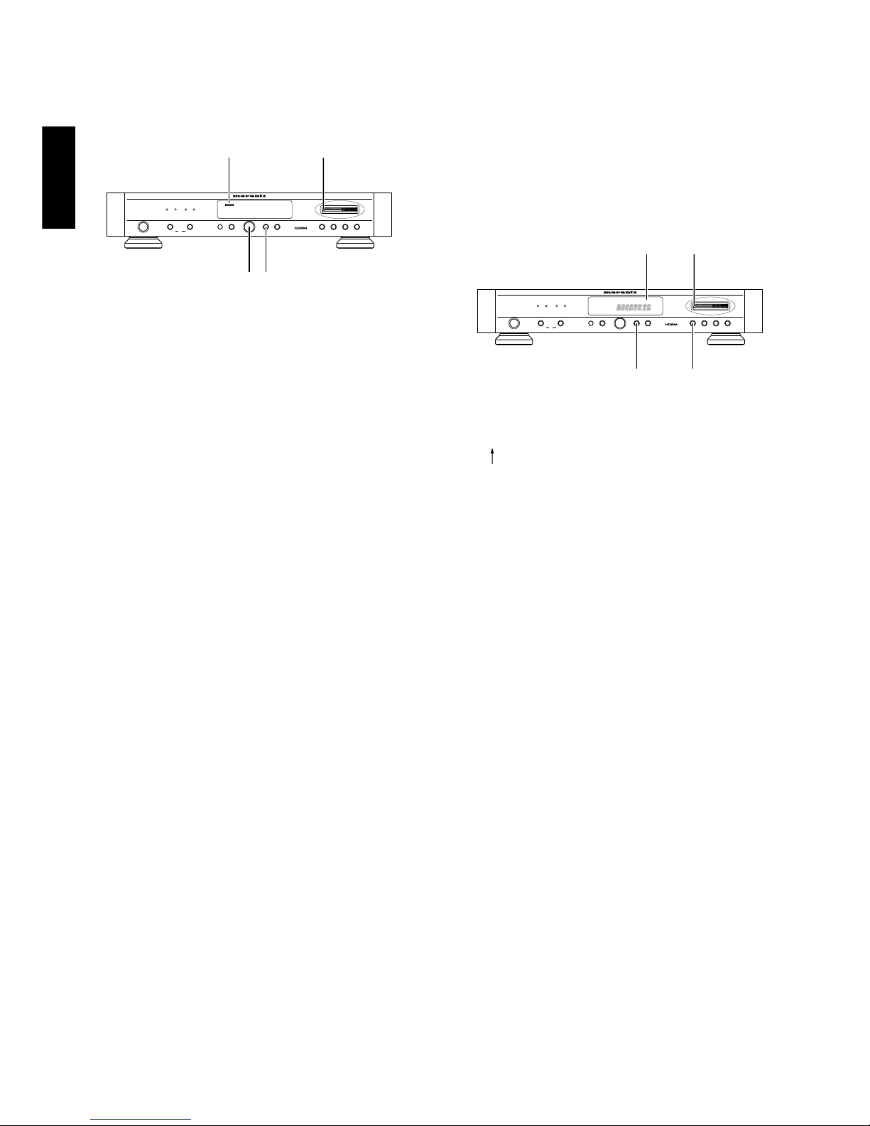
EQUIPMENT FRONT PANEL
CONNECTIONS AND CONTROLS
(Figure 2)
qPOWER SWITCH
Press to switch the power ON. Press again to switch to power OFF.
The mains switch is secondary connected and does not disconnect the
entire set from the mains.
wANTENNA BUTTON
This button is only operable when the FM band is selected.
This button selects FM ANTENNA A and FM ANTENNA B.
The selected side’s LED will light.
eIF BAND BUTTON
This button is only operable when the FM band is selected.
This button selects the IF band’s WIDE or NARROW setting.
The selected side’s LED will light.
WIDE: High quality audio can be listened to.
NARROW: Ability to select neighboring stations is improved.
rIR SENSOR
Receives the infrared remote control signal.
tMONO BUTTON
Press to switch the receiving mode between the auto stereo mode and
more mode.
When the button is pressed into the in position, the receiving mode
becomes the mono mode.
When the button is pressed again, the receiving mode becomes the
auto stereo mode.
yBAND BUTTON
Use this button to select FM or AM wave bands.
uMEMO BUTTON
Press to preset a receiving frequency in the memory. The MEMORY
indicator lights up for about 5 seconds when this button is pressed. It is
only during this period that a frequency can be preset in the memory.
iDISPLAY BUTTON
When this button is pressed while a station name is being displayed, the
display is switched to the frequency display.
Pressing the button again returns to the station name display; if no
station name has been stored for the station being received. “NO
NAME” is displayed when the button is pressed.
oST-NAME BUTTON
Press before manual input of station name.
For details, refer to “NANUAL INPUT OF STATION NAMES”.
!0 PRESET BUTTON
For switching the GYRO CONTROL ring to the preset mode.
!1 TUNING BUTTON
For switching the GYRO CONTROL ring to the tuning mode.
!2 AUTO BUTTON
For switching the GYRO CONTROL ring to the auto tuning mode.
!3 GYRO CONTROL RING
Used for dialing control of tuning up/down, preset up/down, station
name character display and PTY selection.
!4 DISPLAY
åMEMORY – This indicator lights up for about 5 seconds after the
MEMO button has been pressed.
∫PRESET – This indicator lights up when the PRESET button is
pressed.
çSTEREO – This indicator lights up when an FM stereo broadcast is
being received.
∂AUTO TUNING – This indicator lights up when the AUTO TUNING
mode.
éTUNING – This indicator lights up when the MANUAL TUNING
mode.
ƒTUNED – This indicator lights up when a station is tuned.
©FREQUENCY/STATION NAME – This indicator shows frequencies in
MHz (FM) or kHz (AM), (RDS) station name, radio text or names you
have assigned.
˙MONO – This indicator lights up in the MONO mode, which is
initiated when the MONO button is pressed.
OPERATION ON THE MAIN UNIT
SWITCHING ON AND OFF
When you want to switch you tuner on, press the POWER button.
When you wish to switch the unit off, simply press the POWER button
again.
SELECTING THE WAVE BAND
Select the desired wave band (FM, AM) by pressing the BAND
button. Pressing this button switches to the next wave band in the
following order: FM - AM - FM.
The display shows the selected band.
AUTO TUNING
This method can be used in areas where the signal strengths of the
broadcast atations are normal.
1. Confirm that the “AUTO” and “TUNING” indicators are lit on the
display. If not lit, turn the indicators on by pressing the TUNING
button and AUTO button.
2. Gently move the GYRO CONTROL ring.
The received frequency will automatically change and tuning will stop
when a station is received.
3. Repeat moving the GYRO CONTROL ring gently until the desired
station is received.
NOTE:
While the GYRO CONTROL ring is being turned, even if a station is
tuned in, it will not be stopped at.
MANUAL TUNING
This method can be used in areas where the signal strengths of the
broadcast atations are normal.
1. Confirm that the “TUNING” indicator is lit on the display. If not lit, turn
the indicator on by pressing the TUNING button.
2. If “AUTO” is lit on the display, press the AUTO button to turn it off.
3. Turn the GYRO CONTROL ring until the frequency you want is
received. The speed of received frequency display corresponds to
the speed that you turn the ring. Also, received frequencies will
change at 100kHz steps for FM and 9kHz steps for AM.
PRESET TUNING
Use the following procedure to recall a preset station directory from the
preset memory.
1. Ensure that the PRESET indicator is lit in the display. If nor, press the
PRESET button to light it..
2. Rotate the GYRO CONTROL ring to select the desired preset station.
PRESET MEMORY ON THE MAIN UNIT
This unit is equipped with the one-touch preset tuning system which is
particularly convenient when there is a large number of receivable
stations. The preset tuning system allows up to 60 stations on FM and
AM to be preset in a random order.

6
ENGLISH FRANÇAIS
HOW TO PRESET A FREQUENCY IN THE MEMORY
1. Select FM or AM with the BAND button.
2. Select the desired station with the GYRO CONTROL ring.
3. Press the MEMO button.
“MEMORY” will flash on the display.
4. While the “MEMORY” indicator is flashing (approx. 5 sec.), turn the
GYRO CONTROL ring to the left or right to select the desired preset
number.
5. Press the MEMO button again.
The “MEMORY” indicator will go out, and memorization will be
finished.
CALLING UP STORED STATIONS
1. Confirm that the “PRESET” indicator is lit on the display. If not lit,
press the PRESET button to turn it on.
2. Turn the GYRO CONTROL ring to select the desired preset station.
DELETING THE CONTENTS OF THE PRESET MEMORY
1. Select the preset station you wish to delete.
2. Press the MEMO button.
The “MEMORY” indicator will flash on the display.
3. While the “MEMORY” indicator is flashing (approx. 5 sec.), turn the
GYRO CONTROL ring to set the preset number to “00”.
4. Press the MEMO button again.
The preset number and the “CLEAR” indicator will flash for approx. 2
seconds on the display and the memory will be deleted.
Station names memorized for the preset station will also be deleted at
the same time.
<GYRO RING operation method>
When the GYRO ring is turned to the right, the frequency or preset
number will increase, and when turned to the left, they will decrease.
STEREO TUNER ST-17
A B
WIDE NARROW
BAND
MEMO
MONOIF BANDFM
ANTENNA
POWER
DISPLAY ST NAME PRESET TUNING AUTO
MEMORY
4
1
2, 4
3, 5
1. Select and display the preset channel you wish to register.
2. Press the ST NAME button.
The display’s frequency indicator will go out, “MEMORY” will flash
and “_ _ _ _ _ _ _ _” will appear.
INPUT OF STATION NAMES ON THE
MAIN UNIT
The display automatically shows the name of an RDS station when it is
being received.
It is also possible to have the station name of a non-RDS station
displayed by entering the station name manually.
HOW TO INPUT A STATION NAMES
STEREO TUNER ST-17
A B
WIDE NARROW
BAND
MEMO
MONOIF BANDFM
ANTENNA
POWER
DISPLAY ST NAME PRESET TUNING AUTO
1
5
3
2, 4
* When a station other than a preset station is selected, and the CHAR.
button is pressed, the frequency indicator will remain lit, the
“PRESET” indicator will flash and the station name can not be
registered.
3. Use the GYRO CONTROL ring to input the desired number or letter at
the first flashing digit on the left side.
When the GYRO CONTROL ring is turned to the right, input will
change in the following order: A – Z_ . . 0 – 9 A –.
When turned to the left, input will change in the following order: 9 – 0
. . _ Z – A 9 –. (“_” indicates a space.)
4. Press the ST NAME button when the first digit on the left has been
input.
Flashing will move to the second digit. Input the desired number or
letter using the same procedure as in step 3, and press the CHAR.
button.
Repeat this procedure to input up to 8 characters.
(The flashing position will move each time the ST NAME button is
pressed.)
5. When the desired station name has been input, press the MEMO
button.
Flashing will stop and registration will be finished.
* Although station names of up to 8 characters can be input, even if a
station name that is under 8 characters is input, pressing the MEM0
button will finish registration at that point.
CHANGING STATION NAME
To change registered station names, carry out steps 2 to 5 of the
registration procedure. The old station name will be replaced with the
new one.
TO ERASE STATION NAMES
1. Display the station name to be erased.
2. Input spaces ( _ ) at all 8 digits.
3. Press the MEMO button. The station name will be erased, and the
frequency display will be returned to.
Blinking

7
ENGLISHFRANÇAIS
BUTONNS AND OPERATION OF THE
REMOTE CONTROL UNIT
BAND
DISPLAY
MONO
MEMO
TUNING PRESET
RC-17ST
123
456
789
0
BAND
button
MONO
button Number
buttons
TUNING
UP/DOWN
buttons
MEMO
button
DISPLAY
button
PRESET
UP/DOWN
buttons
TUNING UP () / DOWN () BUTTON
Every time the UP or DOWN side of the TUNING button is pressed, the
receiving frequency varies in the upward or downward direction, in the
steps of 50 kHz in FM band or 9 kHz in AM band.
When the button is held depressed for more than 0.5 seconds, the
receiving frequency varies continuously in the above-mentioned steps
until a station is received. Press or hold the button until the desired
frequency is displayed on the digital frequency indicator.
PRESET UP () / DOWN () BUTTON
Every time the UP or DOWN side of the PRESET button is pressed, the
preset number will advanced one step in the upward or downward
direction. The unused preset numbers without memory contents are
skipped.
This button is also used as the CURSOR button in the station name
input mode.
PRESET MEMORY ON THE REMOTE CONTROL UNIT
This unit is equipped with the one-touch preset tuning system which is
particularly convenient when there is a large number of receivable
stations. The preset tuning system allows up to 60 stations on FM and
AM to be preset in a random order.
HOW TO PRESET A FREQUENCY IN THE MEMORY
1. Press the BAND button to select the desired band (FM/AM).
2. Press the TUNING UP/DOWN button to select the frequency of
desired station.
3. When th desired station is received, press the MEMO button.
4. The MEMORY indicator blinks for about 5 seconds. Press the
PRESET button within this time.
5. Example: To preset under preset no.15
Preset tuning by recalling a preset station
Select the preset no. of the desired station in the same manner as
when presetting a station in the memory.
DELETING THE CONTENTS OF THE PRESET MEMORY
1. Select the preset station you wish to delete.
2. Press the MEMO button.
The “MEMORY”indicator will flash on the display.
3. While the “MEMORY”indicator is flashing (approx. 5 sec.), turn the
GYRO CONTROL ring to set the present number to “00”.
4. Press the MEMO button again.
The preset number and “CLEAR”indicator will flash for approx. 2
seconds on the display and the memory will be deleted.
Station names memorized for the preset station will also be deleted at
the same time.
MEMO
Press Press Press within 1.5 sec.
PRESET PRESET
1 5
Example: To preset under preset no. 3.
MEMO
Press Press Leave for 1.5 sec.
PRESETPRESET
3

8
ENGLISH FRANÇAIS
MANUAL INPUT OF STATION NAMES
ON THE REMOTE CONTROL UNIT
1. Receive a preset channnel with preset tuning or using the PRESET
UP or DOWN button.
2. Press the ST NAME button of the main unit. The frequency display
disappears and changes to “_ _ _ _ _ _ _ _ ”, where the rightmost
cursor is blinking.
Blinking
* When this button is presed while a non-preset station is received,
the frequency display remains the same, “PRESET”and “”
blink, and the station name cannot be input.
3. In the leftmost column with the blinking cursor, input an alphanumeric
character using the numeric buttons.
Each press of each numeric button changes the displayed character
as shown below.
Button 1 ABC1A
Button 2 DEF2D
Button 3 GHI3G
Button 4 JKL4J
Button 5 MNO5N
Button 6 PQR6P
Button 7 STU7S
Button 8 VWX9V
Button 9 YZ( _ )Y
Button 0 +C1
4. After setting the leftmost column, press the PRESET UP button.
The blinking column moves to the right.
In the same way as 3 above, input the desired alphanumeric
character and press the PRESET UP button again.
Input other characters up to the rightmost colu,m by repeating the
above. (The blinking column can be moved to the left by pressing the
PRESET DOWN button.)
5. After the desired station name has been input, press the MEMO
button.
The blinking of the rightmost cursor stops and the input operation is
completed.
* The station name can be input with up to 5 characters, but it can
be ended with less the 5 characters by pressing the button at any
desired time.
* To correct a station name which has been entered previously,
repeat steps from 2 to 5. The previous station name can be
replaced with the new name.
* To clear a station name which has been entered previously, input
space (_) in all of the 5 columns.
Use of the remote control unit
1. Remove control unit
Use the remote control unit at a distance of less than about 5 meters
from the main unit.
To ensure remote control operation, do not point the remote control unit
to other direction that the IR sensor of the main unit and remove
obstacles between the remote control unit and IR sensor. Operation
may also become impossible when strong light is incident to the IR
sensor.
2. Operation range of the remote control unit
FM/AM
DISPLAY
MONO
MEMO
TUNING PRESET
RC-17ST
123
456
789
0
STEREOTUNERST-17
AB
WIDENARROW
BAND
MEMO
MONO
IFBAND
FM
ANTENNA
POWER
DISPLAY STNAMEPRESET TUNINGAUTO
60˚
Approx. 5m
Remote control unit (RC-17ST)
3. Loading battery
qTurn the remote control unit upside down and side open the battery
case in the direction of using a sharp such as the tip of a ball-
point pen.
wLoad the battery case with the provided battery, insert the battery
correctly according to the “”indication on the battery case then
slide the battery case into the remote control unit it clicks.
Battery case
Battery (CR2025)
Insert the battery with the
positive ()side facing up.
Tuner (ST-17)

9
ENGLISHFRANÇAIS
The battery life is about 1 year under normal use.
The life is depended on the operating condition. Take the battery out of
the unit when it is not to be used for a long period of time.
Keep the battery out of reach of children.
If it is swallowed, immediately call the doctor.
Improper use of battery may lead to fluid leakage or battery
explosopn. Use special care in the following points when
handling a battery.
Insert the battery with correct position and negative polarity as
indicated on the equipment.
A used battery should be disposed of in the battery disposal
box installed in your dealer.
Caution on battery
Additional description on remote control bus terminal
If it is required to connect this unit to other MARANTZ equipment
equipped with REMOTE CONTROL terminals and control both pieces of
equipment as a system, change the remote control signal which can
operate this unit to the signal from the REMOTE CONTROL input
terminal by performing the following procedure before connecting this
unit with other equipment.
Without this procedure, the system control of this unit is impossible even
when it is connected through the REMOTE CONTROL terminal.
The following procedure is not required if the system connection
through the REMOTE CONTROL terminal is not used.
1. Set the POWER switch to the off position and, while holding the
BAND and DISPLAY buttons simultaneously, press the POWER
switch to ON.
2. “”blinks for 2 seconds on the display, indicating that the
remote control of this unit will thereafter be based on the external
signal input through the REMOTE CONTROL terminal. In this case,
the IR sensor of the main unit will no longer accept the signals from
the remote control unit. The remote control unit should be pointed to
the IR sensor of the equipment connected to this unit.
* To return to the initial condition, perform the same operation as
step 1 above. “”blinks for 2 seconds on the display and
the remote control condition returns to the initial condition.
SYSTEM REMOTE CONTROL UNIT
When the ST-17 is connected with the PM-17 through a system control
cord, the ST-17 can be controlled as a part of system using the RC-
17PM system remote control unit provided with the PM-17.
CONTROLS OF THE SYSTEM REMOTE CONTROL UNIT
(RC-17PM)
123
654
78
0
9
REPEAT PHONO
TAPE 1
TAPE 2
LINE 1 /TUNER
LINE 2 /TV
LINE 3 /DVD
CD
RANDOM
+/A
-/B
VOLUME
OPEN
/CLOSE
Number
buttons
TUNING
UP
button
TUNING
DOWN
button
BAND
button
PRESET
UP/DOWN
buttons
Press the LINE 1/TUNER button to switch the input selector of the PM-
17.
BAND BUTTON (LINE 1/TUNER)
Use this button to select FM or AM wave bands.
NUMERIC BUTTONS (0 to 9)
Use these buttons to preset receiving frequencies in the memory or to
recall the preset frequencies from the memory (Preset tuning).
Up tp 30 stations in the FM and AM bands can be preset in the memory
in a random order.
For operation of the preset memory, refer to “PERSET TUNING”.
The PRESET number indicator lights up when a preset button is
pressed.
These buttons are also used as the character entry buttons in the
station-name input mode.
* The buttons used in the station name operation are identical to the
RC-17ST (see page 7).
TUNING UP( )/DOWN( ) BUTTON
Every time the UP or DOWN side of the TUNING button is pressed, the
receiving frequency varies in the upward or downward direction, in the
step of 50 kHz in FM band or 9 kHz in AM band.
When the button is held depressed for more than 0.5 seconds, the
receiving frequency varies continuously in the above-mentioned steps
until a station is received. Press or hold the button until the desired
frequency is displayed on the digital frequency indicator.
PRESET UP(/A)/DOWN(/B) BUTTON
Every time the UP or DOWN side of the PRESET button is pressed, the
preset number will advance one step in the upward or downward
direction. The unused preset numbers without memory contents are
skipped.
This button is also as the CURSOR button in the station name input
mode.

10
ENGLISH FRANÇAIS
CARE AND MAINTENANCE
This section describes the care and maintenance tasks that must be
performed to optimize the operation of your Marantz equipment.
CLEANING OF EQUIPMENT EXTERNAL SURFACES
The exterior finish of your ST-17 will last indefiniely with proper care and
cleaning. Never use scouring pads, steel wool, scouring powders or
harsh chemical agents (e.g., lye solution), alchol, thinners, benzine,
insecticide or other volatile substances as these will mar the finish of the
equipment.
Likewise, never use cloths containing chemical substances. If the
equipment gets dirty. wipe the external surfaces with a soft, lint- free
cloth.
If the equipment becomes heavily soiled:
—dilute some washing up liquid in water, in a ratio. of one part
detergent to six parts water
—dip a soft, lint free in the solution and wring the cloth out until it is
damp.
—wipe the equipment with the damp cloth.
—dry the equipment by wiping it with a dry cloth.
REPAIRS
Only the most competent and qualified service technicians should be
allowed to service the equipment. The Marantz company and its factory-
trained warranty station personal have the knouwledge and special
facilities needed for repair and calibration of this precision equipment.
After the warranty period has expired, repairs will be performed for a
charge if the equipment can be returned to normal operation.
In the event of difficulty, refer to your dealer or write directly to the
nearest location to you that is listed on the Marantz Authorised Service
Station list. If writing, please include the mode and serial number of the
equipment together with a full description of what you think is abnormal
about the equipment's behaviour.
TROUBLESHOOTING
Should faults occur, it is in many cases not necessary not necessary to
consult your dealer or technical service department. On the basis of the
following checks you will be able to rectify a number of faults yourself
without difficulty.
If the fault cannot be remedied after the following checks, please
consult your dealer or nearest Marantz service agent.
The tuner does not work and the indicators do not light up.
1. Check that the mains lead is plugged in prpperly to the power outlet.
The indicators light up but the broadcast cannot heard.
1. Check that the switches and volume control of the connected
amplifier are set properly.
2. Check the leads between the tuner and amplifier.
The FM broadcast sound is disturbrd.
1. Change the antenna sirection.
2. If an external antenna is used, change the sirection of that antenna.
3. If the signal strength in your area is week, examine the condition of
the antenna.
AM broadcast reception is poor.
1. Change the direction of the AM loop antenna.
2. Change the orientation of the tunner.
3. Check whether noise is produced by other audio/video components,
electrical appliances or fluorescent lamps in your room.
4. Try using an external antenna.
Stations can be received by manual tuning, but not by auto
tuning.
1. Change the direction of the AM loop antenna or external antenna.
2. To improve the FM reception, try using a multi-element antenna.
3. To improve the AM reception, try using an external antenna.

11
ENGLISHFRANÇAIS
TECHNICAL SPECIFICATIONS
FM Tuner section
Mono usable sensitivity .............................................................................................................................. 1.0 V
Sensitivity fo 50dB quieting
Mono ..................................................................................................................................................... 1.3 V
Stereo .................................................................................................................................................... 25 V
Sensitivity ..................................................................................................................................................... 65 dB
Signal to noise ratio
Mono ...................................................................................................................................................... 80 dB
Stereo ..................................................................................................................................................... 73 dB
Total harmonic distortion (1 kHz)
Mono .................................................................................................................................................... 0.05 %
Stereo ................................................................................................................................................... 0.08 %
Stereo separation ......................................................................................................................................... 55 dB
Accuracy of frequency response
across 30 Hz to 15 kHz bandwidth ............................................................................................ 0.5/1.0 dB
Output level at 1 kHz 75 kHz deviation ............................................................................................... 940 mV
HIGH LEVEL ........................................................................................................................................ 110 dB
AM Tuner section
Usable sensitivity ....................................................................................................................................... 350 V
Sensitivity ..................................................................................................................................................... 35 dB
Signal to noise ratio ..................................................................................................................................... 52 dB
Total harmonic distortion............................................................................................................................... 0.2 %
General
Power requirements supply ......................................................................................................... 120 V AC, 60 Hz
Power consumption ...................................................................................................................................... 8.5 W
Dimensions (MAX)
Width .................................................................................................................................................. 458 mm
Height ................................................................................................................................................... 86 mm
Depth ................................................................................................................................................... 315 mm
Weight ......................................................................................................................................................... 6.8 kg
Design and specifications are subject to change without notice.

20
ENGLISH FRANÇAIS
FM DE-
E
AM S
C
9 kHz 10
50 µS7
5
AM ANTENNAFM ANTENNA BFM ANTENNA A
75Ω75ΩGND AM
LOCAL
DX
FM ATT.
FM EXTERNAL ANTENNA FM EXTERNAL ANTENNA
CABLE OUTLET
FM FEEDER ANTENNA AM LOOP ANTENNA
GROUND
Assemble the AM loop antenna as shown in the figure before use.
AM EXTERNAL ANTENNA
Figure 3

is a registered trademark.
Printed in Japan 97/11 SG 290J851250
R
Other manuals for ST-17
2
Table of contents
Other Marantz Tuner manuals

Marantz
Marantz AV7703 User manual

Marantz
Marantz ST4000 User manual

Marantz
Marantz AV7706 User manual

Marantz
Marantz DV110 User manual

Marantz
Marantz ST7001 Installation and operating instructions

Marantz
Marantz ST520 User manual

Marantz
Marantz ST7001 User manual

Marantz
Marantz ST6003 User manual

Marantz
Marantz AV7702mkII User manual

Marantz
Marantz AV7702 User manual

Marantz
Marantz AV7703 User manual

Marantz
Marantz AV7702 User manual

Marantz
Marantz ST-54 User manual

Marantz
Marantz 2020 User manual

Marantz
Marantz ST500 User manual

Marantz
Marantz ST440 User manual

Marantz
Marantz ST400 User manual

Marantz
Marantz 110 User manual

Marantz
Marantz 105 User manual

Marantz
Marantz 2020 User manual