EKE-Electronics EKE-Trainnet AIM2505A User manual

EKE-Trainnet®
AIM2505A
Analog Input Module
Technical Manual
虚拟输入模块
技术手册

EKE-Electronics Ltd.
Piispanportti 7, FIN-02240 Espoo, FINLAND
Tel. +358 9 6130 3308
Fax +358 9 6130 3300
Marketing and sales
TMS implementations, passenger train functions and
IEC 61131-3 type application programming
Technical support and maintenance requests
e-mail: support@eke.com
The most recent information on EKE Electronics’ products and services is available at www.eke.com.
Under copyright law no part of this document may be copied, reproduced or transferred electrically or
manually, not even partly, without prior written permission of EKE-Electronics Ltd. This document is subject
to change without notice.
The EKE-Trainnet® is a registered trademark of EKE-Electronics Ltd.
Copyright © 2016 EKE-Electronics Ltd. All rights reserved.
EKE-Trainnet® AIM2505A Analog Input Module Technical Manual ver. 2.03

1. General information ............................................................................................. 5
Symbols used in this manual......................................................................... 6
Safety considerations .................................................................................... 7
Correct handling of the module...................................................................... 7
2. Overview of the AIM module................................................................................ 8
Selected specifications.................................................................................. 9
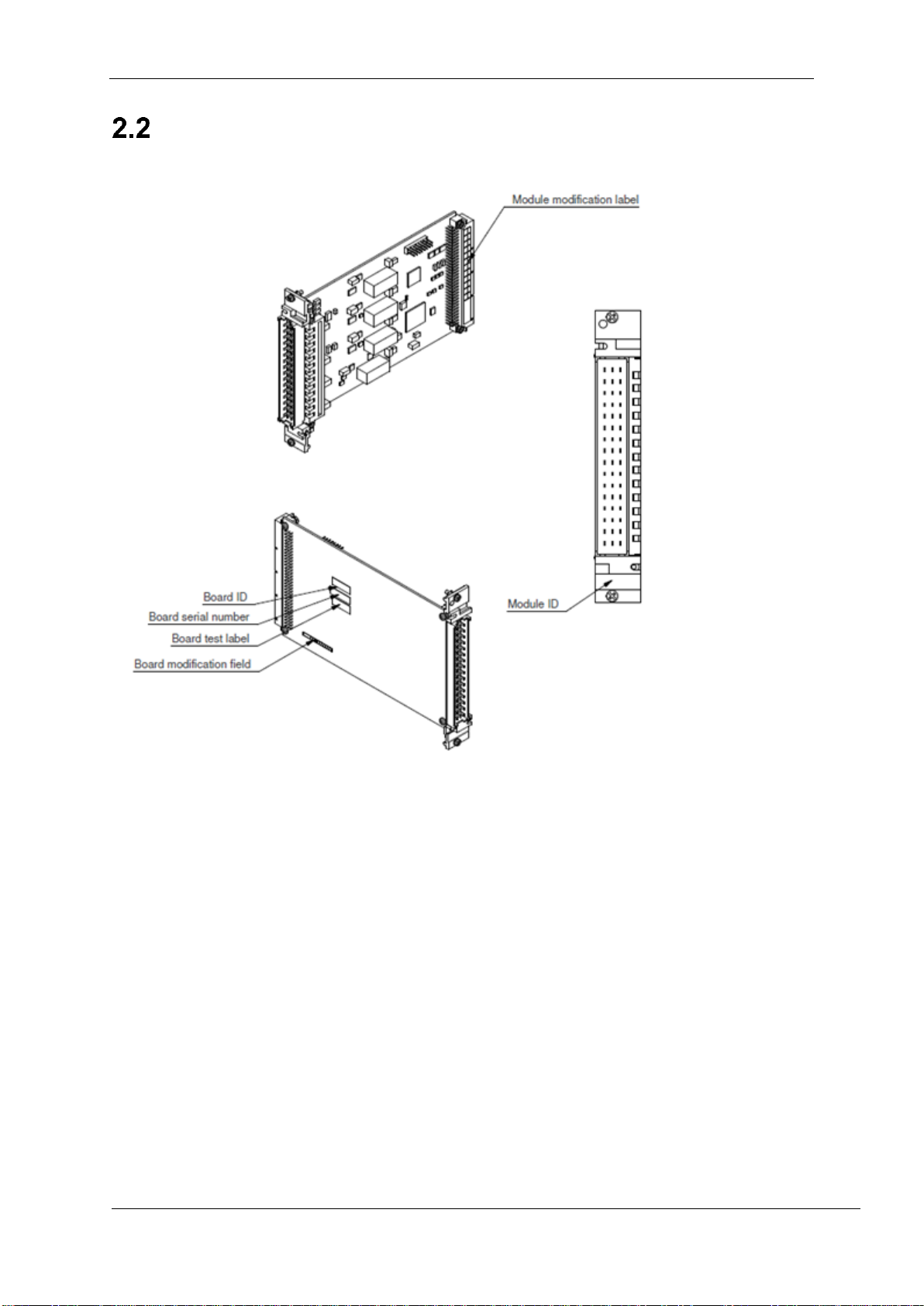
Module identification.................................................................................... 10
Functionality diagram................................................................................... 11
AIM module features.................................................................................... 11
2.4.1 Voltage and current inputs....................................................................... 12
2.4.2 Frequency inputs ..................................................................................... 12
2.4.3 Voltage supply outputs............................................................................. 12
2.4.4 Module temperature and self tests........................................................... 12
3. Installing the AIM module into a rack ............................................................... 13
Before the installation.................................................................................. 13
3.1.1 Warnings.................................................................................................. 13
3.1.2 Preparations ............................................................................................ 14
Installation procedure .................................................................................. 14
3.2.1 Installing the AIM module into the rack.................................................... 14
3.2.2 Installing the I/O cable on the module...................................................... 15
Checkingthat the module works correctly.................................................... 15
3.3.1 Memory Self Test..................................................................................... 15
3.3.2 Status Indicator LEDs.............................................................................. 16
3.3.3 Using the Portable System Tester (PST) software................................... 16
Potential problems in the installation procedure.......................................... 17
4. AIM Features and operation .............................................................................. 18
I/O Bus......................................................................................................... 18
Node addresses .......................................................................................... 19
4.2.1 Rack types............................................................................................... 19
I/O Connector pins....................................................................................... 19
Frequencyinputs (group 1).......................................................................... 20
Currentand voltage Input channels(groups 2, 3 and 4)................................ 21
Heartbeat..................................................................................................... 23
Module temperature..................................................................................... 23
Memory self test .......................................................................................... 23
5. AIM Binary Tree .................................................................................................. 24
AIM Binary tree Register map...................................................................... 24
5.1.1 Registers in detail .................................................................................... 28
6. Troubleshooting................................................................................................. 32
Warnings ..................................................................................................... 32
Preparations................................................................................................ 33
Visual check ................................................................................................ 33
6.3.1 Circuit board ............................................................................................ 33
6.3.2 Cabling..................................................................................................... 33
Getting started with troubleshooting ............................................................ 33
Opening the Remote Terminal connection .................................................. 35
Contents

General information
AIM2505A Technical Manual V2.03 4
Remote terminal commands........................................................................ 37
6.6.1 Notes on commands................................................................................ 37
6.6.2 Command help - print available commands............................................. 37
6.6.3 Command ver - version check................................................................. 37
6.6.4 Command ser - serial link diagnostic counters ........................................ 38
6.6.5 Command freq –print status of Frequency Inputs................................... 38
6.6.6 Command in [num] - print input channel values....................................... 38
7. Firmware loading................................................................................................ 39
8. Technical Specifications.................................................................................... 40
Mechanical specifications............................................................................ 40
Connectorand pin order specifications........................................................ 40
8.2.1 X1, IO Connector..................................................................................... 40
8.2.2 X2, VME CONNECTOR........................................................................... 41
8.2.3 X4, DLOAD CONNECTOR...................................................................... 42
Electrical specifications................................................................................ 43
Reliability specifications............................................................................... 43
Non-metallic parts........................................................................................ 44
Compliance with standards.......................................................................... 44
Environmental and EMC test specifications................................................. 45
9. Cable recommendations.................................................................................... 46
10. Diagrams ................................................................................................ 48
11. Disposal of the module ......................................................................... 50
EKE-Electronics Ltd. pursues a policy of continual product development. Although
every effort is made to produce up-to-date product documentation this publication should
not be regarded as an infallible guide to current specifications. We reserve the right to
make changes without prior notice.
COPYRIGHT EKE-ELECTRONICS LTD. 2016

General information
5AIM2505A Technical Manual V2.03
1. General information
This is the Technical Manual for the EKE-Trainnet® AIM2505A Analog Input Module.
This manual is for system user and for designers.
This manual contains following chapters:
Chapter 1: General information
Chapter 2: Overview of the AIM module
Chapter 3: Installing the AIM module into the rack
Chapter 4: AIM features and operation
Chapter 5: AIM Binary tree
Chapter 6: Troubleshooting
Chapter 7: Firmware loading
Chapter 8: Technical specifications
Chapter 9: Cable recommendations
Chapter 10: Diagrams
This manual does not include information on other EKE-Trainnet®
products than the AIM module. If you need information about other
EKE-Trainnet® products (e.g. modules, racks or accessories), refer to
the manual of the product in question.
This chapter includes general information about this manual. The following topics are
covered in this chapter:
About this manual
Symbols used in this manual
Safety considerations
Correct handling of the module
基本信息
AIM 模块的概述
AIM 模块安装到机架中
AIM 功能与操作
AIM 二进制树
故障排除
固件加载
技术规格
电缆推荐
图表

General information
AIM2505A Technical Manual V2.03 6
Symbols used in this manual
In this manual, situations that require caution are marked with special warning symbols.
The warning symbols appear in the beginning of the appropriate chapter. The following
symbols are used.
Figure 1.1 Electric shock warning symbol
Figure 1.2 ESD warning symbol
Figure 1.3 General caution symbol
Figure 1.4 Note symbol
Figure 1.5 Separate collection for Waste Electrical and Electronic Equipment according to
Directive 2002/96/EC (WEEE)

General information
7AIM2505A Technical Manual V2.03
Safety considerations
The AIM module is a low voltage device. In a normal situation, it presents no safety risk
to the user.
When the AIM module is in use, it will contain a charge from 8V to
36V, depending on the current loop voltage used. Never disconnect
the AIM module from the rack with active power. When you remove
an AIM module that has been in use, always turn off the rack power
first.
In case of a severe train malfunction or wiring errors, there is a risk of
an electric shock through the bus cables.
The rack and modules can contain sharp edges. Use protective
clothing (gloves etc.).
The protection components on the module are intended to protect
module only from external surges and transients. They do not provide
protection against incorrect wiring or connection.
Correct handling of the module
Electrostatic discharge (ESD) can damage electronic circuits. EKE products are
protected against ESD. However, you run the risk of delivering electrostatic discharges
to the module whenever you handle it or any of its components.
To avoid this risk, only handle the AIM module at a static-free workstation. If this is not
possible, you must ground yourself using a wrist strap and a resistive connection cord.
Remember to handle the module according to these instructions even when you are
removing a defective module and sending it to maintenance.
Remember to handle the module according to these instructions even
when you are removing a defective module and sending it to
maintenance.
静电放电会损坏电子线路。保护EKE产品免受静电放电。无论怎样,每当你处理模块或其任何组件时,都会有向模块发送静电的风
险。
为了避免这种风险,可以在防静电工作台上处理模块。如果还不能奏效,你必须带手环和接地线进行连接。即使在拿出有缺陷的模块
进行维护时也要按照这个指令操作。

Overview of the AIM module
AIM2505A Technical Manual V2.03 8
2. Overview of the AIM
module
This chapter lists selected specifications of the AIM module and highlights some of
its features.
The following topics are covered in this chapter:
Selected specifications
Module identification
Functionality diagram
AIM module features
选择规格
模块识别
功能图
AIM模块特征

Overview of the AIM module
9AIM2505A Technical Manual V2.03
Selected specifications
The EKE-Trainnet® AIM module is designed for receiving control information from
devices on board a train to the EKE-Trainnet® CPU.
This section lists some technical specifications of the AIM module.
Table 2.1 Selected specifications
Parameter
Value
Size of the AIM module printed circuit board
100x160 mm (Euro 1)
Width
4 TE
Height
3 U
Weight
160g
Required free space in front of the module
75 mm
Operating voltage
5 VDC (4.75…5.25 VDC)
Operating temperature
- 40...+70 °C
Analog inputs
Number of voltage inputs
10
Number of current inputs
10
Voltage input range
-10...10 V
Current input range
-20...+20 mA
Accuracy
±0.4% of full scale (12 bit)
Frequency inputs
Number of frequency inputs
4
Input range
0…16 kHz
Input resolution
0...16 kHz
Input accuracy
0.25 Hz
Input voltage
± 0.1%
Input positive going threshold
8 V
Input negative going threshold
7 V
Reliability, MTBF, greater than (FIT data at +40°C ambient)
250 000 h
AIM 模块是从列车上的设备接收控制信息给CPU模块。
AIM电路板模块的尺寸
宽
长
重量
模块前所需空间。·
工作电压
工作温度
模拟输入
频率输入
电压输入值
电流输入值
电压输入范围
电流输入范围
准确率
频率输入值
输入范围
输入分辨率
输入精确值
输入电压
输入正向极值
输入负向极值
可靠工作时间

Overview of the AIM module
AIM2505A Technical Manual V2.03 10
Module identification
The following figure shows where to find the version and the modification
information.
Figure 2.1 The location of version and modification information
A modification label shows the module modification. It is located on the back
connector. The label includes letters, and the modification is indicated by crossing
out one. If letter A is crossed out, the modification is A, and so on. This modification
field is for the entire module.
The circuit board may have a different modification level, indicated by numbers,
which are printed on the board’s modification field. This is found on the back side of
the circuit board on the lower left section.
The Board test label indicates that the module has gone through the required testing
cycle. It is located above the board modification field.
The Board serial number identifies the module. It is located above the board test
label.
The Board ID above the Board serial number indicates an ID for the circuit board.
The Module ID located just below the front connector indicates an ID for this entire
module.
下图显示在哪里找到版本和修改信息。
模块修正标签
模块ID号
板卡ID号
板卡序列号
板卡测试标签
板卡修正区域
修正标签展示模块的修正版本,它位于背面的连接处。标签包含字母和修改表示被划掉的一个部分。如果字母A被划掉,修改的就是A,等等。
这个修改区域是对整个模块的。
电路板可以有不同的修改级别,用数字表示,在板的修改字段上打印。这个
位于电路板的左下角。
板卡测试标签证明了模块通过了要求的测试周期。它位于板
卡修改区域上方。
板卡序列号用于证明模块,它位于板卡测试标签的上方。
板卡ID号位于板卡序列号的上方,证明电路板的ID号。
位于前连接器下方的模块ID指示此模块的ID号。

Overview of the AIM module
11 AIM2505A Technical Manual V2.03
Functionality diagram
The following figure (Fig. 2.2) presents a general diagram of the AIM module
functionality. Channels are divided into four isolated groups which are galvanically
isolated from each other and from control electronics.
Group 1 has four frequency inputs and two voltage output pins for external sensor or
current loop.
Group 2 has two voltage and current inputs.
Groups 3 and 4 are identical and they have four voltage and current inputs and one
voltage output pin for external sensors or current loops.
Figure 2.2 Functionality diagram of the SIU module, SIU3449A represented.
AIM module features
The AIM module is an intelligent analog input interface module that can be located in
the Coach Computer or distributed within the coach. The module has its own 32-bit
embedded processor and a serial bus interface for communication with the Coach
Computer’s (EKE-Trainnet® Gateway) CPU.
第1组有四个频率输入和两个电压输出引脚在外部传感器或电流环。
第二组有两个电压和电流输入。
第三组和第四组是相同的,它们有四个电压和电流输
入,还有一个电压输出针脚在外部传感器或电流环。
AIM模块是一个智能模拟输入接口模块,可以位于车厢计算机或分布在旅
客车厢内。该模块拥有自己的32位嵌入式处理器和一个与车厢计算机CPU
通信的串行总线接口(EKE trainnet®网关).

Overview of the AIM module
AIM2505A Technical Manual V2.03 12
2.4.1Voltage and current inputs
Each of the 10 voltage and current channels have similar measurement range.
Voltage inputs
The nominal input voltage range is -10...+10V. All the parameters are specified over
this range. Actual measurement range which is -12...+12V exceeds the nominal input
range and allows overrange detection. Measurement resolution is 13 bits and the
step size in the input register is 10 mV.
Current inputs
The current input is compatible with the industry standard 4...20mA current loops (2-
wire receiver according to the standard ANSI/ISA-50.1-1982 (R1992)). The nominal
input range is extended to -20...+20mA. All the parameters are specified over this
range. Actual measurement range which is -25...+25mA exceeds nominal input
range and allows overrange detection. Measurement resolution is 13 bits and the
step size in the input register is 10µA.
2.4.2Frequency inputs
The frequency inputs can be used to measure frequency, pulse width ratio and pulse
count. The input frequency range is 0...16 kHz. The frequency accuracy is better
than 1000 ppm which is 16 Hz at full range. Frequency measurement resolution is
0.25 Hz.
2.4.3Voltage supply outputs
Groups 1, 3 and 4 have output voltage supply pins that can be used to supply
voltage to external sensors or used to supply loop voltage to the current loops.
Output supply voltage is 15V nominal and it can supply 100mA current per group.
2.4.4Module temperature and self tests
The module has a sensor that measures the temperature of the module continually
with 3 ºC (Celsius) accuracy, and informs the Coach Computer CPU about it.
When the module is installed in a rack and the power turned on, the module
performs memory tests on itself to make sure it is functioning correctly.
电压和电流的10个频道中的每一个都有相似的测量范围。
普通的电压输入范围是-10V到10V之间。所有参数都在此范围内指定。实际测
量范围是在-12V到12V的超标普通输入范围和允许的超标的区域。测量分辨率
为13位,在输入寄存器的步长为10毫伏。
频率输入可用于测量频率,脉冲宽度比和脉冲计数.输入频率的范围是0到16kHz。频率精度优于1000 ppm的16 Hz全量
程。频率测量分辨率为0.25赫兹。
组1,3和4有输出电压引脚,可用于供应电压外部传感器或用于提供回路电压的电流回路。输出电压一般是15V,它提供100mA电流
每组。
该模块具有一个传感器测量模块的温度持续3ºC(摄氏度)的精度,并通知给有关车厢电脑CPU。
当模块安装到机架上,电源打开,该模块对自己进行内存测试,以确保它的功能正确。

Installing the AIM module into a rack
13 AIM2505A Technical Manual V2.03
3. Installing the AIM module
into a rack
This chapter includes instructions on how to install the EKE-Trainnet® AIM module
into a rack.
The following topics are covered in this chapter:
Before the installation
Installation procedure
Potential problems in installation procedure
Before the installation
3.1.1Warnings
This section contains warnings you need to consider before and during the AIM
module installation.
Do not turn on the rack power before you have finished the
installation of the rack.
Never remove the AIM module from a rack. Always turn OFF the rack
power first BEFORE removing the rack.
Electrostatic discharge can damage electronic circuits. Always handle
the module at a static free workstation. If this is not possible, ground
yourself using a wrist strap and a resistive connection cord.
The module and also the rack can contain sharp edges. Use
protective clothing (gloves etc.).
Do not drop the module.
Make sure that the module or any of the components on it do not get
wet.
When handling the module, only touch the front panel. Do not touch
the board or any of the components on it. Even when you are
removing a defective module and sending it to maintenance, handle
the module according to these instructions.

Installing the AIM module into a rack
AIM2505A Technical Manual V2.03 14
3.1.2Preparations
Before you start installing the AIM module to a rack, make the following preparations.
Make sure you have a Pozidrive Pz0 or Pz1 screwdriver to tighten the front
panel fastening screws on the module.
Check the shipping container to see that it is not damaged.
Take the module out of its shipping container carefully. The module is always
shipped in an ESD protective wrapping.
Check the module, especially the connectors, for any visible signs of damage
that may have occurred during shipment.
Installation procedure
The following sections include instructions for installing the AIM module into a rack.
3.2.1Installing the AIM module into the rack
1. Check that the coding pins are installed according to the project specifications
2. Hold the module by the front connector.
3. Place the module on the rails of the rack.
4. Slide the module towards the back plane of the rack until it clicks into its
place. Do not use force.
5. Tighten the two screws (Pozidriv head collar screws) on the front panel.
6. If there are other modules in the rack, make sure that the front connector of
the AIM module is at the same level with the other modules.
If the module does not fit into its place in the rack refer to section 3.4 “Potential
problems in the installation procedure” on page 17.
检查编码引脚是否按照项目规范安装。

Installing the AIM module into a rack
15 AIM2505A Technical Manual V2.03
The following picture shows a sample rack with modules successfully installed. The
modules in the picture are just an example, and the picture is intended as illustration
only.
Figure 3.1 Modules installed in a rack
3.2.2Installing the I/O cable on the module
1. Check that the coding pins on the cable connectors are installed according to
the project specifications.
2. Check that the installed I/O cable fulfils the cable requirements described in
the Cable Recommendations chapter.
3. Connect the cable to the module I/O interface without using force.
4. Tighten the two (2) attachment screws of the cable connector.
Checking that the module works correctly
3.3.1Memory Self Test
When the module is installed in a rack and the power turned on, the module
performs memory self test to verify correct operation.In case the module does not
pass the self tests an error will occur and the red LED located on the circuit board
will light on (refer to Table 3.2).
AIM module

Installing the AIM module into a rack
AIM2505A Technical Manual V2.03 16
3.3.2Status Indicator LEDs
There are three status indicator LEDs (green and red) on the circuit board, which can
be seen if there are no other modules next to it in the rack (refer to “Module
identification” on page 10).
Table 3.1 Indicator LEDs and their functions
Colour
Reference
designator
Name
Meaning when
Off
On
Blinking
Red
H1
System error
(SE)
System OK
System error
occurred,
module in
reset
Self-tests failed
Green
H2
Status
(ST)
If SE (red) led
is also off, no
power
System OK
System OK,
communication
with host CPU
Green
H3
FPGADONE
FPGA Not
initialized,
module in
reset
System OK,
FPGA
initialized
Module in “reset-
loop”
If all leds are off, there is no power provided to the module.
3.3.3Using the Portable System Tester (PST) software
The EKE-Trainnet Portable System Tester (PST) software can be used to examine
the AIM module’s operation through the Coach Computer. For further details and
instructions refer to the PST User’s Manual.

Installing the AIM module into a rack
17 AIM2505A Technical Manual V2.03
Potential problems in the installation procedure
The following table lists some potential problems that can occur during the AIM
module installation, as well as their causes, and actions you can take to solve the
problem.
Table 3.2 Potential problems in the installation procedure
Problem
Potential cause
Action
The module does not fit into
the rack.
The connector pins of the
module are damaged.
Replace the module with a
spare one.
Connector pins are OK, but
the module does not fit into
the rack.
The back plane of the rack
is damaged.
Refer to the documentation
provided by the rack
manufacturer.
The module is installed
correctly into the rack, but it
is not working.
The module is damaged.
Replace the module with a
spare one.
The installed module is not
working and the red LED is
on or blinking on the circuit
board (refer to “Indicator
LEDs and their functions”
on page 16).
System error
Replace the module with a
spare one.

AIM Features and operation
AIM2505A Technical Manual V2.03 18
4. AIM Features and
operation
This chapter includes a brief description about the AIM firmware.
The following topics are covered in this chapter:
I/O-bus
Node address
Input channels
Other AIM module feature
I/O Bus
The AIM module is compatible with EKE-Trainnet® Common I/O-bus (later referred
to as I/O-bus). The I/O-bus is available in several EKE-Trainnet® Coach Computer
central processing units like CPU, CPG, CPR etc. In this document all these units
are referred to as CPU.
The following figure shows the principal connection between the AIM module and the
CPU.
Figure 4.1 AIM-CPU connection
On the CPU side, an I/O-bus master called CIAO manages all communication
between the AIM module and the CPU. The CIAO transfers all data coming from the
AIM module into Binary tree registers. An ISaGRAF application can read this data
from the Binary tree. In the same manner, if the ISaGRAF application wants to send
something to the AIM module, it writes the data to the Binary tree.
The CIAO transfers all data from the Binary tree registers to the AIM module. The
Binary tree register addresses and the contents of each register are explained in
Chapter 5: AIM Binary Tree.

AIM Features and operation
19 AIM2505A Technical Manual V2.03
Node addresses
There can be several I/O modules connected to one I/O-bus. To be able to separate
all I/O modules from each other, they must have a unique node address. A unique
node address is assigned to each I/O module depending on their slot position in a
rack. At power-up, every I/O module reads a physical address that is coded to the
rack backplane. Based on this physical address, the I/O module selects a node
address. Different rack type backplanes are coded differently. The I/O-bus node
address is thus dependent on both in what slot and in which rack type the module is
in.
4.2.1Rack types
Please refer to corresponding rack manual for information about
racks and IO bus slot addresses.
I/O Connector pins
The following table show each channel and its related pins on connector X1.
Table 4.1 AIM IO Connector pinout
Connector X1
Pin
Signal
Pin
Signal
Pin
Signal
z32
GROUP4VSSI
b32
CURR10
d32
VOLT10
z30
GROUP4VSSI
b30
CURR9
d30
VOLT9
z28
GROUP4VSSI
b28
CURR8
d28
VOLT8
z26
GROUP4VSSI
b26
CURR7
d26
VOLT7
z24
PE
b24
PE
d24
GROUP4VOUT
z22
GROUP3VSSI
b22
CURR6
d22
VOLT6
z20
GROUP3VSSI
b20
CURR5
d20
VOLT5
z18
GROUP3VSSI
b18
CURR4
d18
VOLT4
z16
GROUP3VSSI
b16
CURR3
d16
VOLT3
z14
PE
b14
PE
d14
GROUP3VOUT
z12
GROUP2VSSI
b12
CURR2
d12
VOLT2
z10
GROUP2VSSI
b10
CURR1
d10
VOLT1
z8
PE
b8
GROUP1VOUT
d8
PE
z6
GROUP1VSSI
b6
GROUP1VOUT
d6
FREQ3
z4
GROUP1VSSI
b4
GROUP1VSSI
d4
FREQ2
z2
GROUP1VSSI
b2
FREQ4
d2
FREQ1
FREQ = Frequency/pulse count
CURR = Current Input
VOLT = Voltage Input
PE = Protection Earth
GROUPxVSSI = Group ground (return, wire)
GROUPxVOUT = Group voltage supply output

AIM Features and operation
AIM2505A Technical Manual V2.03 20
Frequency inputs (group 1)
AIMmodulehasfourfrequencyinputs that can be used for measuringinput frequency,
input pulse count and input pulse width ratio.
They can also be used as plain digital inputs.
Figure 4.2 Frequency input block
Additionally, inputs FREQ1 and FREQ2 (see table 4.5) can be paired to measure
phase direction between two signals of the same frequency that are phase shifted in
respect to each other. Another pair can be made from FREQ3 and FREQ4. This
enables applications such as measurement of train travel distance to be aware of
travel direction, which then can be used (with pulse counting) to estimate train
location on track.
Figure 4.3 Example of direction sensing capable tachometer
Frequency inputs have fixed positive going threshold level of 8V and negative going
threshold level of 7V. Input voltage range is specified up to 36V.
The GROUP1VSSI pins (refer to Table 4) on all channels are internally connected
together and therefore no voltage difference between GROUP1VSSI pins are
allowed.
Table of contents
Other EKE-Electronics Control Unit manuals