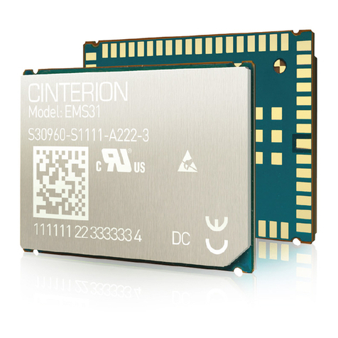
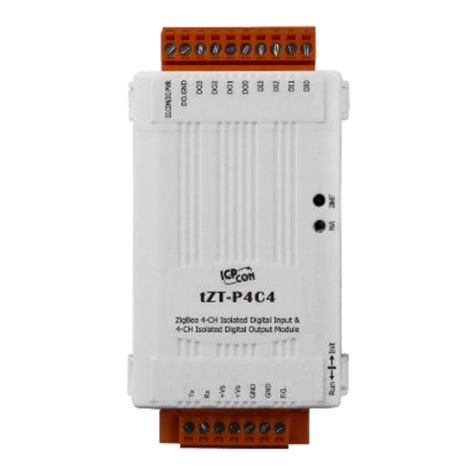
EKE-Electronics EKE-Trainnet DIO2908A User manual

EKE-Trainnet®
DIO2908A
Digital Input Output Module
DIO SIL Technical Manual

EKE-Electronics Ltd.
Piispanportti 7, FIN-02240 Espoo, FINLAND
Tel. +358 9 6130 3308
Fax +358 9 6130 3300
e-mail: electronics@eke.com
Marketing and sales
e-mail: electronics@eke.com
TMS implementations, passenger train functions and
IEC 61131-3 type application programming
e-mail: electronics@eke.com
Technical support and maintenance requests
e-mail: [email protected]om
The most recent information on EKE Electronics’ products and services is available at www.eke.com.
Under copyright law no part of this document may be copied, reproduced or transferred electrically or
manually, not even partly, without prior written permission of EKE-Electronics Ltd. This document is subject
to change without notice.
The EKE-Trainnet® is a registered trademark of EKE-Electronics Ltd.
Copyright © 2013 EKE-Electronics Ltd. All rights reserved.
EKE-Trainnet®DIO2908A Digital Input Output Module SIL Technical Manual ver. 1.00

1. General information ............................................................................................. 4
Symbols used in this manual......................................................................... 51.1
Safety considerations .................................................................................... 61.2
1.2.1 Considerations in safety system design..................................................... 6
Correct handling of the module...................................................................... 61.3
Disposal of the module.................................................................................. 61.4
2. DIO module features and operation.................................................................... 8
Module identification...................................................................................... 82.1
DIO module features.................................................................................... 102.2
DIO module- Secure Application connection............................................... 112.3
Inputs........................................................................................................... 122.4
2.4.1 Input wetting current ................................................................................ 12
2.4.2 Input read rate.......................................................................................... 12
2.4.3 Input thresholds....................................................................................... 12
2.4.4 Input self-test ........................................................................................... 13
2.4.5 Data reply message................................................................................. 13
Outputs........................................................................................................ 152.5
2.5.1 Output control.......................................................................................... 15
2.5.2 Output readback ...................................................................................... 16
2.5.3 Output protection ..................................................................................... 16
2.5.4 Outputs at startup .................................................................................... 18
2.5.5 Output emergency states......................................................................... 18
3. Installation........................................................................................................... 19
Warnings ..................................................................................................... 193.1
Cable Recommendations ............................................................................ 203.2
3.2.1 I/O cable .................................................................................................. 20
3.2.2 Installing the I/O cable on the module...................................................... 21
4. Technical data..................................................................................................... 22
Non-metallic parts........................................................................................ 224.1
I/O Connector (X1)....................................................................................... 234.2
Electrical specifications................................................................................ 244.3
Reliability..................................................................................................... 254.4
Safety .......................................................................................................... 254.5
Insulation and voltage withstand.................................................................. 254.6
Environmental and EMC test specifications................................................. 264.7
Contents
EKE-Electronics Ltd. pursues a policy of continual product development. Although
every effort is made to produce up-to-date product documentation this publication should
not be regarded as an infallible guide to current specifications. We reserve the right to
make changes without prior notice.
COPYRIGHT EKE-ELECTRONICS LTD. 2013

General information
DIO2908A SIL Technical Manual ver. 1.00 4
1. General information
This is the SIL Technical Manual for the EKE-Trainnet® DIO2908A Digital Input Output
H module.
This manual is for system user and for designers.
This manual contains following chapters:
Chapter 1: General information
Chapter 2: DIO module features and operation
Chapter 3: Installation
Chapter 4: Technical data
This manual does not include information on other EKE-Trainnet®
products than the DIO SIL module. If you need information about
other EKE-Trainnet® products (e.g. modules, racks or accessories),
refer to the manual of the product in question.
This chapter includes general information about this manual. The following topics are
covered in this chapter:
Symbols used in this manual
Safety considerations
Correct handling of the module
Disposal of the module

General information
5DIO2908A SIL Technical Manual ver. 1.00
Symbols used in this manual1.1
In this manual, situations that require caution are marked with special warning symbols.
The warning symbols appear in the beginning of the appropriate chapter. The following
symbols are used.
Figure 1.1 Electric shock warning symbol
Figure 1.2 ESD warning symbol
Figure 1.3 General caution symbol
Figure 1.4 Note symbol
Figure 1.5 Separate collection for Waste Electrical and Electronic Equipment according to
Directive 2002/96/EC (WEEE)

General information
DIO2908A SIL Technical Manual ver. 1.00 6
Safety considerations1.2
It is not allowed to remove the DIO module from system / rack. It
is also not allowed to update the module software or to perform
module level diagnostics or repairs.
1.2.1Considerations in safety system design
It is not possible to detect all possible module internal errors. It is recommended to use
the following design guidelines:
The safe-state design approach and output readback should be implemented on
application level.
To increase availability the system level redundancy should be implemented.
In case there is communication error on the module level the module safe state
will be activated (refer to chapter 2.5.5 on p.18).
Correct handling of the module1.3
Electrostatic discharge (ESD) can damage electronic circuits. EKE products are
protected against ESD. However, you run the risk of delivering electrostatic discharges
to the module whenever you handle it or any of its components.
To avoid this risk, only handle the DIO module at a static-free workstation. If this is not
possible, you must ground yourself using a wrist strap and a resistive connection cord.
Remember to handle the module according to these instructions even when you are
removing a defective module and sending it to maintenance.
Disposal of the module1.4
In order to reduce the environmental load over the product’s entire lifecycle,
EKE-Electronics’ products are designed to be as safe as possible to manufacture, use,
and dispose of
Parts which can be recycled should always be taken to the appropriate processing
centres, after hazardous waste has been removed. All parts and components containing
hazardous materials must be disposed of in accordance with waste legislation and
instructions issued by the environmental authorities. The risks involved and the
necessary precautions must be taken into account when handling waste products.
Therefore, please execute proper processing of disposal in accordance with local law.

General information
7DIO2908A SIL Technical Manual ver. 1.00
Table 1.1 Disposal of the DIO module, X = action, (X) = action in cases where
processing is available
Part Main materials
of disposal Recyclable
materials Waste disposal
sites Hazardous waste
(separate
collection)
Frame and
covers
Metal
Plastic
Rubber
Aluminium
Stainless steel
PUR, PU
Other plastics
X
X
X
X
X
Component
boards
Lead
(X)
X
Packing
Cardboard
PE X
X

DIO module features and operation
DIO2908A SIL Technical Manual ver. 1.008
2. DIO module features and
operation
This chapter includes information about DIO module functionality and features.
Module identification
DIO module features
DIO module – Secure Application connection
Inputs
Outputs
Module identification2.1
The following figure shows where to find the version and the modification
information.

DIO module features and operation
9DIO2908A SIL Technical Manual ver. 1.00
Figure 2.1 The location of version and modification information
A modification label shows the module modification. It is located on the back
connector. The label includes letters, and the modification is indicated by crossing
out one. If letter A is crossed out, the modification is A, and so on. This modification
field is for the entire module.
The circuit board may have a different modification level, indicated by numbers,
which are printed on the board’s modification field. This is found on the back side of
the circuit board on the lower left section.

DIO module features and operation
DIO2908A SIL Technical Manual ver. 1.0010
The Board test label indicates that the module has gone through the required testing
cycle. It is located above the board modification field.
The Board serial number identifies the module. It is located above the board test
label.
The Board ID above the Board serial number indicates an ID for the circuit board.
The Module ID located just below the front connector indicates an ID for this entire
module.
DIO module features2.2
The DIO module has 32 channels. From all the channels 24 are inputs and eight (8)
may function as either input or output .The Input and Input/Output channels are
divided into two groups that can have different Group Voltages (e.g. 110 V and 24
V). The two groups are not galvanically isolated.
The following figure presents a general functionality diagram of the DIO module.
Figure 2.2 Functionality diagram of the DIO module (I=Input, I/O=Input/Output)

DIO module features and operation
11 DIO2908A SIL Technical Manual ver. 1.00
The states of inputs and readback from outputs are transmitted to the system CPU
trough backplane serial link, along with diagnostic data. The states of outputs can
are controlled from system CPU with a command message.
DIO module has continuous self-test functionality for all channels. Data from self-test
can be used by applications running on the system CPU, for system wide
diagnostics and data logging.
Input measurement and channel diagnostics have a cycle time under 100ms, that is,
all channels are measured within that time and new input state data and self-test
data is available for system CPU each time when polled with 100ms period.
Hardware supervision circuits watch the modules operating voltages. If any of them
is out of specifications, the module will reset itself. A hardware watchdog resets the
module if the firmware gets stuck for any reason.
The DIO module has an internal heartbeat counter that can be used to check that the
module is alive. It has also a dedicated sensor that measures the temperature of the
module periodically with 3 °C accuracy.
For additional diagnostic use, after reset the module will set a reset flag bit high for
first data reply message. This flag will be low after first such message.
During start-up the module performs a program memory test to make sure that the
firmware can function correctly. If a memory corruption is detected, module will not
respond to messages from SA but waits for rack reset (or power cycle).
DIO module- Secure Application connection2.3
The DIO module communicates with Secure Application (SA) running on the system
CPU through RS485 serial link in the rack backplane. The protocol framing includes
heartbeat, MD5 hash (for output command and data reply messages) and CRC-16
checksum for message data integrity.
The protocol and full content of various messages are not detailed in
this document.

DIO module features and operation
DIO2908A SIL Technical Manual ver. 1.0012
Figure 2.3 SA(HOST)-CPU connection
Inputs2.4
The DIO has 24 input channels. In addition any number of the eight output channels
can be used as a normal input when set to high impedance state.
2.4.1Input wetting current
Input load, or wetting current, is set to 20.0 mA regardless of the Group Voltage.
This constant current load is applied to each input only for the time when it is being
sampled. During sampling of other channels load current will be zero.
This means that device connected to an input sees a pulsed load, which may need
to be taken into consideration when selecting an input device.
2.4.2Input read rate
The DIO polls the inputs sequentially, one at a time. Cycle time to read all inputs
(and/or output readback) and perform input channel self-test is under 100ms.
2.4.3Input thresholds
The voltage from an input pin is measured and the input state is determined relative
to the Group Voltage in following way:
•If the voltage is below 40% of the Group Voltage, the input state is zero (0).
•If the voltage is above 60% of the Group Voltage, the input state is one (1).
•If the voltage is between 40% and 60% of the Group Voltage, the input retains
its value, thus providing hysteresis of 20% of the Group Voltage.

DIO module features and operation
13 DIO2908A SIL Technical Manual ver. 1.00
2.4.4Input self-test
All inputs have a self-test function which use dedicated hardware controlled by
firmware. Self-testing is continuous and part of the input sampling cycle.
2.4.5Data reply message
Following data is sent from DIO module to SA.
Table 2.1 Data in reply message from DIO to SA
Bytes Field Range Notes
1 Inputs 25..32 / Output ..8
readback 0x00..0xFF If outputs are in high impedance state,
they can be used as inputs
1 Inputs 17..24 0x00..0xFF
1 Inputs 9..16 0x00..0xFF
1 Inputs 1..8 0x00..0xFF
1 Heartbeat 0x00..0xFF Increases for every data reply, wraps to
0x00 after 0xFF
1 Module temperature in °C -55°C..125°C Resolution is 1°C (8 bit signed value)
1 Group 1 voltage 0V..255V Measured value in volts
1 Group 2 voltage 0V..255V Measured value in volts
1 Module status 0x00..0xFF Status bits are explained in table below
1 Reset status 0 or 1 1 for first data query after reset (boot-
up), 0 for subsequent queries
16 MD5 Message digest Calculated from all bytes above

DIO module features and operation
DIO2908A SIL Technical Manual ver. 1.0014
Module status field bits contain information about Group Voltages and various input
self-test steps which can be used for diagnostic purposes.
Module status is zero when everything is normal. Any non-zero value indicates an
error.
Table 2.2 Module status bits (for all bits, 0 is OK and 1 signals error)
Bit Contents Primary cause Note
7 ITEST 6 Input multiplexer leak detected HW error
6 ITEST 5 Measured wetting current out of
range detected HW error or device connected to input
presents too high impedance.
5 ITEST 4 Measured input test voltage out
of range detected HW error
4 ITEST 3 Input test readback state error
detected (there are three
separate tests)
HW error
3 ITEST 2
2 ITEST 1
1 Group 2
voltage status Group 2 voltage under 14.4V or
over 154V These bits can be used to detect if
Group Voltage circuit breaker is off
(same as undervoltage).
Overvoltage may damage transient
suppressors.
0 Group 1
voltage status Group 1 voltage under 14.4V or
over 154V
It is important to note that all ITEST bits are common to all channels. If any input channel
signals an error in any self-test step, corresponding bit is set in module status. It is therefore
not possible to find which channel has an error.
Because all ITEST errors are most likely hardware related, it is reasonable to treat module
as faulty and in need of service if any channel shows self-test error.
However, ITEST 5 error can be caused by a device connected to an input if it cannot
pass required wetting current through. For example, 24V Group Voltage requires
1.2kΩor less to achieve 20mA wetting current.

DIO module features and operation
15 DIO2908A SIL Technical Manual ver. 1.00
Outputs2.5
The DIO has eight (8) output channels. Each can be set to high impedance state or
to output the Group Voltage. The output channels are in high impedance state as a
default. When set to a high impedance state an output channel can be used as an
input channel.
2.5.1Output control
The output states are controlled by the SA application with output control command.
Table 2.3 Data output control command from SA to DIO
Bytes Field Range Notes
1 Output
mask 0x00..0xF
F Only those outputs change state which have mask bit set.
Those that have mask bit cleared are unchanged.
1 Output
state 0x00..0xF
F State of output if corresponding mask bit is set.
1 Heartbeat 0..255 Must be different for each successive command, otherwise
command is discarded and error reply is returned.
16 MD5 Message
digest Calculated from three bytes above. DIO recalculates this
when a command has been received and makes a
comparison to received MD5. In case of mismatch,
command is discarded and error reply is returned.
Table 2.4 Channel bits in output write mask and output state fields
Bit
Description
7
Output channel 8
Group 1, supplied
from IOVCC(1)
6
Output channel 7
5
Output channel 6
4
Output channel 5
3
Output channel 4
Group 2, supplied
from IOVCC(2)
2
Output channel 3
1
Output channel 2
0
Output channel 1
If a bit in output mask is set and output state is cleared, the corresponding output is
driven to high impedance state. The voltage on the output pin is then 0 V (or, more
accurately, the voltage depends on the circuitry connected to the output).

DIO module features and operation
DIO2908A SIL Technical Manual ver. 1.0016
If the bit in output mask is set and output state is set, the output is driven to high
state. In high state the output voltage is the same as the Group Voltage, which is
IOVCC(1) for outputs 1 to 4 and IOVCC(2) for outputs 5 to 8.
2.5.2Output readback
The actual states of output channels are returned in reply message as inputs 25..32.
This readback functionality can be used to verify at what state the output really is,
especially when it is commanded to high impedance state.
If an output has been commanded to high state and readback shows low state,
probable causes can be (but not limited to):
•Output overcurrent protection has activated
•Group voltage is missing
•Module hardware failure
If an output has been commanded to low state and readback shows high state,
probable causes can be (but not limited to):
•External device is driving output into high state
•Module hardware failure
•
2.5.3Output protection
Output channel overload protection hardware protects against short circuit and
against overtemperature. Overload protection activation time depends on the amount
of the overcurrent. Heavy loads will activate the protection faster. If current through
the channel causes excessive heat the channel is also shut down.
The following diagram illustrates overload protection reaction time (trip time) in
relation to load current.

DIO module features and operation
17 DIO2908A SIL Technical Manual ver. 1.00
Figure 2.4 Overload protection reaction time versus load current
Measured values can slightly vary depending on the system
configuration but the variation is so small that it has no impact on
normal operation.
The following diagram illustrates the trip current which causes the overload
protection to trip in less than 10ms. It also shows the Hold currents which will never
cause the protection to trip.
Figure 2.5 Output overcurrent versus temperature (Trip and Hold current)

DIO module features and operation
DIO2908A SIL Technical Manual ver. 1.0018
Measured values can slightly vary depending on the system
configuration but 1A hold current is guaranteed over allowed
operating temperature range.
When overload protection activates, the output changes to high impedance (low)
state and stays in that state until the cause for the short circuit is removed, either by
disconnecting load or shutting off Group Voltage.
The module firmware reads the state of the output channels and returns states to the
SA in a reply message. Diagnostic information can be obtained by comparing
commanded output state with output readback state.
2.5.4Outputs at startup
All 8 outputs are in low state after startup (driven to high impedance).
2.5.5Output emergency states
The output channels have a watchdog functionality that automatically drives the
outputs into low state if the communication between the DIO and the SA is lost or the
output command message is not correct for a time period longer than 500 ms.
The DIO will set the outputs back to commanded state as soon as the
communication with SA resumes and command message is correct again. The
emergency time is reset to 500 ms as well.

19 DIO2908A SIL Technical Manual ver. 1.00
3. Installation
This chapter includes instructions on how to install the EKE-Trainnet® DIO module
into a rack.
The following topics are covered in this chapter:
Warnings
Cable Recommendations
Warnings3.1
This section contains warnings you need to consider before and during the DIO
module installation.
Do not turn on the rack power before you have finished the
installation of the rack.
Never remove the DIO module from a rack. . Always turn OFF the
rack power first BEFORE removing the rack.
Electrostatic discharge can damage electronic circuits. Always handle
the module at a static free workstation. If this is not possible, ground
yourself using a wrist strap and a resistive connection cord.
The module and also the rack can contain sharp edges. Use
protective clothing (gloves etc.).
Do not drop the module.
Make sure that the module or any of the components on it do not get
wet.
When handling the module, only touch the front panel. Do not touch
the board or any of the components on it. Even when you are
removing a defective module and sending it to maintenance, handle
the module according to these instructions.

Installation
DIO2908A SIL Technical Manual ver. 1.0020
Cable Recommendations3.2
3.2.1I/O cable
The I/O cable has to have at least 0.5mm2 cross-section.
In the module all IOVCC(1) internally connected to each other. The same applies to
IOVCC(2) and OGND pins. This depends on the used maximum output current. The
maximum current through one connector pin is 3.5A at +85°C.
The output channels constitute the most of the all current through I/O
connector. It is necessary to connect at least two (2) wires to
IOVCC(1) and two (2) wires to IOVCC(2) because the maximum
current through one output channel is 1.4A. Also at least one (1) wire
shall be connected to IOGND pins.
If group voltage is connected to both IOVCC (1) and IOVCC (2) then
the group-voltage-out-of-range error bit will be set and the safety
application does not work correctly.
The following tables includes I/O cable parts and tools needed to manufacture the
I/O cable.
Table 3.1 I/O cable part list
Description Manufacturer Type
Cable >0.5mm2 cross-section
Connector Harting 09 06 248 3201
Housing Harting 09 06 048 0521
Code comp Harting 09 06 000 9984
Code pin Harting 09 06 001 9905
Crimp contact Harting 09 06 000 8471
Connector Harting 09 06 000 8472
Table of contents
Other EKE-Electronics Control Unit manuals
