I
- ITALIANO
Dati conformi alla normativa EIA RS485.
AlImENtAzIoNE
Tensione nominale: 230 VCA ±20% / 50 Hz
Massima tensione ripetitiva: 300 VCA
Massima tensione di picco non ripetitiva: 320 VCA (20 ms)
Consumo: max 5 VA
Fusibile: tipo T, 100 mA (da montare esternamente)
ComUNICAzIoNE RS485
Protocollo: MODBUS RTU (8N1) e ASCII (7E2)
Porta: RS485
Velocità di comunicazione: 300...57600 bps
Resistenza di terminazione integrata nel modulo: 120 Ohm
ComUNICAzIoNE SERIAlE
Tipo: porta ottica
Velocità di comunicazione: 38400 bps
NoRmE DI CoNFoRmItA’
EN 61000-6-2 Immunità per ambienti industriali:
EN 61000-4-2 Compatibilità elettromagnetica, EN 61000-4-3 Immunità a RF irradiata,
EN 61000-4-4 Immunità al burst/fast transient, EN 61000-4-5 Immunità ai surge (Surge),
EN 61000-4-6 Immunità a RF condotta, EN 61000-4-11 Immunità ai dips sull’alimentazione AC
EN 55011 classe A: emissioni irradiate, emissioni condotte
Sicurezza: EN 60950
DIAmEtRo FIlo PER moRSEttI DI CoNNESSIoNE
Morsetti: 0,14...2,5 mm2
CoNDIzIoNI AmbIENtAlI
Temperatura di funzionamento: tra -15°C e +60°C
Temperatura di stoccaggio: tra -25°C e +75°C
Umidità relativa: 80% max senza condensa
Grado di protezione: IP20
EN
- ENGLISH
Data in compliance with EIA RS485 standard.
PoWER SUPPlY
Rated voltage: 230 V
AC
±20% / 50 Hz
Max repetitive voltage: 300 V
AC
Max non repetitive voltage peak: 320 V
AC
(20 ms)
Consumption: max 5 VA
Fuse: T type, 100 mA (to be mounted externally)
RS485 CommUNICAtIoN
Protocol: MODBUS RTU (8N1) and ASCII (7E2)
Port: RS485
Communication speed: 300...57600 bps
Termination resistor (RT) integrated in the module: 120 Ohm
SERIAl CommUNICAtIoN
Type: optical port
Communication speed: 38400 bps
StANDARDS ComPlIANCE
EN 61000-6-2 Immunity for industrial environments:
EN 61000-4-2 Electrostatic discharge, EN 61000-4-3 RF radiated disturbance,
EN 61000-4-4 Fast Transient (BURST), EN 61000-4-5 Overvoltage (Surge),
EN 61000-4-6 RF conducted disturbance, EN 61000-4-11 Voltage dips and short interruptions,
EN 55011 Class A: radiated emissions, conducted emissions
Safety: EN 60950
DIAmEtER WIRE FoR CoNNECtIoN tERmINAlS
Terminals: 0.14...2.5 mm
2
ENvIRoNmENtAl CoNDItIoNS
Operating temperature: between -15°C and +60°C
Storage temperature: between -25°C and +75°C
Humidity: 80% max without condensation
Protection degree: IP20
CARATTERISTICHE TECNICHE
TECHNICAL FEATURES
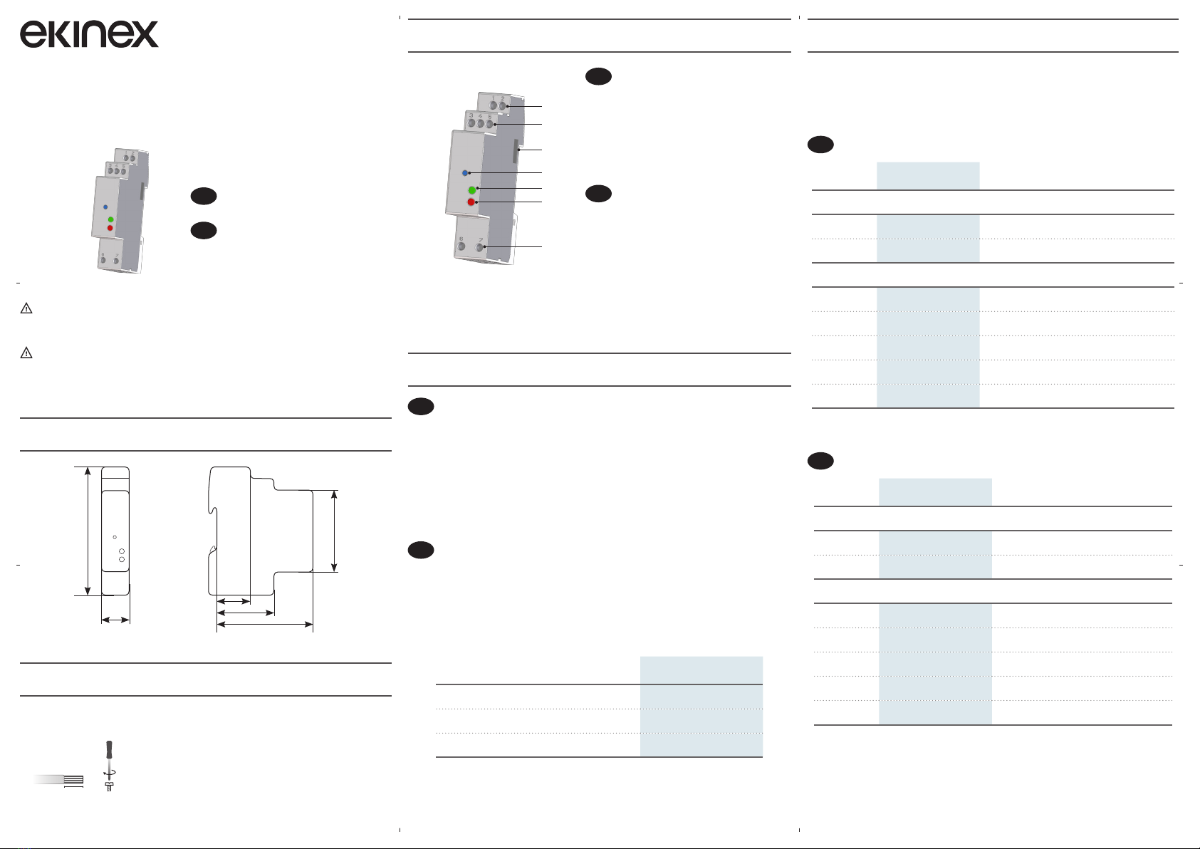
COLLEGAMENTI
CONNECTIONS
230 VAC
PONTICELLO PER ABILITARE RT
JUMPER FOR RT ENABLING
+
-
COM
I
- ITALIANO
Tra il PC e la rete RS485 è richiesto un convertitore seriale per adattare la porta RS232/USB alla
rete. Se i moduli da collegare sono più di 32, occorre inserire un ripetitore di segnale. Ogni ripetitore
può gestire fino a 32 moduli.
Il tipo di collegamento mostrato nella figura utilizza un terzo conduttore collegato al morsetto,
per assicurare lo stesso livello di riferimento a tutti i dispositivi di rete. In presenza di forti
disturbi elettromagnetici, che possono compromettere la comunicazione, è consigliabile l’utilizzo
di un apposito cavo schermato con i due conduttori di segnale “twistati”. All’interno del modulo
è integrata una resistenza di terminazione (RT) che può essere abilitata ponticellando i relativi
morsetti. Montare una resistenza di terminazione sul PC ed abilitarla sull’ultimo modulo connesso
sulla linea. L’impiego di queste resistenze riduce il segnale riflesso lungo la linea.
La massima lunghezza raccomandata per un collegamento è di circa 1200 m a 9600 bps. Per
lunghezze superiori è consigliabile utilizzare baudrate più bassi, cavi con bassa attenuazione o
ripetitori di segnale.
Dopo aver effettuato i collegamenti sulla rete RS485, abbinare ogni modulo RS485 ad un
singolo contatore: avvicinarli e allinearli perfettamente in modo che le rispettive porte ottiche si
fronteggino.
I parametri RS485 possono essere modificati direttamente sul contatore abbinato oppure inviando
gli appositi comandi di protocollo MODBUS al modulo.
EN
- ENGLISH
A serial converter is required between PC and the RS485 network to adapt RS232/USB port to
network. If there are more than 32 modules to be connected, insert a signal repeater. Each repeater
can manage up to 32 modules. For the connection among the different modules, use a cable
with a twisted pair and a third wire. The type of connection shown in the picture uses the third
conductor to ensure that all the devices on the network have the same reference level and improve
the reliability of communication. When there are strong electromagnetic disturbances, which may
affect communication, a shielded cable should be used. The module is integrated with a termination
resistor (RT) which can be enabled by jumpering the relevant terminals. The termination resistance
must be installed on the PC and enabled on the last module connected along the line. Thanks to
these resistances, the reflected signal along the line is reduced.
The maximum recommended distance for a connection is 1200 m at 9600 bps. For longer distances,
lower baud rates or low-attenuation cables or signal repeaters are needed.
After making RS485 connections, combine each RS485 module with a single counter: place them
side by side, perfectly lined up, with module optical port facing the counter optical port.
RS485 parameters can be changed directly on the combined counter or by sending the proper
MODBUS protocol commands to the module.
CONVERTITORE
CONVERTER
RS232/USB
RIPETITORE
REPEATER
max 32 moduli
max 32 modules
CONVERTITORE
CONVERTER
RS232/USB
COM
-
+
COM
- +
COM
- +
RT
ABILITARE RT SULL’ULTIMO MODULO
CONNESSO SULLA LINEA
ENABLE RT ON THE LAST MODULE
CONNECTED TO THE LINE