Ekinex EK-BH1-TP-485 User manual

Pag. 1
Gateway Modbus master RTU RS485 –
KNX TP
Code: EK-BH1-TP-485
Data sheet STEKBH1TP485_EN
V1.3 – 01 2019
KNX device with gateway function (protocol conversion)
between a serial RS485 Modbus RTU network (Master
function) and a KNX TP network over a twisted pair
communicaton cable. Ideal application in integration of
Modbus devices over a RS485 serial network in a KNX-
based automation system for homes and buildings.
Description
The Modbus master RTU RS485 ekinex® EK-BH1-TP-
485 gateway is a KNX modular unit for panel mounting.
It allows you to exchange informations with one or more
slave devices over a RS485 differential serial network
through Modbus RTU (Remote Terminal Unit) protocol.
The ekinex gateway acts as Modbus Master. The
informations exchanged over the Modbus network are
updated over the KNX network by means of a twisted
pair (TP) communication cable.
The device manages a two-way data stream: the
Modbus registers can be cyclically read and their value
sent as a communication object over the KNX TP
network through a multicast communication to
configured group addresses. The data update over the
KNX network can be done cyclically and/or on event of
change of the data acquired by the Modbus network.
Likewise, the ekinex gateway can make requests to
cyclically readings KNX communication objects or
acquire their values during data exchange over the bus.
Cyclically or on event of change of the communication
objects, data are written on the Modbus registers of one
or more configured devices.
The ekinex gateway supports the entire Modbus RTU
master protocol with the possibility of reading and writing
single and multiple 1-bit registers (Coil and Status) as
well as 16-bit registers (Holding and Input). It is also
possible to read and write multiple registers containing
32-bit floating point values (IEEE 754 format).
As for KNX communication, 1-bit, 1-byte, 2-byte and 4-
byte communication objects can be acquired: internal
conversion functions allow you to convert the
informations from and to 16-bit floating point values (DPT
9.xxx) starting from integer Modbus registers.
Configuration is performed through a PC application
software which communicates through the integrated
Ethernet port. The application software
CGEKBH1TP485 is available for download at
www.ekinex.com.
Main features
Modbus side
•RS485 serial communication port, electrically
isolated from power supply, 120 termination
resistance insertable by a 1-way microswitch
•Modbus master RTU (Remote Terminal Unit)
communication
•Selectable baud rate from 1200 to 115200 baud
•Device addressing from 0 to 250
•Coil, Input, Holding Register e Input Register data
exchange
•Single and multiple register reading/writing
•1440-byte volatile support “Modbus image” memory
buffer
KNX side
•KNX TP (Twisted Pair) communication port set to
9600 baud, electrically isolated from power supply
•1440-byte volatile support “KNX image” memory
buffer
Ethernet port
•Ethernet communication port (IEEE 802.3), RJ45
connector, minimum cable category: 5E.
Technical data
•Power supply: 8…24 Vac or 12…35 Vdc. Power
Absorption at 24 Vdc: 3,5 VA.
•Installation on 35 mm DIN rail (according to EN
60529)
•Plastic case
•Protection degree IP20 (according to EN 60529)
•Safety class II
•Weight 145 g
•Modular device 4 UM (1 UM = 18 mm)
•Dimensions 72 x 90 x 60 mm (WxHxD)
Environmental conditions
• Operating temperature: - 40 ... + 85°C
• Stock temperature: - 25 ... + 55°C
• Transportation temperature: - 25 ... + 70°C
• Relative humidity: 93% non-condensing
Display and command elements
The device is equipped with a pushbutton and a KNX
programming LED, with a status LED and terminal blocks
for KNX and RS485 network connection. A port for RJ45
connector for device configuration via Ethernet as well
as two 1-way microswitches are also present.
REAEKBH1TP485

Pag. 2
1) KNX bus line terminal blocks
2) KNX programming pushbutton
3) KNX programming LED
4) Power supply terminal blocks
5) 1-way microswitch A
6) Ethernet port
7) Ethernet port LED
8) Device satus LED
9) Modbus communication LED
10) KNX communication LED
11) Device error LED
12) RS485 serial line terminal blocks (3 Com, 4 RT-, 5 RT+)
13) 1-way microswitch B
Command elements
•Pushbutton that switches between normal mode and
KNX physical address programming.
1-way microswitches
•A - OFF: normal mode active. ON: Boot mode active
•B - OFF: open. ON: RS485 line termination inserted
(120 termination resistance in parallel between
RT+ and RT-)
Display elements
The device can run according to two operating modes:
Normal mode (configuration loaded, Modbus and KNX
communication running) and Boot mode (no
configuration or configuration still loading).
•Green LED (8) – Device status. Normal mode: Slow
blinking (~1 Hz). Boot mode: ON= device on; OFF=
device off.
•Yellow LED (9) – Modbus communication. Normal
mode: blinks when a frame is received on the RS485
port. Boot mode: if fast blinking: no configuration, if
very slow blinking (~0,5 Hz): loading configuration.
•Yellow LED (10) – KNX communication. Normal
mode: blinks when a frame is received. Boot mode: if
fast blinking: no configuration, if very slow blinking
(~0,5 Hz): loading configuration.
•Yellow LED (11) – Device error. Normal mode: ON=
at least one Modbus request did not get a correct
answer; OFF= no error. Boot mode: if fast blinking:
no configuration, if very slow blinking (~0,5 Hz):
loading configuration.
•Green LED (7) – Ethernet port. Normal mode: ON=
Ethernet connector plugged; OFF= Ethernet
connector unplugged. Boot mode: ON= Ethernet
connector plugged; OFF= Ethernet connector
unplugged.
•Red LED (3) – KNX programming. Normal mode:
ON= physical address programming mode on; OFF=
physical address programming mode off. Boot mode:
if fast blinking: no configuration, if very slow blinking
(~0,5 Hz): loading configuration.
Installation
The device has IP20 protection degree and is therefore
suitable for dry indoor environments. The case is suitable
for mouting on a DIN rail (according to EN 60715) inside
eletrical distribution cabinets. The proper installation
involves the bus terminal blocks to be in the lower side.
For installation proceed as follows:
•with the aid of a tool bring the locking device in
completely lowered position (1);
•place the device on the upper edge of the DIN rail
(2);
•rotate the device towards the DIN rail (3);
•push the locking device up untili il stops (4).
1
2
3
4
To unmount the device, make sure to unplug the network
connection and the bus terminal from its housing. Use a
screwdriver to slide down the lock and remove the device
from the rail.
Note. It is recommended to install the device so to
always guarantee full frontal accessibility, in order to
properly display the status LEDs.
Power supply connection
The device supports a very wide range of supply
1
2
5
4
12
6
7
8
9
10
11
13
3
Failure
KNX
Modbus
Device state
EK-BH1-TP-485
Modbus Master RS485 RTU
/ KNX TP Converter 1 2
8...24 Vac +V 0V
POWER S.
12...35 Vdc
3 4 5 RS485ETHERNET
Dev.
Line
Area
ON
ON
RT-Com RT+
DCEKBH1TP485
Pag. 3
voltages, both DC and AC.
Vmin
Vmax
Vac
8
24
Vdc
12
35
Important! In case of DC power supply, DO NOT
reverse the terminal blocks polarity!
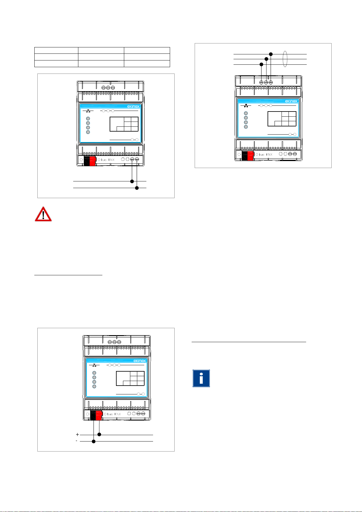
KNX connection
Connection to KNX bus is made via the supplied KNX
terminal block. The terminal block must be inserted into
the slot located on the lower front side of the device.
KNX terminal block features
•Conductors’ spring clamping
•4 conductors’ location for each polarity
•Suitable for KNX bus cables with single-wire
conductors (diameter between 0.6 and 0.8 mm)
•Recommended wire stripping: 5 mm
•Color code: red = bus conductor + (positive), black =
bus conductor – (negative)
RS485 Modbus connection
In order to terminate the RS485 network and balance the
line impedance, you must enter the terminating resistor
(120 Ω), by setting ON the 1-way microswitch B.
The maximum extension of the RS485 network is 1200
m.
Below are some recommended cable codes for wiring
the RS485 line:
•Belden code 8132. 2x 28AWG twisted pairs of
conductors + foil shielding + shielding mesh;
•Belden code 82842. 2x 24AWG twisted pairs of
conductors + foil shielding + shielding mesh;
•Tasker code C521. 1x 24AWG twisted wire pair + foil
shielding + shielding mesh;
•Tasker code C522. 2x 24AWG twisted pairs of
conductors + foil shielding + shielding mesh.
Configuration and commissioning
Configuration and commissioning of the ekinex®
gateway must be performed using the application
program CGEKBH1TP485, available for download at
www.ekinex.com.
System requirements for configuration software
•Desktop o laptop PC with Ethernet IEEE 802.3 port.
•32/64 bit operating system, Microsoft Windows® XP,
7, 8.0, 8.1 e 10.
Note. .NET Framework 4.0 system library installation is
required.
The ekinex® configuration software CG-EK-BH1-TP-485
allows you to perform the following operations:
•Selection of physical parameters of the RS485 serial
communication;
•Selection of physical address of the device over the
KNX TP network;
•Selection of Ethernet parameters (for configuration
download only);
•KNX network: communication objects definition and
relative group addresses to be acquired;
communication objects definition and relative group
addresses to be sent over the KNX network;
+
-
Alimentazione
Failure
KNX
Modbus
Device state
EK-BH1-TP-485
Modbus Master RS485 RTU
/ KNX TP Converter 1 2
8...24 Vac +V 0V
POWER S.
12...35 Vdc
3 4 5
RT-Com RS485ETHERNET
Dev.
Line
Area
RT+
+
-
Bus
KNX
Failure
KNX
Modbus
Device state
EK-BH1-TP-485
Modbus Master RS485 RTU
/ KNX TP Converter 1 2
8...24 Vac +V 0V
POWER S.
12...35 Vdc
3 4 5
RT-Com RS485ETHERNET
Dev.
Line
Area
RT+
RT+
RT-
Com
Failure
KNX
Modbus
Device state
EK-BH1-TP-485
Modbus Master RS485 RTU
/ KNX TP Converter 1 2
8...24 Vac +V 0V
POWER S.
12...35 Vdc
3 4 5
RT-Com RS485ETHERNET
Dev.
Line
Area
RT+
EL1EKBH1TP485
EL3EKBH1TP485
EL2EKBH1TP485
Pag. 4
•Modbus network: definition of the registers to be read
from the network devices and definition of the
registers to be written on the network devices;
•Firmware and/or configuration update.
Note. Configuration and commissioning of the ekinex®
gateway require specialized skills about KNX networks
and knowledge of the specific ETS automation project.
In order to acquire such skills, it is essential to attend
trainings and workshops organized at KNX-certified
training centers. For further information: www.knx.it.
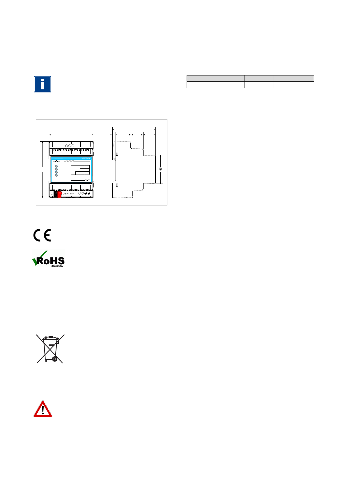
Dimensions [mm]
Certifications
The product complies with the Low Voltage
Directive (2006/95 / EC) and Electromagnetic
Compatibility Directive (2004/108 / EC)
The product is compliant with 2002/95 /
EC Directive about usage restriction of
certain hazardous substances in electrical and electronic
equipment (commonly referred to as the Restriction of
Hazardous Substances or RoHS).
Maintenance
The device is maintenance free. To clean it, use a dry
cloth. Using solvents or other aggressive substances is
strictly forbidden.
Disposal
The product described in this data
sheet, at the end of its useful life, is
classified as waste from electronic
equipment, according to the European
Directive 2002/96 / EC (WEEE),
implemented in Italy by Legislative
Decree no. 151 of 25 July 2005, and can not be disposed
as solid municipal waste.
Importante! Improper disposal of the product may cause
serious damage to the environment and human health.
For proper disposal refer to collection and treatment
informations provided by local authorities.
Document
This data sheet refers to the release A1.0 of the ekinex®
device code EK-BH1-TP-485 and is available for
download on the site www.ekinex.com PDF (Portable
Data Format).
Filename
Release
Update
STEKBH1TP485_EN.pdf
A1.0
11 / 2015
Warning
•Installation, electrical connection, configuration and
commissioning of the device can only be carried out
by qualified personnel.
•Opening the housing of the device causes the
immediate end of the warranty period.
•ekinex® KNX defective devices must be returned to
the manufacturer at the following address: EKINEX
S.p.A. Via Novara 37, I-28010 Vaprio d’Agogna (NO)
Italy.
Other information
•This application manual is aimed at installers, system
integrators and planners
•For further information on the product, please contact
the ekinex® technical support at the e-mail address:
www.ekinex.com
•KNX® and ETS® are registered trademarks of KNX
Association cvba, Brussels
© EKINEX S.p.A. The company reserves the right to make changes to
this documentation without notice.
72 525 20 20
70
46
90
Failure
KNX
Modbus
Device state
EK-BH1-TP-485
Modbus Master RS485 RTU
/ KNX TP Converter 1 2
8...24 Vac +V 0V
POWER S.
12...35 Vdc
3 4 5 RS485ETHERNET
Dev.
Line
Area
RT-Com RT+
DQEKBH1TP485
This manual suits for next models
1
Other Ekinex Gateway manuals


Popular Gateway manuals by other brands

LST
LST M500RFE-AS Specification sheet

Kinnex
Kinnex Media Gateway quick start guide

2N Telekomunikace
2N Telekomunikace 2N StarGate user manual

Mitsubishi Heavy Industries
Mitsubishi Heavy Industries Superlink SC-WBGW256 Original instructions

ZyXEL Communications
ZyXEL Communications ZYWALL2 ET 2WE user guide

Telsey
Telsey CPVA 500 - SIP Technical manual


